Cree CPW series Wideband MMIC amplifiers

Features and Applications of CPW series Wideband MMIC amplifiers

The purpose of this article is to briefly illustrate what is possible with Wideband MMIC amplifiers and the features and applications of these amplifiers manufactured by Cree under the CPW series.

Applications

  • Test & measurement
  • Wireless infrastructure
Associated Products

Part NumberDescriptionStockRFQ
CPW2-1200-S005BDIODE SCHOTTKY 1200V 5A0RFQ
CPW2-1200-S010BDIODE SCHOTTKY 1200V 10A0RFQ
CPW2-1200-S010BPDIODE SCHOTTKY 1200V 10A0RFQ
CPW2-0600-S010BRectifier Diode Schottky 600V 30A 2-Pin Chip0RFQ
Technical Documents

Microwave MMIC Amplifier, s21 Gain, s12 Isolation, s11 VSWR of ports

MMIC Amplifiers


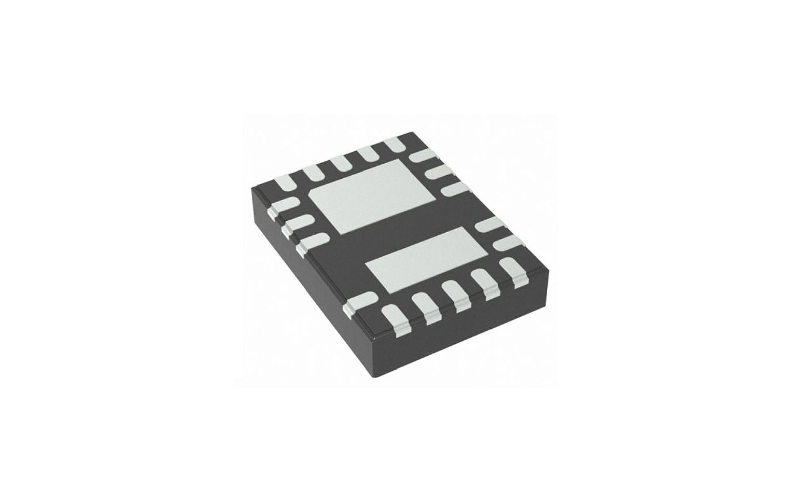
CPW series Wideband MMIC amplifiers are a type of monolithic microwave integrated circuit (MMIC) amplifiers that use coplanar waveguide (CPW) layout technologies for sub-miniature packaging and impedance matchingThey are designed for flip-chip packaged power amplifiers that operate at 14 GHzThey have applications in 5G, electronic warfare, radars, test and measurement and satellite, and military communications.

Features

The main features of CPW series Wideband MMIC amplifiers may be summarized as follows:

1. GaN on SiC technology for high efficiency and performance

2. Operate at 14 GHz frequency band with an instantaneous bandwidth of 2 to 18 GHz

3. Flip-chip packaged power amplifier design for sub-miniature packaging and impedance matching

4. Coplanar waveguide (CPW) layout technology for low loss and easy integration

5.High output power gain and stability across the band

Applications

  • 5G cellular transmitter amplifiers

  • Mobile communication systems and satellite systems

  • Phased array radar systems

  • Electronic warfare systems

  • Test and measurement systems

CPW series Wideband MMIC amplifiers offer faster data transmission speed, better latency values, and higher bandwidth capacity than 4G and LTE network technologiesThey have a better range and coverage than mmWave 5G networks, as they can travel further and penetrate physical objects betterThey have cost-efficient infrastructure requirements, as they can use existing network towers with minor modifications.


Related Series

Frequently Asked Questions

What is the chip area and power consumption of CPW series Wideband MMIC amplifiers from Cree?

The chip area of a CPW MMIC power amplifier for flip-chip packaged power amplifiers at 14 GHz is 1.5 mm x 1.5 mm. The power consumption of a CPW MMIC power amplifier for flip-chip packaged power amplifiers at 14 GHz is 0.9 W. The chip area of a wideband high-efficiency GaN MMIC power amplifier for Sub-6-GHz applications is 14.35 mm^2 including testing pads. The power consumption of a wideband high-efficiency GaN MMIC power amplifier for Sub-6-GHz applications is 3.8 W at 2 GHz and 4.5 W at 6 GHz. The chip area of a CPW power amplifier MMIC using CPW structure technology at 12 GHz is 1.8 mm x 1.8 mm. The power consumption of a CPW power amplifier MMIC using CPW structure technology at 12 GHz is 0.7 W.

How do CPW series Wideband MMIC amplifiers from Cree achieve high output power gain and stability across the band?

A harmonic load-pull and radial stub matching technique to optimize the output power and efficiency over a wide frequency range. A gain equalization technique in the inter-stage matching circuit to obtain a flat gain while maintaining the wideband characteristic. A low-loss output matching network to ensure high efficiency. A fully matched 50 Ω input and output impedances without any external circuit to improve the power performance.

What are the benefits of using a gain equalization technique in the inter-stage matching circuit of CPW series Wideband MMIC amplifiers from Cree?

It helps to achieve a flat gain over a wide frequency range, which is desirable for wideband applications. It reduces the gain ripple and variation caused by the mismatch between the driver stage and the power stage. It improves the linearity and output power of the amplifier by optimizing the load impedance for each stage.