Product
 Brand
Brand Articles
 Tools
Tools
Introduction to Synchronous Counter and Asynchronous Counter

Comparison between Ripple and Synchronous counters
Digital counters are fundamental components in electronic systems, primarily constructed using flip-flops. These counters can be classified into two main categories based on their flip-flop triggering mechanism: synchronous and asynchronous counters. In a synchronous counter, all flip-flops flip at the same time when the count pulse is input; while in an asynchronous counter, the flip-flops at all levels are not flipped simultaneously. If classified according to the increase or decrease of the number in the counter during the counting process, it can be divided into an addition counter, a subtraction counter and a reversible counter (also known as an up/down counter). The up-counter counts up with the continuous input of counting pulses; the down counter counts down with the continuous input of counting pulses; the up and down counters are called reversible counters.
Catalog
| |
| |
3.Asynchronous decimal counter constructed with JK flip-flop | |
Ⅰ Synchronous counter
Synchronous counter refers to the accumulated value of the measured value, which is characterized by greatly improving the working frequency of the counter, and corresponds to the asynchronous counter. For the synchronous counter, since the clock pulse acts on each flip-flop at the same time, the problem of the step-by-step delay of the flip-flop encountered by the asynchronous flip-flop is overcome, so the working frequency of the counter is greatly improved. However, if the number of synchronous counter stages increases, the load on the count pulse will increase.
In synchronous counters, all flip-flops receive the clock pulse simultaneously, enabling concurrent state transitions (Mano & Ciletti, 2018). This synchronized operation offers several advantages:
Key Features:
Simultaneous state updates across all flip-flops
Higher operating frequencies compared to asynchronous designs
State transitions dependent on both current and subsequent flip-flop states
Multiple carry methods: serial and parallel, with parallel offering superior speed
1.Circuit configuration
Asynchronous counters and synchronous counters are basically the same in principle, function, classification, etc. except for different circuit structures. Figure 1 is a three-bit binary addition counter with M=2 composed of three JK flip-flops. The count pulse N is added to the CP end of each flip-flop clock at the same time, and the flip-flop state update is performed simultaneously.

Figure 1. Synchronous addition counter circuit
Figure 2 is a synchronous three-bit binary subtraction counter. The difference from Figure 1 is that each flip-flop leads from the Q terminal to the JK terminal of the next bit, and the non-Q enters the AND gate as the high-order JK terminal input.

Figure 2. Synchronous subtraction counter circuit
The state diagram of the subtraction counter is shown in Figure 3.
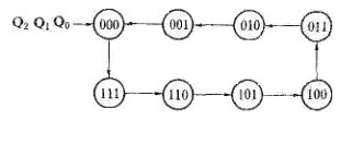
Figure 3. State diagram of subtraction counter
2.Features
①The state of each flip-flop is updated simultaneously; ②The state of the flip-flop is determined by the current state of the previous stage and the next state of the subsequent stage; ③Compared with the asynchronous counter circuit structure, it needs the cooperation of the gate circuit, but the counting speed is faster than asynchronous counters; ④There are two types of methods of circuit carry: serial and parallel. The parallel carry method can further increase the counting speed.
Ⅱ Asynchronous counter
Asynchronous counters, also known as ripple counters, operate with cascaded flip-flops where the output of one stage drives the clock input of the subsequent stage (Floyd, 2019). This design creates a propagation delay as changes "ripple" through the counter stages.
Performance Considerations:
Clock Distribution: Synchronous counters require more complex clock distribution but offer better timing precision
Speed: Synchronous designs achieve higher operating frequencies due to eliminated ripple delays
Power Consumption: Asynchronous counters typically consume less power due to simpler clock distribution
Circuit Complexity: Synchronous designs generally require additional logic gates but provide superior performance
Its main feature is that the clock pulse terminals CP of the internal flip-flops are not all connected together. Therefore, the flipping time of each flip-flop may come first, and its output may produce interference glitches, but its circuit structure is simple.
1.Asynchronous binary addition counter
The asynchronous binary counter is used to carry out bit by bit from low to high when counting up. Therefore, the flip-flops are not flipped synchronously. According to the binary addition counting rule, if the i-th bit is 1, it becomes 0 when 1 is added, and a carry signal is sent to the high bit to flip the high bit. If a T' flip-flop is used to form a counter circuit, only the Q terminal of the low flip-flop needs to be connected to the clock input terminal of the high flip-flop to realize the carry. When the low bit changes from 1 to 0, the falling edge of the Q terminal can be used as the high clock signal (if the T' flip-flop triggered by the falling edge is used), or the rising edge of the Q terminal can be used as the high clock signal (if the rising edge is used T' trigger).
2.Asynchronous binary subtraction counter
According to the binary subtraction counting rule, if the low flip-flop is already 0, it should be flipped to 1 after another subtraction counting pulse is input, and a borrow signal is sent to the high bit to flip the high bit. If a T' flip-flop is used to form a counter circuit, then only the Q terminal of the low flip-flop needs to be connected to the clock input terminal of the high flip-flop to achieve carry. When the low bit changes from 0 to 1, the falling edge of the Q terminal can be used as the high clock signal (if the T' flip-flop triggered by the falling edge is used), or the rising edge of the Q terminal can be used as the high clock signal (if the rising edge is used T' trigger).
3.Asynchronous decimal counter constructed with JK flip-flop
The asynchronous decimal addition counter is obtained on the basis of the 4-bit asynchronous binary addition counter, as shown in Figure. The main problem to be solved during the modification is how to make the 4-bit binary counter skip the 6 states of 1010-1111 during the counting process. Assuming that the selected flip-flops are all TTL when circuits J and K are floating, it is equivalent to a logic 1 level.
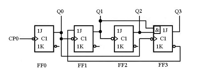
Figure 4. Asynchronous decimal addition counter
If the counter starts counting from Q3Q2Q1Q0-0000, it can be seen from Figure that the signal input terminals J and K of the flip-flops FF0, FF1, and FF2 are always 1, which is a T' flip-flop. It works before the 8th count pulse is input. The process is the same as the asynchronous binary addition counter. During this period, although the pulse output by Q0 is also sent to the flip-flop FF3, since J3=Q2Q1=0 and K3=1 each time the falling edge of Q arrives, the flip-flop FF3 keeps the 0 states.
When the eighth count pulse is input (the status of the counter is Q3Q2Q1Q0-0111 at this time), since J3=K3=1, Q3 changes from 0 to 1 after the falling edge of Q0 arrives. At the same time, J1 becomes 0 with Q3. After the 9th count pulse is input, the circuit state becomes Q3Q2Q1Q0-1001. After the 10th count pulse is input, the flip-flop FF0 turns over to 0, and the falling edge of Q0 sets the flip-flop FF3 to 0. So the circuit returns from 1001 to 0000, skipping the 6 states of 1010-1111, and becomes a decimal counter.
4.Pinout diagram and logic function
The figure below shows the pin arrangement diagram and logic function diagram of the asynchronous decimal counter 74290. It consists of three JK type triggers, one RS-type trigger, and several additional doors. R01 and R02 are asynchronous clear terminals: S91 and S92 are asynchronous set 9 terminals. The whole circuit can be seen as composed of two independent counters. Counter I is a one-bit binary counter composed of a flip-flop, the clock pulse terminal is CP0, and the status output terminal is Q0; Counter II is a five-ary asynchronous counter composed of three flip-flops, and its clock pulse terminal is CP1, and the status output terminal is Q1Q2Q3.
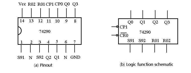
Figure 5. asynchronous decimal counter 74290
References:
Floyd, T. L. (2019). Digital Fundamentals (12th ed.). Pearson Education.
https://www.pearson.com/en-us/subject-catalog/p/digital-fundamentals/P200000003220
Mano, M. M., & Ciletti, M. D. (2018). Digital Design: With an Introduction to the Verilog HDL, VHDL, and SystemVerilog (6th ed.). Pearson.
https://www.pearson.com/en-us/subject-catalog/p/digital-design-with-an-introduction-to-the-verilog-hdl-vhdl-and-systemverilog/P200000003258
Tocci, R. J., Widmer, N. S., & Moss, G. L. (2017). Digital Systems: Principles and Applications (12th ed.). Pearson.
https://www.pearson.com/en-us/subject-catalog/p/digital-systems-principles-and-applications/P200000003259
Wakerly, J. F. (2017). Digital Design: Principles and Practices (5th ed.). Pearson.
https://www.pearson.com/en-us/subject-catalog/p/digital-design-principles-and-practices/P200000003261
 UTMEL
UTMEL
We are the professional distributor of electronic components, providing a large variety of products to save you a lot of time, effort, and cost with our efficient self-customized service. careful order preparation fast delivery service
1.Why asynchronous counter is called the ripple counter?
Asynchronous counters are sometimes called ripple counters because the data appears to “ripple” from the output of one flip-flop to the input of the next. They can be implemented using “divide-by-n” counter circuits.
2.What is the synchronous counter?
In synchronous counters, the counting sequence is controlled by means of a clock pulse and all the changes of the outputs of all flip-flops occur in synchronism. When the input pulse falls to the '0' level, the new values of the count are transmitted synchronously to the outputs of the flip-flops.
3.Which is a better synchronous or asynchronous counter?
Synchronous counters are easier to design than asynchronous counters. are all clocked together at the same time with the same clock signal. Due to this common clock pulse, all output states switch or change simultaneously. The overall faster operation may be achieved compared to Asynchronous counters.
4.What is the difference between asynchronous and synchronous counters?
Synchronous counters have an internal clock, whereas asynchronous counters do not. As a result, all the flip-flops in a synchronous counter are driven simultaneously by a single, common clock pulse. This is the essential difference between synchronous and asynchronous counters.
5.Is synchronous faster than asynchronous?
In synchronous transmission data is transmitted in the form of chunks, while in asynchronous transmission data is transmitted one byte at a time. The data transfer rate of synchronous transmission is faster since it transmits in chunks of data, compared to asynchronous transmission which transmits one byte at a time.
6.What is the advantage of a synchronous counter?
The one advantage of synchronous counter over asynchronous counter is, it can operate on higher frequency than asynchronous counter as it does not have cumulative delay because of same clock is given to each flip flop.
7.What are the types of the counter?
7.What are the types of the counter? Types of Electronic Counters Synchronous counter. Asynchronous Counter or Ripple Counter. Up/Down Counter. Decade Counter. Ring counter. Cascaded counter. Johnson counter. Modulus counter.
 Introduction to Synchronous Counter and Asynchronous CounterUTMEL31 March 202518497
The counter is mainly composed of flip-flops. According to the flip order of flip-flops, the counter can be divided into synchronous and asynchronous.
Read More What is Digital Counter?UTMEL01 September 202012977
Counting is one of the simplest basic operations. In digital logic and computing, the counter is the logic circuit that realizes this kind of operation. In the digital system, the counter mainly counts the number of pulses to realize the functions of measurement, counting, and control.
Read More
Subscribe to Utmel !
![ACDC2101]() ACDC2101
ACDC2101NVE Corporation
![ACPL75188]() ACPL75188
ACPL75188NVE Corporation
![ACDC2405]() ACDC2405
ACDC2405NVE Corporation
![ACPL75186]() ACPL75186
ACPL75186NVE Corporation
![ACDC2106]() ACDC2106
ACDC2106NVE Corporation
![0M-ALVA1011X1P]() 0M-ALVA1011X1P
0M-ALVA1011X1PNVE Corporation
![0M-ALRD0399X1P]() 0M-ALRD0399X1P
0M-ALRD0399X1PNVE Corporation
![ACAC76119]() ACAC76119
ACAC76119NVE Corporation
![0M-ALRE0773X1P]() 0M-ALRE0773X1P
0M-ALRE0773X1PNVE Corporation
![ACDC2018]() ACDC2018
ACDC2018NVE Corporation