Product
 Brand
Brand Articles
 Tools
Tools
What is Digital Counter?

Introduction to Counters
Catalog
Ⅰ Introduction
Counting is one of the simplest basic operations. In digital logic and computing, the counter is the logic circuit that realizes this kind of operation. In the digital system, the counter mainly counts the number of pulses to realize the functions of measurement, counting, and control. It also has the function of frequency division. The digital counter is composed of the basic counting unit and some control gates, and the counting unit is composed of a series of various triggers with the function of storing information. These triggers include RS triggers, T triggers, D triggers, and JK triggers. Counters are widely used in digital systems. For example, in the controller of an electronic computer, the instruction address is counted to fetch the next instruction in sequence. The number of additions and subtractions is recorded when the arithmetic unit performs multiplication and division operations. The counter can be used to display the working status of the product. Generally speaking, it is mainly used to indicate how many copies of the folding and collating work the product has completed. Its main indicator lies in the number of digits of the counter, the common ones are 3 and 4 digits. Obviously, a 3-digit counter can display up to 999, and a 4-digit counter can display up to 9999.
Ⅱ Classification
1. According to whether the flip-flops in the counter are flipped at the same time, the counter can be divided into two types: synchronous counter and asynchronous counter.
2. According to the increase and decrease of numbers in the counting process, the counters can be divided into addition counters, subtraction counters, and reversible counters. The ones that keep increasing with the clock signal are the addition counters, and the ones that keep decreasing are the subtraction counters. The ones that can increase or decrease are called Reversible counter.
The most commonly used is the first category because this category allows people to know at a glance what trigger mode this counter is so that the designer can design the circuit. Also, counters are often divided into binary counters, decimal counters, etc. according to their counting system.
Ⅲ Application
The digital counter supports recording calls, text messages, data, etc., and supports users to independently select the clearing date and add reminder values according to categories. For example, users can choose any day of the month or the first and last day as the recording cycle clearing day, and a reminder node for the duration of the call, the number of SMS messages, and the number of data traffic is added at the same time.
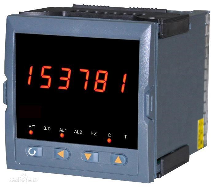
Figure 1. Digital display counter
The application of the counter is extremely wide. Not only can it be used for counting, but also frequency division, timing, and to form various detection circuits and control circuits.
For ease of use, some monolithic integrated counters are also added with asynchronous zeroing, preset number, hold, and other functions, and set the corresponding control terminal.
The digital counter has the characteristics of being used in the industry: 1. It has a 6-digit LED digital display; 2. It has two counting inputs for A and B at the same time; 3. The counting frequency can reach 20KHz; 4. It also has an LED warning light indicator; 5. Support RS485, RS232 serial interface at the same time, the output, power supply, and communication adopt photoelectric isolation and do not interfere with each other.
Ⅳ Synchronous counter
Synchronous counter refers to the cumulative value of the measured value, which is characterized by greatly increasing the working frequency of the counter. The corresponding is an asynchronous counter. For the synchronous counter, since the clock pulse acts on each flip-flop at the same time, the problem of the step-by-step delay of the flip-flop encountered by the asynchronous flip-flop is overcome, so the working frequency of the counter is greatly improved. However, if the number of synchronous counter stages increases, the load of counting pulses will increase.

Figure 2. Synchronization counter
1. Circuit configuration

Figure 3. Synchronous addition counter circuit
Compared with asynchronous counters, synchronous counters are basically the same in principle, function, classification, etc. except for different circuit structures. Figure 3 is a three-bit binary addition counter with M=2 composed of three JK flip-flops. The count pulse N is added to the CP end of each flip-flop clock at the same time, and the flip-flop state update is performed simultaneously.

Figure 4. Synchronous subtraction counter circuit
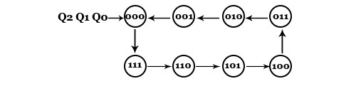
Figure 5. State diagram of subtraction counter
Figure 4 is a synchronous three-bit binary subtraction counter. The difference from Figure 3 is that each flip-flop leads from the Q terminal to the JK terminal of the next bit, and the non-Q enters the AND gate as the high-order JK terminal input.
2. Classification
①Divided by modulus (M): there are modulo 2 (M=2) counters and modulo 2 (M≠2) counters, which are often called binary counters and non-binary counters accordingly. ②According to the status update status of the trigger, there are asynchronous counters and synchronous counters. ③According to the count output status, there are up and down counters, including addition counter, subtraction counter, and reversible counter (that is, in the same circuit, the addition or subtraction control signal can control the addition or subtraction counting).
3. Features
①The state of each flip-flop is updated simultaneously; ②The state of the flip-flop is determined by the current state of the previous stage and the next stage of the subsequent stage; ③Compared with the asynchronous counter circuit structure, it needs the cooperation of the gate circuit, but the counting speed is faster than asynchronous; ④There are two types of methods of circuit carry: serial and parallel. The parallel carry method can further increase the counting speed.
Ⅴ Asynchronous counter
The asynchronous counter is an asynchronous sequential circuit. Its main feature is that the clock pulse terminals CP of the internal flip-flops are not all connected. Therefore, the flipping time of each flip-flop is not uniform, and its output may produce interference glitches, but its circuit structure is simple.
1. Asynchronous Binary Adding Counter
When the asynchronous binary counter is doing addition counting, it is carried out in a way T from low to high bit by bit. Therefore, the flip-flops are not flipped synchronously. According to the binary addition counting rule, if the i-th bit is 1, it becomes 0 when 1 is added, and a carry signal is sent to the high bit to flip the high bit. If a T'flip-flop is used to form a counter circuit, only the Q (or Q) terminal of the low flip-flop needs to be connected to the clock input terminal of the high flip-flop to achieve carry. When the low bit changes from 1 to 0, the falling edge of the Q terminal can be used as the high clock signal (if the T'flip-flop triggered by the falling edge is used), or the rising edge of the Q terminal can be used as the high clock signal (if the rising edge is used T' Trigger).
2. Asynchronous binary subtraction counter
According to the binary subtraction counting rule, if the low flip-flop is already 0, it should be flipped to 1 after another subtraction counting pulse is input, and a borrow signal is sent to the high bit to flip the high bit. If a T' flip-flop is used to form a counter circuit, only the Q terminal of the low-level flip-flop needs to be connected to the clock input terminal of the high-level flip-flop to achieve carry. When the low bit changes from 0 to 1, the falling edge of the Q terminal can be used as the high clock signal (if the T' flip-flop triggered by the falling edge is used), or the rising edge of the Q terminal can be used as the high clock signal (if the rising edge is used T' trigger).
3. Asynchronous decimal counter constructed with JK flip-flop
The asynchronous decimal addition counter is obtained based on the 4-bit asynchronous binary addition counter, as shown in Figure 5. The main problem to be solved during the modification is how to make the 4-bit binary counter skip the 6 states of 1010-1111 during the counting process. Assuming that the selected flip-flops are all TTL when circuits J and K are floating, it is equivalent to a logic 1 level.

Figure 6. Asynchronous decimal addition counter
If the counter starts counting from Q3Q2Q1Q0-0000, it can be seen from Figure 6 that the signal input terminals J and K of the flip-flops FF0, FF1, and FF2 are always 1, which is a T' flip-flop. It will work before the 8th count pulse is input. The process is the same as the asynchronous binary addition counter. During this period, although the pulse output by Q0 is also sent to the flip-flop FF3. Since J3=Q2Q1=0 and K3=1, each time the falling edge of Q arrives, the flip-flop FF3 keeps the 0 states.
When the 8th count pulse is input (the status of the counter is Q3Q2Q1Q0-0111 at this time). Since J3=K3=1, Q3 changes from 0 to 1 after the falling edge of Q0 arrives. At the same time, J1 becomes 0 with Q3. After the 9th count pulse is input, the circuit state becomes Q3Q2Q1Q0-1001. After the 10th count pulse is input, the flip-flop FF0 turns over to 0. and the falling edge of Q0 sets the flip-flop FF3 to 0, so the circuit returns from 1001 to 0000, skipping the 6 states of 1010-1111, and becomes a decimal counter.
4. Pinout diagram and logic function
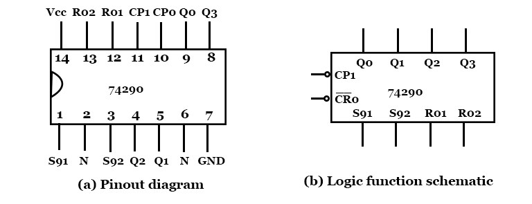
Figure 7. Asynchronous counter pin layout diagram and logic function diagram
Figure 7 shows the pin arrangement diagram and logic function diagram of the asynchronous two-one-five-one decimal counter 74290. It consists of three JK-type flip-flops, one RS-type flip-flop, and several additional gates. R01 and R02 are asynchronous clear terminals: S91 and S92 are asynchronous set 9 terminals. The whole circuit can be seen as composed of two independent counters. Counter I is a one-bit binary counter composed of a flip-flop, its clock pulse terminal is CP0, and the status output terminal is Q0; counter II is a Hexadecimal asynchronous counter composed of three flip-flops, and its clock pulse terminal is CP1. The status output terminal is Q1Q2Q3.
 UTMEL
UTMEL
We are the professional distributor of electronic components, providing a large variety of products to save you a lot of time, effort, and cost with our efficient self-customized service. careful order preparation fast delivery service
1.How do digital counters work?
The counter is a digital device and the output of the counter includes a predefined state based on the clock pulse applications. The output of the counter can be used to count the number of pulses. Generally, counters consist of a flip-flop arrangement which can be synchronous counter or asynchronous counter.
2.What is a counter in digital electronics?
In digital logic and computing, a counter is a device that stores (and sometimes displays) the number of times a particular event or process has occurred, often in relationship to a clock. The most common type is a sequential digital logic circuit with an input line called the clock and multiple output lines.
3.What is counter and its types?
The counter is a sequential circuit. A digital circuit that is used for a counting pulse is a known counter. The counter is the widest application of flip-flops. Counters are of two types. Asynchronous or ripple counters.
4.What does a counter do?
Counters are used in digital electronics for counting purposes, they can count specific events happening in the circuit. For example, in the UP counter a counter increases the count for every rising edge of the clock.
5.Which flip flop is used in counters?
Since there are only two states, a T-type flip-flop is ideal for use in frequency division and binary counter design. Binary ripple counters can be built using “Toggle” or “T-type flip-flops” by connecting the output of one to the clock input of the next.
 Introduction to Synchronous Counter and Asynchronous CounterUTMEL31 March 202518361
The counter is mainly composed of flip-flops. According to the flip order of flip-flops, the counter can be divided into synchronous and asynchronous.
Read More What is Digital Counter?UTMEL01 September 202012857
Counting is one of the simplest basic operations. In digital logic and computing, the counter is the logic circuit that realizes this kind of operation. In the digital system, the counter mainly counts the number of pulses to realize the functions of measurement, counting, and control.
Read More
Subscribe to Utmel !
![9G1224M401]() 9G1224M401
9G1224M401EAO
![FBA08A24H1A]() FBA08A24H1A
FBA08A24H1APanasonic
![CFM-4020V-050-165-11]() CFM-4020V-050-165-11
CFM-4020V-050-165-11CUI Inc
![CFM-6010V-140-285-20]() CFM-6010V-140-285-20
CFM-6010V-140-285-20CUI Inc
![CFM-5010V-155-310-20]() CFM-5010V-155-310-20
CFM-5010V-155-310-20CUI Inc
![CFM-9225V-227-320]() CFM-9225V-227-320
CFM-9225V-227-320CUI Inc
![A17820-03]() A17820-03
A17820-03Laird
![A17927-06]() A17927-06
A17927-06Laird
![A17819-03]() A17819-03
A17819-03Laird
![A17927-05]() A17927-05
A17927-05Laird