
 Product
 Brand
Brand Articles
 Tools
Tools
What's the Difference Between Operational Amplifier and Comparator?
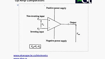
Operational Amplifiers - Comparators
What is the difference between op amps and comparators in terms of appearance or drawing symbols, and how can they be differentiated in practical applications? Today, I'll conduct a thorough examination of photographs and words, cement everyone's foundation, and allow engineers to advance to the next level.
First, let's look at their internal difference chart:

Figure. 1

Figure. 2
The output circuit distinguishes an op amp from a comparator, as can be seen in the internal diagram. The comparator employs only one transistor, with the collector linked to the output and the emitter connected to ground, whereas the op amp uses a twin transistor push-pull output.
From the positive power supply wire to the output terminal, the comparator requires an external pull-up resistor that is equal to the transistor's collector resistance.
Linear amplification circuits (negative feedback) and non-linear signal voltage comparisons can both benefit from operational amplifiers (open loop or positive feedback).
Voltage comparators are only suitable for comparing signal voltages, not for linear amplifier circuits (comparators have no frequency compensation).
The comparator is built as a high-speed switch, which has a higher slew rate and shorter latency than an op amp, and can be used for signal voltage comparison.
Ⅰ. Operational amplifier
I won't speak much about this circuit because it's a linear amplifier (the amplifier needs to be discussed separately in the future). This is a regular occurrence in motherboard circuit diagrams. It's commonly found in voltage regulator circuits. When paired with a transistor, a negative feedback circuit is similar to a three-terminal stabilizer. pressure, but more versatile to employ. As seen in the diagram below:

Figure. 3
In many circumstances, knowing which of the two signals is greater or when one signal exceeds a predefined voltage is required (used as a voltage comparison). It's simple to make this with an op amp and a basic circuit. The output is high when the V+ voltage is greater than the V- voltage. The output is low when the V+ voltage is smaller than the V- voltage. As shown in Figure. 4.

Figure. 4
Analyze the circuit: 2.5 volts is divided by the resistor to get 1 volts, which is then applied to the V- terminal. The bus voltage is sent into V+ when it generates 1.2v regularly. The V+ voltage is higher than the V- voltage at this point, and the CPU power management receives a high signal. The chip's EN pin is used to enable the chip. The V+ value is lower than the V- voltage at this moment, and the output is low if the bus voltage is not output or is unusually less than 1v.
Ⅱ. Voltage comparator
The output transistor is turned on and the output is grounded low when the comparator's non-inverting terminal voltage (V+) is lower than the inverting terminal voltage (V-); the pull-up resistor's power output is high. As seen in the diagram below:

Figure. 5
When there is a VCC output, the comparator U8A is connected to the non-inverting terminal (V+) after being divided by the voltage dividing resistor, and its voltage is larger than 5VSB, thus it is connected to the inverting terminal (V-) after the voltage division. The internal transistor is turned off, and the power supply 12v is output via the pull-up resistor (at the same time, the voltage of the non-inverting terminal of the comparator U8B below is greater than the inverting terminal, and the internal transistor is also turned off), the N-channel field transistor Q37 is turned on, and the output VCC5V is turned on. The P-channel field transistor Q293 is also turned off at the same moment. When the inverting terminal voltage exceeds the non-inverting terminal voltage, the internal transistor is activated, the pull-up power supply 12V is reduced, the N-channel field transistor Q37 is switch ed off, and the P-channel field transistor Q293 is activated, producing 5VSB. This is the 5VDUAL generation circuit.
In practical applications, comparators all require pull-up power supplies, while operational amplifiers generally do not.
Ⅲ. The essential difference between operational amplifier and voltage comparator
(1) The closed-loop characteristics are the key distinction between amplifiers and comparators!
Because most amplifiers operate in a closed-loop mode, they must not be self-excited after closing the loop. And the vast majority of comparators operate in an open-loop mode in order to maximize speed. The amplifier can totally replace the comparator in the case of relatively low frequency (the output level must be addressed), and vice versa. In most circumstances, comparators cannot be utilized as amplifiers.
Because the comparator has been tuned for speed, the closed-loop stable range has been reduced. Because the op amp is tuned for closed-loop stability, the speed is lowered. As a result, comparators and amplifiers of the same price range should ideally be different. Responsibility. It can't be ruled out that a comparator can be utilized as an amplifier, just as an amplifier can be used as a comparator. However, the cost of making it closed-loop stable may outweigh the cost of adding an amplifier.
In other words, the negative feedback depth of the circuit determines whether an op amp is utilized as a comparator or an amplifier. As a result, a shallow closed-loop comparator that is not self-excited can work in the amplifier state. However, many tests must be carried out to verify that the product is stable in all operating modes! You must carefully analyze the cost/risk at this time.
The operational amplifier and comparator are the same thing. The comparator is essentially an open-loop application of the operational amplifier, but it is built for voltage threshold comparison. The required comparison threshold is accurate, and following the comparison, the output edge rises. Alternatively, the fall time should be short, the output should conform to TTL /CMOS level/or OC, etc., the intermediate link precision is not necessary, and the driving capability is also different. In general, when employing op amps as comparators, most of them are unable to produce full-scale output, or the edge time after comparison is too long, therefore it is preferable to use less op amps in the design.
Ⅳ. Difference between operational amplifier and comparator
Despite the fact that the comparator and op amp have the same symbols on the circuit diagram, the two devices are extremely distinct and cannot be used interchangeably. The following are the distinctions:
1. The comparator's flipping speed is quick, on the order of ns, whereas the op amp's flipping speed is on the order of us (except for special high-speed op amps).
2. Although the op amp can be connected to a negative feedback circuit, the comparator cannot. Although the comparator contains two input terminals, in-phase and in-phase, the circuit does not work reliably if negative feedback is added since there is no phase compensation circuit inside.The comparator is substantially faster than the op amp since it does not have an internal phase adjustment circuit.
3. The operational amplifier's output stage is typically a push-pull circuit with bipolar output. Because most comparators have an open-collector output stage, they require a pull-up resistor, have a unipolar output, and are simple to connect to digital circuits.
(3) The comparator output has an open collector (OC) structure, which necessitates the use of a pull-up resistor to enable external current output. The op amp's output stage is a push-pull design with symmetrical sourcing and sinking capabilities. Furthermore, there are few intermediate steps to speed up the comparator's reaction speed, and there is no internal frequency adjustment. For the needs of working in the linear domain, the op amp has a compensating circuit. As a result, comparators aren't appropriate for op amps.
 UTMEL
UTMEL
We are the professional distributor of electronic components, providing a large variety of products to save you a lot of time, effort, and cost with our efficient self-customized service. careful order preparation fast delivery service
1. How Comparator Works?
The working principle of the comparator is that the output state will change when the voltage between the two input terminals crosses zero. Since the input terminal is often superimposed with a small fluctuation voltage, the differential mode voltage generated by these fluctuations will cause the comparator output to occur. Continuously changing, to avoid output oscillation, newer comparators typically have a hysteresis voltage of a few mV.
2. How to distinguish an op amp and a voltage comparator in a circuit?
Very simple, see if there is a feedback line.
What they use is a device, but the peripheral circuits are different, and the working states of the circuits are different.
The op amp works in a deep negative feedback state, and a line is drawn from the output to the input. So there is a feedback resistor.
Comparator does not. Input signals directly from both inputs.
3. What is the difference between a voltage comparator and an op amp?
One is the difference in application input. One of the two input terminals of the voltage comparator is connected to the reference voltage and the other terminal is connected to the comparison voltage. The op amp can be single-ended input or balanced input. Second, the open-loop gain of the voltage comparator is large, and the op amp is relatively Small: due to the large open-loop gain of the voltage comparator, when the input voltage is higher or lower than the reference, its output is jumping (that is, the rising or falling edge is very steep), the output of the op amp changes linearly, and then the application There is a difference. In order to work stably and reliably, the op amp generally uses negative feedback, and the voltage comparator does not add negative feedback.
 Discovering New and Advanced Methodology for Determining the Dynamic Characterization of Wide Bandgap DevicesSaumitra Jagdale15 March 20242617
For a long era, silicon has stood out as the primary material for fabricating electronic devices due to its affordability, moderate efficiency, and performance capabilities. Despite its widespread use, silicon faces several limitations that render it unsuitable for applications involving high power and elevated temperatures. As technological advancements continue and the industry demands enhanced efficiency from devices, these limitations become increasingly vivid. In the quest for electronic devices that are more potent, efficient, and compact, wide bandgap materials are emerging as a dominant player. Their superiority over silicon in crucial aspects such as efficiency, higher junction temperatures, power density, thinner drift regions, and faster switching speeds positions them as the preferred materials for the future of power electronics.
Read More A Comprehensive Guide to FPGA Development BoardsUTMEL11 September 202520003
This comprehensive guide will take you on a journey through the fascinating world of FPGA development boards. We’ll explore what they are, how they differ from microcontrollers, and most importantly, how to choose the perfect board for your needs. Whether you’re a seasoned engineer or a curious hobbyist, prepare to unlock new possibilities in hardware design and accelerate your projects. We’ll cover everything from budget-friendly options to specialized boards for image processing, delve into popular learning paths, and even provide insights into essential software like Vivado. By the end of this article, you’ll have a clear roadmap to navigate the FPGA landscape and make informed decisions for your next groundbreaking endeavor.
Read More 800G Optical Transceivers: The Guide for AI Data CentersUTMEL24 December 20259965
The complete guide to 800G Optical Transceiver standards (QSFP-DD vs. OSFP). Overcome supply shortages and scale your AI data center with Utmel Electronic.
Read More The 2026 Engineer’s Guide: Choosing the Right MCU for Your Next IoT & New Energy ProjectUTMEL30 April 2026667
A comprehensive comparison of 2026's leading MCUs from ST, NXP, and Microchip across power efficiency, processing performance, connectivity, and ecosystems to help engineers select the optimal chip for next-gen IoT and new energy projects.
Read More AI Server Components: Engineering Next-Gen Data Center Hardware for 100kW RacksUTMEL15 May 2026370
The transition from traditional enterprise IT to AI-driven workloads has rendered legacy data center hardware obsolete, forcing infrastructure planners to re-engineer server components for extreme thermal environments.
Read More
Subscribe to Utmel !
![80HCPS1432CRM]() 80HCPS1432CRM
80HCPS1432CRMRenesas Electronics America Inc.
![AT88SC0104CA-SH]() AT88SC0104CA-SH
AT88SC0104CA-SHMicrochip Technology
![TPD4S014DSQR]() TPD4S014DSQR
TPD4S014DSQRTexas Instruments
![KSZ8993MI]() KSZ8993MI
KSZ8993MIMicrochip Technology
![CM2020-00TR]() CM2020-00TR
CM2020-00TRON Semiconductor
![KSZ8995FQI]() KSZ8995FQI
KSZ8995FQIMicrochip Technology
![KSZ8993M]() KSZ8993M
KSZ8993MMicrochip Technology
![KSZ8695P]() KSZ8695P
KSZ8695PMicrochip Technology
![KSZ8995M]() KSZ8995M
KSZ8995MMicrochip Technology
![KSZ8995MI]() KSZ8995MI
KSZ8995MIMicrochip Technology


