
 Product
 Brand
Brand Articles
 Tools
Tools
What are the Differences Between Pull up and Pull down Resistors?

Pull up/ Pull down resistor - explained ( with calculation )
Catalog
| I Pull-up Resistors | 1. Concept |
| 2. Reasons for Usage | |
| 3. Functions and Defects of Pull-up Resistors | |
| 4. Cautions | |
| 5. Calculation Principle of Pull-up Resistance | |
| 6. Application of Pull-up Resistor | |
| II Pull-down Resistors | 1. Basic Concept |
| 2. Pull-down Resistors on the Transistor Base | |
| III Setting of Pull-up and Pull-down Resistors | |
| IV Principle Analysis of the Pull-up and Pull-down Resistors | |
| V Pull-up and Pull-down Resistors Circuit | 1. Pull-up Resistor Circuit |
| 2. Pull-down Resistor Circuit | |
I. Pull-up Resistors
Usually, a non-open-collector (or open-drain) output circuit (such as ordinary gate circuits) can only supply limited current and voltage, but pull-up resistors can create an output current path for the circuit and enable proper signal levels.
1. Concept
A pull-up resistor connects a circuit node to a positive voltage rail (such as VCC or VDD) through a resistor. This configuration "pulls up" the voltage at that node to a defined high level.
① If the output is OC (Open Collector, TTL) or OD (Open Drain, CMOS), it will not function properly without a pull-up resistor. Without an external resistor connected to a power supply, these output types cannot generate a high-level output.

Open Collector and Open Drain Configurations
② If there is already a pull-up resistor in the circuit, but the resistance value is too large and the voltage drop is excessive, the output level will decrease when the output current is large. In this case, an additional pull-up resistor can be connected in parallel to provide sufficient current and "pull up" the voltage level. Connecting a resistor in parallel with the internal pull-up resistor of an IC reduces the total resistance and increases total current capacity. This method can also be used for level matching between different logic families. Note that the pull-up resistance should not be too small when the circuit operates in the linear region.
2. Reasons for Usage
Generally, when an IC is used for single-button triggering, if there is no internal resistance, an external resistor must be connected to maintain the button in an untriggered state or to return it to its original state after being triggered.
Digital circuits have three states: high level, low level, and high-impedance state. In many applications, the high-impedance state is undesirable and can be stabilized by using pull-up or pull-down resistors based on design requirements.
Some I/O ports can be internally configured with pull-up or pull-down resistors, while others require external components. The output of an I/O port is similar to a transistor. When connected to a resistor and power supply, it becomes a pull-up resistor. Similarly, when the port is connected to ground through a resistor, it becomes a pull-down resistor.
Pull-up resistors provide current when the bus drive capability is insufficient. Generally, pull-up resistors increase the sourcing current capability, while pull-down resistors are used to sink current.
3. Functions and Defects of Pull-up Resistors
① Functions
When a TTL circuit drives a CMOS circuit, if the TTL's output high level is lower than the CMOS circuit's minimum high-level requirement (typically 3.5V or 70% of VDD for modern CMOS), a pull-up resistor at the TTL output increases the output high level to meet CMOS input requirements.
Open-collector and open-drain gate circuits require pull-up resistors to generate output high levels.
To enhance the drive capability of output pins, many microcontrollers use pull-up resistors to increase current sourcing ability.
On CMOS chips, unused input pins should not be left floating to prevent damage from static electricity. Connecting a pull-up resistor reduces input impedance and provides a path for charge dissipation, protecting the device.

Pull-up Resistor in CMOS Gate Circuit
Adding a pull-up resistor to chip pins increases the output level, thereby improving noise margins and enhancing anti-interference capability.
Improves electromagnetic interference (EMI) immunity. Floating pins are easily influenced by external electromagnetic interference.
In long-line transmission, impedance mismatches can cause signal reflections and interference. Pull-up resistors help match impedances and effectively suppress interference.
② Defects
Pull-up resistors consume additional power when current flows through them, which can cause signal edge degradation and propagation delays. Additionally, some logic chips are sensitive to power supply transients introduced through pull-up resistors, potentially requiring independent filtered voltage sources.
4. Cautions
Important: If a pull-up resistance is too large, it will cause delays in signal transitions (RC delay) and may not provide sufficient drive current. Conversely, if too small, it will consume excessive power and may exceed the sink current capability of the driving device.
Generally, output pins of CMOS gate circuits should not be left floating but should be connected to pull-up resistors to establish a defined high level.
Selection principles for pull-up resistors:
① Considering power consumption and the current-sinking capability of the chip, the resistance should be large enough. Larger resistance means lower current and reduced power consumption.

Sinking Digital Output & Sourcing Digital Output
② The pull-up resistance should be small enough to ensure sufficient drive current for the load. Smaller resistance provides larger current.
③ For high-speed circuits, excessively large pull-up resistance may cause slow rise times and rounded signal edges, affecting signal integrity.
Modern Guidelines (2025): For typical digital logic operating at 3.3V, pull-up resistor values commonly range from 4.7kΩ to 10kΩ. For I²C buses, values between 2.2kΩ and 10kΩ are typical depending on bus capacitance and speed. For high-speed applications (>10MHz), consider resistor values of 1kΩ or less, or use active termination.
5. Calculation Principle of Pull-up Resistance
① The Calculation Principle of the Maximum Value
Ensure that the pull-up resistance is significantly smaller than the load impedance so that the output is valid at high levels and provides sufficient current.
For example, if the load impedance is 1kΩ, the supply voltage is 5V, and the high level must be no less than 4.5V, then the maximum pull-up resistance R ≤ 1kΩ (using voltage divider analysis). If it exceeds 1kΩ, the output high level will fall below 4.5V under load.
② The Calculation Principle of the Minimum Value
Ensure that the maximum rated current of the transistor is not exceeded. The minimum value should also consider the maximum sink current capability of the driving device.
For instance, if the maximum sink current is 47mA and VCC is 5V, then Rmin = 5V / 47mA ≈ 106Ω. If the resistance is less than this value, the transistor may be driven into excessive saturation or damaged. Values greater than this minimum ensure proper operation within device specifications.
Practical Formula: For a simple calculation, use: R = (VCC - VOL) / IOL_max, where VOL is the low-level output voltage and IOL_max is the maximum low-level output current of the driving device.
6. Application of Pull-up Resistor
A pull-up resistor can be placed between a logic gate and its input terminal. For example, an input signal can be pulled high by a resistor, and a switch or jumper wire can connect the input to ground for configuration purposes. This is commonly used for configuration selection and option setting, as well as error detection and correction for external device signals.

Jumper Wires for Configuration
Pull-up resistors are essential when no current is sourced by the logic device. Open-collector outputs require pull-up resistors, and such circuits are often used for driving external devices, combining multiple logic circuits, and connecting multiple devices to a shared bus (wired-AND configuration).
Moreover, pull-up resistors can be soldered on the same circuit board as other logic devices. In many microcontrollers, internal programmable pull-up resistors are available for embedded applications, reducing the need for external components. Modern microcontrollers (such as ARM Cortex-M series, ESP32, STM32) typically offer software-configurable internal pull-up resistors ranging from 20kΩ to 50kΩ.
II. Pull-down Resistors
A pull-down resistor is directly connected between a circuit node and ground (GND). When connected to a circuit pin, it "pulls down" the node voltage to a defined low level, ensuring the circuit has a known state when not actively driven.
1. Basic Concept
① Connect an uncertain signal to ground through a resistor to fix it at a defined low level.
② Pull-down configuration allows the device to sink current through the resistor to ground.
③ When an I/O port with a pull-down resistor is configured as an input, its default state is at a low level.
2. Pull-down Resistors on the Transistor Base
Pull-down resistors are applied to transistor bases for several important reasons:
① Prevention of Noise Interference
Using pull-down resistors prevents transistors from malfunctioning due to noise signals, ensuring more reliable transistor cutoff. The base of a transistor should never be left floating. When the input signal is uncertain (such as in a high-impedance state), adding a pull-down resistor effectively connects the base to ground through a defined impedance.
This is especially critical when GPIO (General Purpose Input/Output) pins are connected to the base. During power-on and initialization, GPIO pins may be in an undefined state, which is unstable and prone to generating noise that can cause malfunction. Adding a pull-down resistor eliminates this effect by providing a defined path to ground. If there is a short-duration voltage spike, the pull-down resistor can quickly discharge it to ground.

General Purpose Input/Output (GPIO) Devices
The resistance value should not be too small, or excessive current will flow from the signal source through the resistor to ground, affecting circuit operation and increasing leakage current.
② To Avoid Time Lag
When a transistor is used as a switch, shorter ON and OFF switching times are desired. To prevent delays caused by residual charge stored in the transistor during the off state, a pull-down resistor is added between the base and emitter to provide a discharge path. This is particularly important in high-frequency applications and when the transistor operates in deep saturation.
③ Facilitate the Setting of Bias Voltage
Adding a pull-down resistor to the base helps establish proper bias voltage, preventing signal distortion. Especially when there is an AC component in the input signal, the pull-down resistor participates in bias network stabilization. If temperature rises, IC (collector current) would tend to increase, leading to an increase in IE (emitter current) and the voltage drop across RE (emitter resistor). Since VBE = VB - IE×RE, and VB is maintained relatively constant by the pull-down resistor network, VBE decreases. The decrease in VBE causes IB (base current) to decrease, which counteracts the increase in IC. This is the principle of negative feedback stabilization.

Feedback Control System
Additionally, to prevent excessive input current, adding a resistor divides the current, preventing large currents from flowing directly into the transistor and potentially damaging it.
MOSFET transistors also benefit from pull-down resistors to set gate bias. Since the three terminals of a MOSFET are insulated from each other, parasitic capacitance effects exist. When the driving signal disappears, the internal equivalent capacitance can discharge through the pull-down resistor, preventing logic errors and ensuring the gate returns to a known state.
III. Setting of Pull-up and Pull-down Resistors
When selecting pull-up and pull-down resistors, consider the characteristics of the switching device and the input characteristics of the downstream circuit. Key considerations include:
● Driving Capability and Power Consumption
Taking pull-up resistors as an example, generally speaking, smaller pull-up resistance provides stronger driving capability but increases power consumption. This represents a fundamental trade-off that must be balanced based on application requirements.
● Driving Demand of the Downstream Circuit
Similarly, for pull-up resistors, when outputting a high level with the switch turned off, the pull-up resistor must provide sufficient current to the downstream circuit to maintain proper logic levels.
● High and Low Level Thresholds
The threshold levels for high and low logic levels differ between circuit families (TTL, CMOS, LVTTL, LVCMOS, etc.), and resistors should be selected appropriately to ensure correct level output. For example, with a pull-up resistor, when outputting a low level with the switch on, the voltage divider formed by the pull-up resistor and the switch on-resistance must produce a voltage below the low-level threshold.
● Frequency Characteristics
For pull-up resistors, the capacitance between the pull-up resistor and the drain-source of the switch, combined with the input capacitance of downstream circuits, creates RC delay. Larger resistance values result in longer time constants and greater delays, which can limit maximum operating frequency.
Modern Design Consideration (2025): For high-speed digital interfaces like SPI, I²C at 400kHz+, or USB signals, careful attention must be paid to resistor selection and PCB layout. Series termination resistors and controlled impedance traces are often necessary. Consult the specific interface standard for recommended values.
IV. Principle Analysis of Pull-up and Pull-down Resistors
In Circuit Diagram-1, assume that transistor T1 enters saturation when there is sufficient input voltage.

Circuit Diagram-1
A pulse voltage of 0-5V is applied to the base of T1. When the input voltage is 5V, assuming T1 VBE = 0.7V, the base current of T1 is:

Setting aside the base current of T2 for now, when T1 is saturated, VCE = 0.3V (typical for BJT saturation), so:


Circuit Diagram-2
Now let's examine Circuit Diagram-2. Because T2 has input resistance, we can combine it with the base resistance to form an equivalent 5kΩ load, designated as Rsr in the figure. First, set the input voltage of T1 to 0V so that T1 will be cut off and its collector should ideally output a high level. However, the actual collector voltage is:

This voltage is neither a proper high nor low level. If the input voltage rises slightly above 0V, T1 may enter the active (linear) region, which greatly increases transistor power consumption and makes the collector voltage unstable.
When T1 is saturated, logically its collector voltage should be 0.3V, representing a low level. The node-current relationship at the collector is:

That is:

This equation can be satisfied by T1 transistor and other circuit components. Therefore, when a downstream circuit is added, it affects the cutoff voltage of the preceding stage, causing the collector voltage to drop from a high level to an intermediate state that is neither high nor low.

Circuit Diagram-3
In this situation, a pull-up resistor can be connected to the input of the downstream circuit, designated as Rs in Circuit Diagram-3. One end of this resistor connects to the power supply VCC, and the other end connects to the input terminal.
Assume that Rs = 5K, the parallel value of resistors of 10K and 5K is:
![]() ,
,
so the cut-off voltage of the T1 collector is:
![]() ,
,
which is much higher than the last value calculate.
Hence, the pull-up resistor is used to increase the high-level input voltage of the input stage.
It should be noted that is that when the T1 tube is saturated, the current generated by the pull-up resistor will flow into the collector. Therefore, the pull-up resistor is a current-sinking load for T1. The heating power consumption of the previous stage should be taken into account when we're choosing the specific resistance of the pull-up resistor.
And by analyzing with the same method, we can see that the pull-down resistor is a soucing current load for the previous stage and has an effect on the off-state of the transistor in the previous stage.
V Pull-up and Pull-down Resistors Circuit
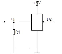
1. Pull-up Resistor Circuit
A pull-up resistor circuit is shown in the figure, which is an inverter in a digital circuit. When no low level is injected into the input terminal Ui of the inverter, the pull-up resistor R1 can make the input terminal stable at a high level, preventing the low-level interference that will cause the inverter to malfunction.
If there is no pull-up resistor, the input terminal of the inverter is suspended, so the external low-level interference will easily enter the inverter, thereby causing the inverter to flip in the direction of the output high level.

2. Pull-down Resistor Circuit
The figure shows the inverter in the digital circuit. The input terminal Ui is grounded through the pull-down resistor R1 so that when there is no high-level input, the input terminal can be stable at a low level without the high-level interference that causes the inverter to malfunction.
If the pull-down resistor R1 is omitted, the input end of the inverter is floating and at high impedance. As a result, the external high-level interference is easily added to the inverter from the input, making the inverter turn over in the direction of the output low level.
Recommended Articles:
Analysis of Resistors in Series and Parallel
 UTMEL
UTMEL
We are the professional distributor of electronic components, providing a large variety of products to save you a lot of time, effort, and cost with our efficient self-customized service. careful order preparation fast delivery service
1.What is pull up and pull down resistor?
A pull-up resistor connects unused input pins (AND and NAND gates) to the dc supply voltage, (Vcc) to keep the given input HIGH. A pull-down resistor connects unused input pins (OR and NOR gates) to ground, (0V) to keep the given input LOW.
2.When to use pull up or pull down resistors?
Pull-up and pull-down resistors are often used when interfacing a switch or some other input with a microcontroller or other digital gates. Most microcontrollers have in-built programmable pull up/down resistors so fewer external components are needed.
3.What are pull up pull down resistors used for?
In electronic logic circuits, a pull-up resistor or pull-down resistor is a resistor used to ensure a known state for a signal. It is typically used in combination with components such as switches and transistors, which physically interrupt the connection of subsequent components to ground or to VCC.
4.How does a pull down resistor work?
The pull-down resistor holds the logic signal near to zero volts (0V) when no other active device is connected. It pulls the input voltage down to the ground to prevent an undefined state at the input. It should have a larger resistance than the impedance of the logic circuit.
5.Why are resistors grounded?
The resistor provides a path to ground for these stray electrons. To avoid grounding out the input, the resistance is set sufficiently high so that only a very small amount of the input current follows the path (current divider) to ground.
 What are the Differences Between Pull up and Pull down Resistors?UTMEL22 October 202539172
Pull up is to clamp an uncertain signal to a high level with a resistor, and the resistor also acts as a current limiter. In the same way, pull down means to clamp the uncertain signal to a low level through a resistor. To pull up is to input current to the device, and the pull-down is to output the current.
Read More Rheostat Basics: Types, Principle and FunctionsUTMEL25 December 202518808
A rheostat is a device that can adjust the size of the resistance and can be connected to the circuit to adjust the size of the current. A general rheostat is composed of a wire with a larger resistance and a device that can change the contact point to adjust the effective length of the resistance wire. Rheostat can limit the current and protect the circuit, and change the voltage distribution in the circuit.
Read More Basic Introduction to Metal Film ResistorUTMEL28 August 202014047
Metal film resistors are a kind of film resistors. Metal film resistors are resistors in which special metals or alloys are used as resistor materials, and the resistor film layer is basically formed on ceramic or glass by vacuum evaporation or sputtering.
Read More Varistor: Definition, Function, Working and TestingUTMEL03 April 202584448
A varistor is a device with a non-linear volt-ampere characteristic. When the voltage applied to the varistor is lower than its threshold value, the current flowing through it is extremely small, which is equivalent to a resistor with infinite resistance, vice versa. The most common varistor is a metal oxide varistor (MOV).
Read More Photoresistor Basics: Types, Principles and ApplicationsUTMEL16 October 202547020
The article introduces the photoresistor’s main characteristics and principles including the working principle and structural principle. There are three types of photoresistor: ultraviolet photoresistors, infrared photoresistors, visible light photoresistors. Dimming circuit and light switch are the two applications of the photoresistor.
Read More
Subscribe to Utmel !
![SKY65045-70LF]() SKY65045-70LF
SKY65045-70LFSkyworks Solutions Inc.
![SKY65404-31]() SKY65404-31
SKY65404-31Skyworks Solutions Inc.
![ADF5904ACPZ]() ADF5904ACPZ
ADF5904ACPZAnalog Devices Inc.
![HMC578LC3BTR]() HMC578LC3BTR
HMC578LC3BTRAnalog Devices Inc.
![HMC634]() HMC634
HMC634Analog Devices Inc.
![ADRF6703ACPZ-R7]() ADRF6703ACPZ-R7
ADRF6703ACPZ-R7Analog Devices Inc.
![HMC741ST89E]() HMC741ST89E
HMC741ST89EAnalog Devices Inc.
![13FR050E]() 13FR050E
13FR050EOhmite
![TDA7706CB]() TDA7706CB
TDA7706CBSTMicroelectronics
![HMC451LP3TR]() HMC451LP3TR
HMC451LP3TRAnalog Devices Inc.


