
 Product
 Brand
Brand Articles
 Tools
Tools
Photoresistor Basics: Types, Principles and Applications

Light Dependent Resistors (LDR): Working Principle
Last Updated: October 2025 | This article has been revised to reflect current technology and industry standards.
Abstract
There are three types of photoresistors: ultraviolet photoresistors, infrared photoresistors, and visible light photoresistors. Commonly used materials include cadmium sulfide (CdS), cadmium selenide (CdSe), lead sulfide (PbS), and newer cadmium-free alternatives developed for environmental compliance. The working principle of the photoresistor is based on the internal photoelectric effect. Photoresistors are formed by mounting electrode leads at both ends of semiconductor photosensitive material and encapsulating them in a housing with a transparent window. Applications include dimming circuits, automatic lighting controls, light switches, and IoT-enabled smart lighting systems.
Table of Contents
I. Introduction
The photoresistor, also known as a light-dependent resistor (LDR) or photoconductor, is a passive semiconductor component whose resistance varies inversely with the intensity of incident light. Common materials used in photoresistor manufacturing include cadmium sulfide (CdS), cadmium selenide (CdSe), lead sulfide (PbS), and lead selenide (PbSe). These materials exhibit the characteristic that their resistance value decreases rapidly under irradiation by light of specific wavelengths. This occurs because photon-generated carriers participate in conduction and undergo drift movement under the influence of an external electric field. Electrons move toward the positive terminal while holes move toward the negative terminal, thereby reducing the photoresistor's overall resistance.
The photoresistor is a specialized resistor made from semiconductor materials such as sulfides or selenides, operating on the principle of the internal photoelectric effect. As light intensity increases, the resistance value decreases rapidly, with bright resistance values potentially dropping below 1 kΩ. Photoresistors are highly sensitive to light; in darkness, they exhibit high resistance states with dark resistance typically reaching 1.5 MΩ or higher.
Photoresistors function based on the photoconductive effect in semiconductors, where resistance changes according to incident light intensity. They are classified as photoconductive detectors. Generally, as incident light intensity increases, resistance decreases, though some specialized variants exhibit inverse behavior.
Common applications include light measurement, light-activated control systems, and photoelectric conversion (transforming light variations into electrical signal changes). The cadmium sulfide (CdS) photoresistor remains widely used due to its spectral sensitivity closely matching human vision (approximately 0.4 to 0.76 μm in the visible spectrum). This characteristic greatly simplifies light control circuit design when using incandescent lamps or natural light as control sources.
2025 Update: Due to RoHS (Restriction of Hazardous Substances) regulations in many regions, cadmium-based photoresistors are being phased out in consumer electronics. Alternative materials such as organic photoconductive polymers and silicon-based photodetectors are increasingly common in new designs.
II. Specifications
Photoresistors are typically manufactured in a planar structure to maximize light energy absorption. When illuminated, electron-hole pairs are excited in the semiconductor photosensitive layer, participating in conduction and increasing circuit current. To achieve high sensitivity, photoresistor electrodes commonly employ an interdigitated (comb-like) pattern, formed by vapor-depositing metals such as gold, indium, or aluminum onto the photoconductive film through a mask.

Figure 2. Structure of a general photoresistor
A typical photoresistor consists of the following components:
Photosensitive layer: The active semiconductor material
Substrate: Glass or ceramic base (modern versions may use FR4 PCB material)
Protective coating: Epoxy resin or moisture-resistant film
Electrodes: Metal contacts for electrical connection
In circuit diagrams, photoresistors are represented by the letters "R," "RL," or "RG" with a photoresistor symbol.
Cadmium sulfide (CdS) photoresistors are available in two main package types:
Epoxy resin package: Available in various diameters (Ø3mm, Ø4mm, Ø5mm, Ø7mm, Ø11mm, Ø12mm, Ø20mm, Ø25mm) based on ceramic substrate size
Metal package: More durable for industrial applications
Both packages are available in through-hole (DIP) format, though surface-mount (SMD) variants have become increasingly common in modern electronics.
III. Parameters & Characteristics
Photoresistors are classified by their spectral characteristics into three main types: ultraviolet photoresistors, infrared photoresistors, and visible light photoresistors.
1. Main Parameters
(1) Photocurrent and Bright Resistance: Under a specified applied voltage, photocurrent flows when the device is illuminated. The ratio of applied voltage to photocurrent defines the bright resistance, typically expressed as resistance at "100 lux" illumination.
(2) Dark Current and Dark Resistance: Under a specified applied voltage without illumination, the photoresistor conducts a small dark current. The ratio of applied voltage to dark current defines the dark resistance, typically expressed as resistance at "0 lux." Dark resistance generally ranges from 1 MΩ to over 10 MΩ depending on the device.
(3) Sensitivity: Sensitivity represents the relative change between dark resistance (no illumination) and bright resistance (under illumination). It is often expressed as the ratio: Sensitivity = (Dark Resistance - Bright Resistance) / Bright Resistance.
(4) Spectral Response: Also called spectral sensitivity, this parameter describes the photoresistor's sensitivity under monochromatic light at different wavelengths. Plotting sensitivity versus wavelength produces the spectral response curve, which is critical for application-specific design.
(5) Illumination Characteristics: These characteristics describe how the electrical output varies with illumination intensity. As light intensity increases, resistance decreases rapidly initially, then the rate of change diminishes, eventually plateauing. This relationship is typically non-linear.
(6) Volt-Ampere Characteristic Curve: Under constant illumination, this curve shows the relationship between applied voltage and resulting current. At a given bias voltage, higher light intensity produces greater photocurrent. However, voltage cannot be increased indefinitely—each photoresistor has rated power, maximum operating voltage, and rated current limits. Exceeding these specifications may cause permanent damage.
(7) Temperature Coefficient: The photoelectric effect is significantly influenced by temperature. Many photoresistors exhibit higher sensitivity at lower temperatures and reduced sensitivity at elevated temperatures. Typical operating ranges are -30°C to +70°C, though specialized variants can operate at extremes.
(8) Rated Power: This specifies the maximum power the photoresistor can dissipate safely. As temperature increases, allowable power consumption decreases. Common ratings range from 50 mW to 300 mW.
(9) Response Time: The time required for resistance to change from initial darkness to 90% of its final illuminated value. CdS photoresistors typically have response times of 10-100 milliseconds, making them unsuitable for high-speed applications.
2. Frequency Characteristics
When illuminated with pulsed light, photoresistors require time to reach stable photocurrent values. After illumination ceases, photocurrent does not immediately return to zero—this is the time delay characteristic. Different photosensitive materials exhibit varying delay characteristics and frequency responses. Lead sulfide (PbS) photoresistors operate at much higher frequencies than cadmium sulfide (CdS) types, though most photoresistors have relatively slow response times, limiting their use in applications requiring rapid response (typically unsuitable for frequencies above 1 kHz).
IV. How Does the Photoresistor Work?
1. Working Principle
Photoresistors operate based on the internal photoelectric effect. They are constructed by attaching electrode leads to both ends of semiconductor photosensitive material and encapsulating the assembly in a housing with a transparent window. To maximize sensitivity, the two electrodes are often configured in an interdigitated comb pattern.
Manufacturing materials primarily include metal sulfides, selenides, and tellurides. Thin photoresistive films and interdigitated ohmic electrodes are deposited onto insulating substrates using techniques such as coating, spraying, or sintering. Lead wires are attached and the device is sealed in a moisture-resistant housing with a light-transmitting window to maintain sensitivity.
When incident light ceases, photon-excited electron-hole pairs recombine, and the photoresistor's resistance returns to its original value. When voltage is applied across the metal electrodes, current flows through the device. Upon illumination with light of appropriate wavelength, current increases proportionally with light intensity, achieving photoelectric conversion.
Photoresistors have no polarity and function as purely resistive devices, compatible with both DC and AC voltages. The conductivity of semiconductors depends on the carrier concentration in the conduction band. When photons with sufficient energy strike the semiconductor, they excite electrons from the valence band to the conduction band, creating electron-hole pairs that increase conductivity and decrease resistance.
2. Structural Principle
Photoresistors are specialized resistors fabricated from sulfide or selenide semiconductor materials. The surface is coated with moisture-resistant resin providing photoconductive effects. The working principle relies on the internal photoelectric effect: electrode leads are mounted at both ends of the semiconductor photosensitive material and sealed in a transparent-windowed housing. To enhance sensitivity, electrodes are arranged in an interdigitated configuration.
Semiconductor conductivity depends on carrier concentration in the conduction band. Under illumination, valence band electrons absorb photon energy and transition to the conduction band, becoming free electrons while simultaneously creating holes. These electron-hole pairs reduce resistivity. Greater light intensity generates more photocarriers, further reducing resistance. When voltage is applied across the photoresistor, current increases with illumination intensity. When light is removed, electron-hole pairs gradually recombine, resistance returns to its original value, and current decreases accordingly.
Photoresistors are highly light-sensitive. In darkness, they exhibit high resistance (dark resistance typically 1.5 MΩ or higher). Under illumination, free electrons and holes are excited within the material, decreasing resistance. As light intensity increases, resistance drops rapidly, with bright resistance potentially falling below 1 kΩ.
Illumination characteristics are non-linear in most operating ranges, exhibiting linearity only within limited ranges. Photoresistor resistance values show considerable variation (resistance changes exhibit significant range irregularity).
Sensitivity refers to the relative change between dark resistance (without illumination) and bright resistance (under illumination). The dark-to-bright resistance ratio typically ranges from 100:1 to 1000:1 or higher. Larger dark resistance is generally preferable. Either DC or AC bias voltage can be applied to photoresistors. CdS photoresistors are well-suited for visible light applications and are commonly used in automatic control circuits, photoelectric counting, photoelectric tracking, light-controlled lamps, camera automatic exposure systems, and television automatic brightness control circuits.
V. Classification
By Semiconductor Material:
Intrinsic photoresistors: Made from pure semiconductor materials
Doped photoresistors: Contain added impurities for enhanced performance and stability (more commonly used due to superior characteristics)
By Spectral Response:
1. Ultraviolet Photoresistors: Most sensitive to ultraviolet radiation. Materials include cadmium sulfide (CdS) and cadmium selenide (CdSe), though these also respond to visible light. True UV-specific photoresistors use materials like zinc oxide (ZnO) or gallium nitride (GaN).
2. Infrared Photoresistors: Primarily composed of lead sulfide (PbS), lead telluride (PbTe), lead selenide (PbSe), and indium antimonide (InSb). These devices are extensively used in missile guidance systems, astronomical observation, non-contact temperature measurement, medical diagnostics, infrared spectroscopy, infrared communication, and various defense, scientific research, and industrial applications.
3. Visible Light Photoresistors: Include selenium (Se), cadmium sulfide (CdS), cadmium selenide (CdSe), cadmium telluride (CdTe), gallium arsenide (GaAs), silicon (Si), germanium (Ge), and zinc sulfide (ZnS) based devices. Applications span photoelectric control systems such as automatic door opening/closing, navigation and street light automatic switching, automatic water supply controls, mechanical protection devices, position detectors, camera automatic exposure systems, photoelectric counters, smoke detectors, photoelectric tracking systems, and smart home lighting controls.
2025 Update: Modern photoresistor applications increasingly incorporate IoT connectivity, enabling smart home integration and remote monitoring capabilities. Additionally, perovskite-based photoresistors are emerging as promising alternatives with improved response times and broader spectral sensitivity.
VI. Applications
Photoresistors are semiconductor light-sensitive devices offering high sensitivity, fast response speed (relative to human perception), good spectral characteristics, and excellent consistency. They maintain stability and reliability even in harsh environments with high temperature and humidity variations. Applications include cameras, solar garden lights, lawn lights, currency validators, quartz clocks, musical greeting cards, gift boxes, night lights, sound-and-light-activated switches, automatic street lighting controls, and various light-controlled toys, lighting fixtures, and automatic switching control applications.
1. Dimming Circuit
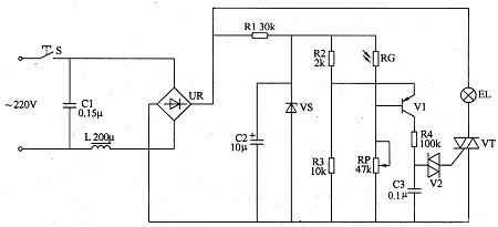
Figure 4. Typical light-control dimming circuit
A typical light-controlled dimming circuit operates as follows: when ambient light weakens, the photoresistor's resistance increases, raising the voltage applied to the capacitor C and consequently increasing the voltage across the lamp. Conversely, when ambient light brightens, the photoresistor's resistance decreases, reducing the thyristor's conduction angle and the voltage across the lamp.
Important Note: The rectifier bridge in such circuits must provide pulsating DC voltage and should not be filtered into smooth DC voltage using a capacitor, as this would prevent proper thyristor operation.
2. Light Switch
Various light-controlled switch circuits using photoresistors as core components exist, including self-locking bright activation, dark activation, precision light activation, and precision dark activation configurations.
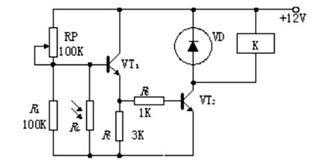
Figure 5. Simple dark-excitation relay switching circuit
Simple Dark-Activation Relay Switch: When illumination drops to a preset threshold, the photoresistor's resistance increases, turning on transistor VT1. This provides base current to VT2, energizing the relay. The normally open contact closes and the normally closed contact opens, enabling control of external circuits.
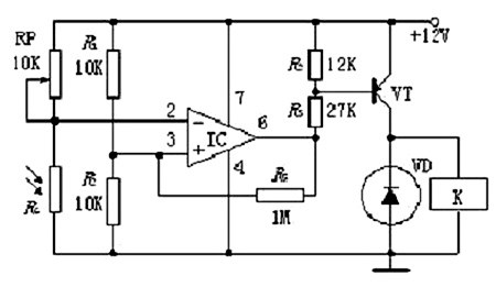
Figure 6. Precision dark-excitation time delay relay switch circuit
Precision Dark-Activation Time-Delay Relay Switch: When illumination falls to the set value, the operational amplifier's inverting terminal potential increases due to rising photoresistor resistance. The op-amp output activates transistor VT, which energizes the relay. The normally open contact closes while the normally closed contact opens, controlling the external circuit.
Modern Alternative: Contemporary designs often replace relays with solid-state switches (MOSFETs or IGBTs) for faster switching, longer life, and silent operation. Microcontroller-based designs enable programmable thresholds and sophisticated lighting schedules.
VII. Advantages and Disadvantages
Advantages
(1) Based on internal photoelectric effect independent of electrodes (unlike photodiodes), allowing DC power supply operation
(2) Sensitivity correlates with semiconductor material and incident light wavelength
(3) Epoxy coating provides good reliability
(4) Compact size and small footprint
(5) Wide sensitivity adjustment range
(6) Good spectral characteristics matching application requirements
(7) Low cost compared to photodiodes and phototransistors
(8) No external bias required for operation
(9) High dark resistance enables low standby power consumption
Disadvantages
(1) Poor linearity of photoelectric conversion under strong illumination
(2) Extended photoelectric relaxation process: photoconductivity gradually increases during illumination and decreases gradually after light cessation
(3) Very low frequency response (inability to detect rapidly changing light signals)
(4) Significant temperature sensitivity affecting performance
(5) Slow response speed ranging from milliseconds to seconds, with delay time influenced by incident light intensity (photodiodes do not exhibit this limitation and offer higher sensitivity)
(6) Limited spectral response compared to modern silicon photodetectors
(7) Response time variation based on illumination history (memory effect)
(8) Aging effects can alter characteristics over time
VIII. Environmental Considerations
As of 2025, environmental regulations have significantly impacted photoresistor manufacturing and application:
RoHS Compliance: The European Union's Restriction of Hazardous Substances directive restricts the use of cadmium in electronic equipment. While exemptions exist for certain applications, manufacturers are developing cadmium-free alternatives.
Alternative Materials: Research into environmentally friendly photoresistive materials includes organic semiconductors, quantum dots, and silicon-based photoconductors.
Recycling: Proper disposal and recycling procedures are essential for cadmium-containing devices to prevent environmental contamination.
Lifecycle Considerations: Modern designs increasingly consider the entire product lifecycle, from material sourcing through end-of-life disposal.
Industry Trend: Many consumer electronics manufacturers have transitioned to photodiodes, phototransistors, or alternative photodetectors to achieve RoHS compliance while maintaining or improving performance characteristics.
IX. Conclusion
Photoresistors remain important photoelectric conversion elements despite competition from more advanced photodetectors. With the rapid development of electronic information technology and increasingly stringent performance requirements, photoresistor applications continue to evolve. Modern manufacturing automation has significantly improved production efficiency and consistency.
While traditional cadmium-based photoresistors face regulatory challenges, ongoing research into alternative materials ensures the technology's continued relevance. Applications in simple light-sensing scenarios, educational projects, and cost-sensitive designs maintain demand for these devices. However, designers should carefully evaluate application requirements—considering factors such as response time, spectral sensitivity, environmental regulations, and cost—when selecting between photoresistors and alternative photodetection technologies.
The future of photoresistor technology lies in developing environmentally compliant materials, improving response characteristics, and integrating with smart systems and IoT platforms. As the technology matures, photoresistors will continue serving applications where their unique combination of simplicity, reliability, and cost-effectiveness provides optimal solutions.
Related Topics:
Variable Resistors and Potentiometers
Photodiodes and Phototransistors
Light Sensing in Modern Electronics
Smart Lighting Control Systems
RoHS Compliance in Electronic Components
Article Updated: October 2025 | Original Publication: 2020
 UTMEL
UTMEL
We are the professional distributor of electronic components, providing a large variety of products to save you a lot of time, effort, and cost with our efficient self-customized service. careful order preparation fast delivery service
1 Who invented the Photoresistor?
Willoughby Smith The idea of Photoresistor developed when photoconductivity in Selenium was discovered by Willoughby Smith in 1873. Many variants of the photoconductive devices were then made.
2 Is Photoresistor analog or digital?
A photo-resistor is fundamentally an analog component. They are usually used with a series fixed resistor to make a variable voltage source.
3 Is LDR active or passive?
A photoresistor (LDR for Light Decreasing Resistance, or light-dependent resistor, or photo-conductive cell) is a passive component that decreases resistance with respect to receiving luminosity (light) on the component's sensitive surface.
4 Is photodiode and LDR the same?
LDR is a light-dependent resistance, the photoresistor is identical to LDR, but the photodiode is a diode connected in inverse polarization whose conduction varies according to the light. a photodiode can measure very small changes in light intensity. it can even be used to detect different light colors.
5 What devices use LDRs?
These resistors are used as light sensors and the applications of LDR mainly include alarm clocks, street lights, light intensity meters, burglar alarm circuits.
 What are the Differences Between Pull up and Pull down Resistors?UTMEL22 October 202538073
Pull up is to clamp an uncertain signal to a high level with a resistor, and the resistor also acts as a current limiter. In the same way, pull down means to clamp the uncertain signal to a low level through a resistor. To pull up is to input current to the device, and the pull-down is to output the current.
Read More Rheostat Basics: Types, Principle and FunctionsUTMEL25 December 202517817
A rheostat is a device that can adjust the size of the resistance and can be connected to the circuit to adjust the size of the current. A general rheostat is composed of a wire with a larger resistance and a device that can change the contact point to adjust the effective length of the resistance wire. Rheostat can limit the current and protect the circuit, and change the voltage distribution in the circuit.
Read More Basic Introduction to Metal Film ResistorUTMEL28 August 202013755
Metal film resistors are a kind of film resistors. Metal film resistors are resistors in which special metals or alloys are used as resistor materials, and the resistor film layer is basically formed on ceramic or glass by vacuum evaporation or sputtering.
Read More Varistor: Definition, Function, Working and TestingUTMEL03 April 202583287
A varistor is a device with a non-linear volt-ampere characteristic. When the voltage applied to the varistor is lower than its threshold value, the current flowing through it is extremely small, which is equivalent to a resistor with infinite resistance, vice versa. The most common varistor is a metal oxide varistor (MOV).
Read More Photoresistor Basics: Types, Principles and ApplicationsUTMEL16 October 202545399
The article introduces the photoresistor’s main characteristics and principles including the working principle and structural principle. There are three types of photoresistor: ultraviolet photoresistors, infrared photoresistors, visible light photoresistors. Dimming circuit and light switch are the two applications of the photoresistor.
Read More
Subscribe to Utmel !
![TDA7705TR]() TDA7705TR
TDA7705TRSTMicroelectronics
![AD607ARSZ-REEL]() AD607ARSZ-REEL
AD607ARSZ-REELAnalog Devices Inc.
![LMV221SDX/NOPB]() LMV221SDX/NOPB
LMV221SDX/NOPBTexas Instruments
![HMC942LP4E]() HMC942LP4E
HMC942LP4EAnalog Devices Inc.
![CC1150RGVT]() CC1150RGVT
CC1150RGVTTexas Instruments
![TRF372017IRGZR]() TRF372017IRGZR
TRF372017IRGZRTexas Instruments
![SST12LP17E-XX8E]() SST12LP17E-XX8E
SST12LP17E-XX8EMicrochip Technology
![TDA7786CTR]() TDA7786CTR
TDA7786CTRSTMicroelectronics
![TRF3722IRGZT]() TRF3722IRGZT
TRF3722IRGZTTexas Instruments
![ATA5746C-PXQW-1]() ATA5746C-PXQW-1
ATA5746C-PXQW-1Microchip Technology


