Resistor Symbols: From Circuit Diagrams to PCB Design
Contents
1.0 Introduction
Whether you're deciphering complex circuit diagrams or designing your very first PCB, understanding the language of electronic components is the first step. And among these symbols, resistor symbols are undoubtedly one of the most fundamental and crucial. Have you ever found yourself puzzled by the squiggly lines or rectangles in a schematic? You're not alone. The world of electronics relies heavily on these graphical representations to convey vital information about how components interact and function within a circuit.
So, what exactly is a resistor symbol? Simply put, it's a standardized graphical representation used in circuit diagrams to denote the presence and type of a resistor. Understanding these symbols is paramount for anyone involved in electronics, from hobbyists to seasoned engineers. They form the bedrock for accurate circuit analysis, efficient design, and effective troubleshooting and repair. Without a clear grasp of these symbols, navigating even the simplest electronic schematics would be an impossible task.
In this comprehensive guide, we will embark on a journey to demystify resistor symbols. We'll cover everything from the two primary international standards—IEC and ANSI—to the specific symbols for various resistor types, including fixed, variable, thermistors, and LDRs. We'll also delve into practical applications, showing you how to locate and utilize these symbols in popular EDA software like Eagle and KiCad. Finally, we'll provide you with a valuable, downloadable quick-reference chart to keep at your fingertips. By the end of this article, you'll be able to confidently interpret any electronic resistor symbol meaning and enhance your understanding of circuit diagram principles.
2.0 The Fundamentals: Two Major International Standards
When it comes to representing resistors in circuit diagrams, two major international standards dominate the landscape: the International Electrotechnical Commission (IEC) and the American National Standards Institute (ANSI). While both serve the same purpose—to visually represent a resistor—they do so with distinct graphical conventions. Understanding these differences is key to interpreting schematics from various regions and historical contexts. This section will clarify the standard resistor symbols explained: IEC vs. ANSI.
2.1 The IEC Resistor Symbol (The Rectangle)
The IEC (International Electrotechnical Commission) resistor symbol is characterized by a simple, elongated rectangle. This symbol is widely adopted across Europe and many other parts of the world, serving as the international standard for electronic schematics. Its clean, minimalist design makes it easily recognizable and universally understood within the global electronics community. The IEC standard is part of IEC 60617, which defines graphical symbols for diagrams.

IEC Resistor Symbol - Image Source: Wikipedia
2.2 The ANSI Resistor Symbol (The Zig-Zag)
In contrast, the ANSI (American National Standards Institute) resistor symbol is represented by a zig-zag line. This symbol is predominantly used in the United States and some parts of Asia. Its distinctive zig-zag shape is often preferred by those who find it more visually intuitive in representing resistance, perhaps evoking the idea of an electrical path with obstacles. The ANSI standard is defined by ANSI Y32 / IEEE 315.
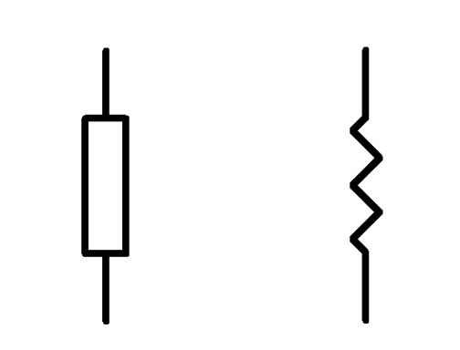
ANSI Resistor Symbol- Image Source: JAK Electronics
2.3 Quick Comparison: European vs. American Resistor Symbols
To provide a clear visual distinction between the two, here's a quick comparison of the European vs American resistor symbols:
| Feature | IEC Resistor Symbol | ANSI Resistor Symbol |
|---|---|---|
| Appearance | Rectangle | Zig-zag line |
| Usage | Europe, International | USA, Parts of Asia |
| Standard | IEC 60617 | ANSI Y32 / IEEE 315 |
Both symbols effectively convey the presence of a resistor, but their regional prevalence means you'll encounter both in your electronic endeavors. Consistency within a single schematic is crucial, regardless of which standard is chosen.
3.0 Reading Resistor Symbols in Circuit Diagrams
Understanding how to interpret resistor symbols in circuit diagrams is fundamental to comprehending the function of any electronic circuit. These diagrams are essentially the blueprints of electronic systems, and resistors play a critical role in controlling current flow and voltage distribution. This section will guide you through identifying and understanding resistor symbols within a schematic.
When you look at a circuit diagram, you'll typically see various symbols interconnected by lines representing wires. The resistor symbol, whether IEC or ANSI, will be present to indicate where a resistor is placed. Often, these symbols are accompanied by alphanumeric designators and values.
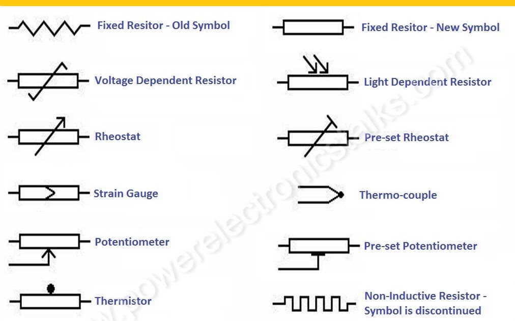
Image Source: Power Electronics Talks
For instance, you might see R1, R2, or R_LOAD next to a resistor symbol. The 'R' signifies that the component is a resistor, and the number (e.g., '1', '2') is a unique identifier within that specific circuit. This helps in referencing specific components when discussing or troubleshooting the circuit. Below the designator, or sometimes next to it, you'll find the resistor's value, typically expressed in ohms (Ω), kilohms (kΩ), or megohms (MΩ). For example, 10kΩ indicates a 10,000-ohm resistor.
The deeper electronic resistor symbol meaning lies in its function: it represents a component that opposes the flow of electrical current. This opposition, known as resistance, is crucial for various circuit operations, such as limiting current to protect sensitive components, dividing voltage, or setting time constants in RC circuits. The symbol visually communicates this fundamental property within the circuit's flow.
3.1 How to Read Resistor Symbols in Datasheets
Beyond circuit diagrams, resistor symbols also appear in datasheets, which are technical documents providing detailed specifications for electronic components. In datasheets, the symbol is usually presented alongside critical component specifications such as power rating (e.g., 0.25W, 1W), tolerance (e.g., ±1%, ±5%), temperature coefficient, and physical dimensions. This comprehensive presentation helps engineers select the appropriate resistor for their specific application. Understanding how to read resistor symbols in datasheets involves correlating the symbol with these detailed electrical and physical parameters.
4.0 Beyond the Basics: A Deep Dive into Different Resistor Types
While the fixed resistor is the most common, the world of resistors extends far beyond a single type. Various specialized resistors exist, each designed for specific applications and represented by unique schematic symbols. This section will provide a resistor schematic symbols list, exploring common and specialized resistor types.
4.1 Fixed Resistor vs. Variable Resistor Symbols
Fixed resistors, as discussed, have a constant resistance value. Variable resistors, on the other hand, allow their resistance to be adjusted. This adjustability is indicated by an arrow or a diagonal line passing through the base resistor symbol.
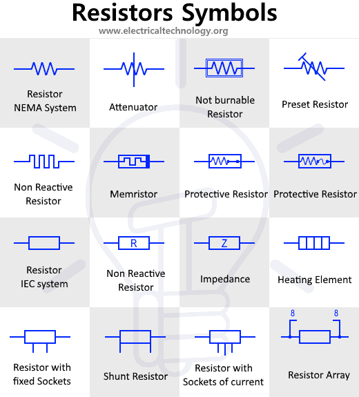
Image Source: Electrical Technology
This arrow is the key to variable resistor symbol identification. It signifies that the resistance can be changed, either manually or by some external factor.
4.2 Potentiometers and Rheostats: The Kings of Variable Resistance
Potentiometers and rheostats are specific types of variable resistors. While often confused, they serve distinct purposes and have slightly different symbols.
Potentiometer: A three-terminal variable resistor primarily used as a voltage divider. Its symbol typically shows the base resistor with an arrow pointing to the resistive element, indicating a movable contact (wiper).

Image Source: Wikipedia
Understanding the potentiometer symbol in electronics is crucial for circuits requiring adjustable voltage outputs, such as volume controls or sensor interfaces.
Rheostat: A two-terminal variable resistor used to control current by varying its resistance in series with a load. Its symbol is often similar to a variable resistor, but sometimes depicted with only two terminals and an arrow.
4.3 Specialized Resistor Symbols: Thermistors, LDRs, and Varistors
Beyond general variable resistors, several specialized resistors respond to specific environmental changes, each with its own unique symbol:
Thermistor Symbol: A thermistor is a type of resistor whose resistance is highly dependent on temperature. Its symbol often resembles a standard resistor with a 'T' or a diagonal line and a temperature-dependent curve, distinguishing it from a regular resistor. This helps in understanding the thermistor symbol vs resistor symbol.
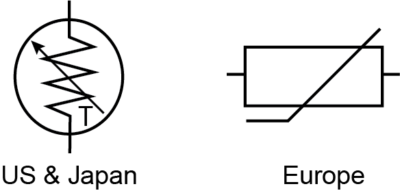
Thermistor Symbol - Image Source: Wavelength Electronics
LDR (Photoresistor): A Light-Dependent Resistor, or photoresistor, changes its resistance based on the intensity of light falling upon it. Its symbol typically includes the standard resistor symbol enclosed in a circle, with arrows pointing towards it, representing light.

LDR Symbol Image Source: Starting Electronics
Varistor (VDR): A Voltage-Dependent Resistor, or varistor, has a resistance that varies with applied voltage. Its symbol often includes the standard resistor symbol with a 'V' or a diagonal line indicating voltage dependency.
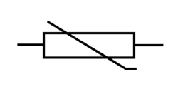
Varistor Symbol - Image Source: Wikipedia
4.4 Physical Packages: SMD Resistor vs. Through-Hole Symbols
While the schematic symbols for SMD (Surface Mount Device) and through-hole resistors are generally identical in principle diagrams, it's important to note that their physical representations in PCB layout views (footprints) are vastly different. The schematic symbol represents the electrical function, while the footprint represents the physical dimensions and solder pads required for manufacturing. This distinction is important when considering SMD resistor symbol vs through-hole in the context of actual PCB design.
5.0 Practical Application: Resistor Symbols in EDA Software
For anyone designing electronic circuits, understanding how to find and use resistor symbols in Electronic Design Automation (EDA) software is a practical necessity. This section will guide you through the process in two popular EDA tools: KiCad and Eagle PCB.
5.1 Locating the Resistor Symbol in KiCad
KiCad is a free and open-source EDA suite widely used for schematic capture and PCB layout. To add a resistor symbol in KiCad's schematic editor:
Open the schematic editor.
Click on the
“Place Symbol” tool (usually represented by a gate symbol or a component icon).
In the component search dialog, type
Rorresistor. You will see various resistor symbols, including generic fixed resistors (e.g.,R), variable resistors (e.g.,POTfor potentiometer), and specialized types.Select the desired resistor symbol (e.g.,
Rfor a generic fixed resistor) and place it on your schematic.
This process directly addresses the common search query: resistor symbol in KiCad.
5.2 Working with Resistor Symbols in Eagle PCB
Eagle (Easily Applicable Graphical Layout Editor) is another popular EDA software, now part of Autodesk. Here’s how you typically work with resistor symbols in Eagle:
Open the schematic editor.
Click on the “ADD” icon (often looks like a gate or component).
In the “Add Part” dialog, navigate through the libraries or use the search function. Resistors are typically found in libraries like
resistor.lbrorrcl.lbr.Search for
R-US(for ANSI zig-zag) orR-EU(for IEC rectangle) for fixed resistors, orPOTfor potentiometers. Select the appropriate symbol and place it.
Understanding these steps is crucial for users searching for resistor symbols in Eagle PCB.
6.0 Your Go-To Resource: Printable Resistor Symbols Chart
To make your journey through electronics even smoother, we’ve compiled a comprehensive, easy-to-read, and printable resistor symbols chart. This valuable resource includes all the major resistor symbols discussed in this guide, from the fundamental IEC and ANSI representations to specialized types like thermistors and LDRs. It’s designed to be your quick-reference companion, whether you’re in the lab, at your workbench, or simply studying schematics.
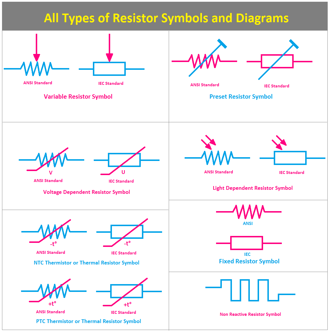
Printable Resistor Symbols Chart - Image Source: ETechnoG
This chart directly fulfills the search need for a resistor symbols chart printable. It’s an invaluable tool for students, hobbyists, and professionals alike, ensuring you always have the correct symbol at your fingertips.
7.0 Frequently Asked Questions - FAQ
We understand that mastering electronic symbols can come with its own set of questions. Here, we address some of the most common queries about resistor symbols to further solidify your understanding.
Q1: What are the two main symbols for a resistor?
The two main symbols for a resistor are the IEC rectangle (International Electrotechnical Commission) and the ANSI zig-zag (American National Standards Institute). These are the most widely recognized and used representations in circuit diagrams globally.
Q2: What does an arrow through a resistor symbol mean?
An arrow through a resistor symbol signifies a variable resistor. This indicates that the resistance value of the component can be adjusted. Examples include potentiometers and rheostats, which allow for manual control over resistance.
Q3: Is a potentiometer symbol the same as a variable resistor?
A potentiometer is indeed a type of variable resistor. While the general variable resistor symbol shows an arrow through a fixed resistor symbol, the potentiometer symbol is more specific, typically featuring three terminals to represent its function as a voltage divider. So, while related, its three-terminal symbol is a specific variation of the general variable resistor symbol.
Q4: Which resistor symbol should I use in my schematics?
The choice of resistor symbol (IEC or ANSI) largely depends on your audience and regional conventions. For international projects or modern designs, the IEC symbol (rectangle) is often preferred due to its widespread adoption. For US-centric or older schematics, the ANSI symbol (zig-zag) is common. The most important rule is consistency within a single schematic to avoid confusion.
Q5: Where can I find a complete list of electronic symbols?
For a comprehensive list of electronic symbols, you can refer to international standards such as IEC 60617 (Graphical symbols for diagrams). Additionally, many online resources and electronics textbooks provide extensive symbol libraries. For example, you can explore resources like Wikipedia's list of electronic symbols or other reputable electronics education websites.
8.0 Conclusion
We’ve journeyed through the fascinating world of resistor symbols, from their fundamental representations in IEC and ANSI standards to the specialized symbols for various resistor types. We’ve explored how to interpret these symbols in circuit diagrams, understand their deeper meanings, and even how to practically apply this knowledge in popular EDA software. The ability to confidently read and understand these symbols is not just a technical skill; it’s a gateway to unlocking the full potential of electronic design and troubleshooting.
Understanding these symbols is paramount for any electronics enthusiast or professional. They are the universal language that allows us to communicate complex circuit designs efficiently and accurately. By mastering them, you gain a powerful tool for innovation and problem-solving in the ever-evolving field of electronics.
We encourage you to download our free printable resistor symbols chart to keep this essential knowledge at your fingertips. What other symbols have you encountered that puzzled you? Share your experiences or any other symbol-related questions in the comments section below! And don’t forget to explore our other related content, such as “How to Read Resistor Color Codes” to further enhance your electronics expertise.
Further Reading:
 What are the Differences Between Pull up and Pull down Resistors?UTMEL22 October 202534375
Pull up is to clamp an uncertain signal to a high level with a resistor, and the resistor also acts as a current limiter. In the same way, pull down means to clamp the uncertain signal to a low level through a resistor. To pull up is to input current to the device, and the pull-down is to output the current.
Read More Rheostat Basics: Types, Principle and FunctionsUTMEL25 December 202515649
A rheostat is a device that can adjust the size of the resistance and can be connected to the circuit to adjust the size of the current. A general rheostat is composed of a wire with a larger resistance and a device that can change the contact point to adjust the effective length of the resistance wire. Rheostat can limit the current and protect the circuit, and change the voltage distribution in the circuit.
Read More Basic Introduction to Metal Film ResistorUTMEL28 August 202011359
Metal film resistors are a kind of film resistors. Metal film resistors are resistors in which special metals or alloys are used as resistor materials, and the resistor film layer is basically formed on ceramic or glass by vacuum evaporation or sputtering.
Read More Varistor: Definition, Function, Working and TestingUTMEL03 April 202580480
A varistor is a device with a non-linear volt-ampere characteristic. When the voltage applied to the varistor is lower than its threshold value, the current flowing through it is extremely small, which is equivalent to a resistor with infinite resistance, vice versa. The most common varistor is a metal oxide varistor (MOV).
Read More Photoresistor Basics: Types, Principles and ApplicationsUTMEL16 October 202541763
The article introduces the photoresistor’s main characteristics and principles including the working principle and structural principle. There are three types of photoresistor: ultraviolet photoresistors, infrared photoresistors, visible light photoresistors. Dimming circuit and light switch are the two applications of the photoresistor.
Read More
Subscribe to Utmel !
![PIC12LF1840T39AT-I/ST]() PIC12LF1840T39AT-I/ST
PIC12LF1840T39AT-I/STMicrochip Technology
![CC1310F128RSMT]() CC1310F128RSMT
CC1310F128RSMTTexas Instruments
![LT5515EUF#PBF]() LT5515EUF#PBF
LT5515EUF#PBFLinear Technology/Analog Devices
![SI4463-C2A-GMR]() SI4463-C2A-GMR
SI4463-C2A-GMRSilicon Labs
![SI4713-B30-GM]() SI4713-B30-GM
SI4713-B30-GMSilicon Labs
![CC3200MODR1M2AMOBT]() CC3200MODR1M2AMOBT
CC3200MODR1M2AMOBTTexas Instruments
![ADF7021BCPZ]() ADF7021BCPZ
ADF7021BCPZAnalog Devices Inc.
![MC13213]() MC13213
MC13213NXP USA Inc.
![CC2564CRVMT]() CC2564CRVMT
CC2564CRVMTTexas Instruments
![SI4438-B1C-FMR]() SI4438-B1C-FMR
SI4438-B1C-FMRSilicon Labs


