
 Product
 Brand
Brand Articles
 Tools
Tools
How to read Resistors Color Code?
How to Read a Resistor?
Abstract
Resistor color codes are a standardized system used to identify the resistance value, tolerance, and sometimes the temperature coefficient of resistors. This system, governed by the international standard IEC 60062, uses a series of colored bands painted on the resistor body. Whether a resistor has three, four, five, or six bands, this visual coding allows for quick identification of its electrical characteristics from any angle. This is why color-banded resistors, such as carbon film, metal film, and metal oxide film types, are ubiquitous in electronic equipment. This updated guide for 2025 will provide a comprehensive overview of how to read resistor color codes, introduce modern marking systems like those for Surface-Mount Devices (SMDs), and offer tips to avoid common identification errors.
Catalog
I. How to Determine the Reading Direction

Figure 1. Resistors with color codes
Before you can read a resistor's value, you must know which direction to read the bands. This can sometimes be confusing, but a few simple tricks make it straightforward:
Tip 1: Look for the Tolerance Band. The tolerance band is usually gold or silver and is almost always the last band on the right. If you see a gold or silver band, orient the resistor so that this band is on your right-hand side. This is the most reliable method for orienting 4-band resistors.
Tip 2: Check the Band Spacing. Often, the space between the multiplier band and the tolerance band is wider than the space between the other bands. This larger gap indicates the end of the significant digits and multiplier, so the band after the gap is the tolerance band (and should be on the right).
Tip 3: Use the E-Series to Eliminate Impossible Values. If you are still unsure, try reading the resistor in both directions. One direction will likely result in a standard resistance value that belongs to an E-series (e.g., E6, E12, E24), while the other will produce a non-standard value. For example, a resistor with bands Brown-Black-Black-Yellow-Brown could be 100 x 10k = 1MΩ with 1% tolerance (a standard value) or 140 x 1 = 140Ω with 1% tolerance (not a standard value). The correct reading is 1MΩ.
II. Reading Color-Banded Resistors
Once oriented correctly, you can read the resistance value. The system is based on two parts: the significant digits and the multiplier.

Figure 2. Resistor bands explained
1. Three-Band Resistors
Three-band resistors are less common today and typically have a high tolerance. The first two bands represent the significant digits, and the third band is the multiplier. The tolerance is assumed to be ±20%.
2. Four-Band Resistors
This is the most common type of resistor. The first two bands are the significant digits, the third is the multiplier, and the fourth is the tolerance.
Example: Brown-Red-Red-Gold
The resistance is 12 x 100 = 1,200Ω or 1.2kΩ, with a tolerance of ±5%.
3. Five-Band Resistors
Used for higher precision, five-band resistors have three significant digits. The first three bands are the significant digits, the fourth is the multiplier, and the fifth is the tolerance.
Example: Red-Red-Black-Brown-Gold
The resistance is 220 x 10 = 2,200Ω or 2.2kΩ, with a tolerance of ±5%.
4. Six-Band Resistors
Six-band resistors are high-precision resistors that add a sixth band to indicate the Temperature Coefficient of Resistance (TCR). The first three bands are the significant digits, the fourth is the multiplier, the fifth is the tolerance, and the sixth is the TCR.
III. Resistor Color Code Chart (IEC 60062)

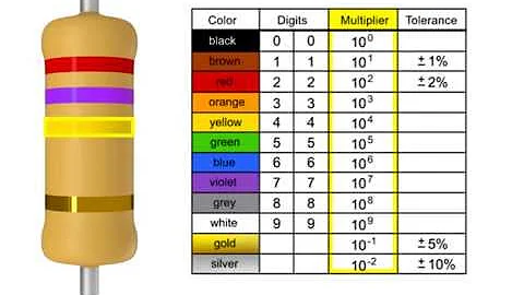
Figure 3. Resistor color code chart
The table below shows the standard values for each color as defined by IEC 60062.
| Color | Significant Digit | Multiplier | Tolerance | TCR (ppm/K) |
|---|---|---|---|---|
| Black | 0 | x1 | - | 250 |
| Brown | 1 | x10 | ±1% | 100 |
| Red | 2 | x100 | ±2% | 50 |
| Orange | 3 | x1,000 | ±0.05% | 15 |
| Yellow | 4 | x10,000 | ±0.02% | 25 |
| Green | 5 | x100,000 | ±0.5% | 20 |
| Blue | 6 | x1,000,000 | ±0.25% | 10 |
| Violet | 7 | x10,000,000 | ±0.1% | 5 |
| Grey | 8 | x100,000,000 | ±0.01% | 1 |
| White | 9 | x1,000,000,000 | - | - |
| Gold | - | x0.1 | ±5% | - |
| Silver | - | x0.01 | ±10% | - |
| None | - | - | ±20% | - |
IV. Reading Examples
Example 1 (4-Band): Yellow-Violet-Red-Gold
Significant digits: 4 (Yellow), 7 (Violet)
Multiplier: x100 (Red)
Tolerance: ±5% (Gold)
Calculation: 47 x 100 = 4,700Ω or 4.7kΩ, with a tolerance of ±5%.
Example 2 (5-Band): Orange-Orange-Black-Brown-Brown
Significant digits: 3 (Orange), 3 (Orange), 0 (Black)
Multiplier: x10 (Brown)
Tolerance: ±1% (Brown)
Calculation: 330 x 10 = 3,300Ω or 3.3kΩ, with a tolerance of ±1%.
Example 3 (6-Band): Red-Green-Blue-Yellow-Brown-Red
Significant digits: 2 (Red), 5 (Green), 6 (Blue)
Multiplier: x10,000 (Yellow)
Tolerance: ±1% (Brown)
TCR: 50 ppm/K (Red)
Calculation: 256 x 10,000 = 2,560,000Ω or 2.56MΩ, with a tolerance of ±1% and a TCR of 50 ppm/K.
V. Beyond Color Bands: SMD Resistor Codes
Modern electronics increasingly use Surface-Mount Devices (SMDs) due to their small size. These resistors are too small for color bands and use a numerical code instead.
Three- and Four-Digit System: The first two or three digits represent the significant figures, and the last digit is the multiplier (power of 10). For example, a resistor marked "472" is 47 x 100 = 4.7kΩ. A resistor marked "1001" is 100 x 10 = 1kΩ. The letter 'R' is used to indicate a decimal point (e.g., 4R7 = 4.7Ω).
EIA-96 System: This system is used for 1% tolerance SMD resistors and consists of a three-character code. The first two digits are a code representing the three significant digits of the resistance value, and the letter is a multiplier. For example, "01A" means 100 x 1 = 100Ω.
VI. Common Mistakes and Helpful Tools
Even with a clear chart, mistakes can happen. Here are some common pitfalls:
Misinterpreting Colors: Poor lighting can make it difficult to distinguish between colors like red/orange or blue/green. Always work in a well-lit area.
Reading Direction: Reading the bands in the wrong order is a frequent error. Remember to place the tolerance band (usually gold or silver) on the right.
When in doubt, the most reliable tool is a multimeter. It can measure the resistance directly and confirm your reading. Additionally, many free online calculators and mobile apps are available to quickly verify resistor values from their color codes.
 UTMEL
UTMEL
We are the professional distributor of electronic components, providing a large variety of products to save you a lot of time, effort, and cost with our efficient self-customized service. careful order preparation fast delivery service
1.How do you read resistor color codes?
Hold the resistor with these grouped bands to your left. Always read resistors from left to right. - Resistors never start with a metallic band on the left. If you have a resistor with a gold or silver band on one end, you have a 5% or 10% tolerance resistor.
2.What is the color code of 100 ohm resistor?
100 Ohm Resistor Color Code: Brown, Black, Black, Black, Brown.
3.What is color code?
A color code or colour code is a system for displaying information by using different colors. The use of color codes has been extended to abstractions, such as the Homeland Security Advisory System color code in the United States.
4.What do the colors on resistors mean?
The colour code used to denote the tolerance rating of a resistor is given as: Brown = 1%, Red = 2%, Gold = 5%, Silver = 10 % If resistor has no fourth tolerance band then the default tolerance would be at 20%.
5.What does a 10k resistor look like?
A 10k ohm resistor has 4 color band: brown, black, orange, and gold for 5% tolerance, respectively. A 1k ohm resistor has 4 color band: brown, black, red, and gold for 5% tolerance, respectively.
 What are the Differences Between Pull up and Pull down Resistors?UTMEL22 October 202538073
Pull up is to clamp an uncertain signal to a high level with a resistor, and the resistor also acts as a current limiter. In the same way, pull down means to clamp the uncertain signal to a low level through a resistor. To pull up is to input current to the device, and the pull-down is to output the current.
Read More Rheostat Basics: Types, Principle and FunctionsUTMEL25 December 202517815
A rheostat is a device that can adjust the size of the resistance and can be connected to the circuit to adjust the size of the current. A general rheostat is composed of a wire with a larger resistance and a device that can change the contact point to adjust the effective length of the resistance wire. Rheostat can limit the current and protect the circuit, and change the voltage distribution in the circuit.
Read More Basic Introduction to Metal Film ResistorUTMEL28 August 202013755
Metal film resistors are a kind of film resistors. Metal film resistors are resistors in which special metals or alloys are used as resistor materials, and the resistor film layer is basically formed on ceramic or glass by vacuum evaporation or sputtering.
Read More Varistor: Definition, Function, Working and TestingUTMEL03 April 202583287
A varistor is a device with a non-linear volt-ampere characteristic. When the voltage applied to the varistor is lower than its threshold value, the current flowing through it is extremely small, which is equivalent to a resistor with infinite resistance, vice versa. The most common varistor is a metal oxide varistor (MOV).
Read More Photoresistor Basics: Types, Principles and ApplicationsUTMEL16 October 202545398
The article introduces the photoresistor’s main characteristics and principles including the working principle and structural principle. There are three types of photoresistor: ultraviolet photoresistors, infrared photoresistors, visible light photoresistors. Dimming circuit and light switch are the two applications of the photoresistor.
Read More
Subscribe to Utmel !
![TDA7705TR]() TDA7705TR
TDA7705TRSTMicroelectronics
![AD607ARSZ-REEL]() AD607ARSZ-REEL
AD607ARSZ-REELAnalog Devices Inc.
![LMV221SDX/NOPB]() LMV221SDX/NOPB
LMV221SDX/NOPBTexas Instruments
![HMC942LP4E]() HMC942LP4E
HMC942LP4EAnalog Devices Inc.
![CC1150RGVT]() CC1150RGVT
CC1150RGVTTexas Instruments
![TRF372017IRGZR]() TRF372017IRGZR
TRF372017IRGZRTexas Instruments
![SST12LP17E-XX8E]() SST12LP17E-XX8E
SST12LP17E-XX8EMicrochip Technology
![TDA7786CTR]() TDA7786CTR
TDA7786CTRSTMicroelectronics
![TRF3722IRGZT]() TRF3722IRGZT
TRF3722IRGZTTexas Instruments
![ATA5746C-PXQW-1]() ATA5746C-PXQW-1
ATA5746C-PXQW-1Microchip Technology


