Product
 Brand
Brand Articles
 Tools
Tools
Classification of Current Sensors
Catalog
Ⅰ Introduction
Modern power equipment has incorporated increasingly sophisticated technologies to meet the demands of efficiency, safety, and precision. Technologies such as switching power supplies, hard and soft switching, voltage stabilization, linear feedback voltage regulation, magnetic amplifier technology, digital voltage regulation, PWM (Pulse Width Modulation), SPWM (Sinusoidal Pulse Width Modulation), and electromagnetic compatibility have become standard in power supply design. These advancements have been driven by practical demands, continuously pushing power supply technology forward.
To enable automatic detection and display of current, modern power supply technology increasingly relies on sensor-based detection, sampling, and protection mechanisms. Current sensors, also known as magnetic sensors, have emerged as essential components and are gaining favor among power supply designers. These sensors find applications across diverse fields including household appliances, smart grids, electric vehicles, wind power generation, solar inverters, industrial automation, and energy storage systems.
Magnetic sensors are ubiquitous in our daily lives—from computer hard drives and smartphones to compasses, household appliances, and automotive systems. As of 2025, the global current sensor market continues to expand rapidly, driven by the electrification of transportation, renewable energy adoption, and the proliferation of IoT (Internet of Things) devices requiring precise current monitoring.
Ⅱ Classification of Current Sensors
With continuous technological advancement, current sensors have evolved significantly. According to different measurement principles, current sensors can be classified into several main categories: shunts, electromagnetic current transformers, and electronic current transformers. Electronic current transformers include Hall effect sensors, Rogowski coil sensors, fluxgate sensors, and fiber-optic current sensors.
Compared with traditional electromagnetic current sensors, electronic current transformers offer several advantages: no ferromagnetic saturation, wide transmission frequency bandwidth, minimal secondary load requirements, compact size, and lightweight construction. These characteristics make them the preferred choice for future current sensing applications.
Fiber-optic current sensors represent a cutting-edge technology based on the Faraday magneto-optical effect, using optical fiber as the transmission medium. When linearly polarized light propagates through a medium in the presence of a strong magnetic field parallel to the light's propagation direction, the polarization plane rotates. The rotation angle ψ is proportional to both the magnetic flux density B and the length l of the light path through the medium: ψ = V·B·l, where V is the Verdet constant, which depends on the medium's properties and the light wavelength. This phenomenon, discovered by Michael Faraday in 1845, forms the basis for non-contact, high-precision current measurement in fiber-optic sensors.
1 Shunt
A current shunt is a precision resistor used primarily for DC current measurement, operating on Ohm's law principle: when current flows through a resistor, a proportional voltage drop is generated across it. Modern shunts are manufactured using materials such as manganin, constantan, or specialized alloys that exhibit low temperature coefficients and excellent long-term stability.
Advantages: High accuracy (typically 0.1% to 0.5%), fast response time (nanosecond range), low cost, simple implementation, and excellent linearity. Disadvantages: No electrical isolation between measurement and measured circuits, power dissipation as heat, limited to DC and low-frequency AC measurements, and potential safety concerns in high-voltage applications.
Shunts are particularly suitable for low-frequency and moderate current measurements in applications such as battery management systems, DC power supplies, and electronic test equipment. The resistance value is typically very small (milliohms to microohms) to minimize power loss and circuit interference. For accurate measurements, the ratio between the shunt current and the meter's full-scale deflection current must be precisely calibrated, ensuring optimal linearity and reading accuracy.
2 Fluxgate Current Sensor
Fluxgate current sensors utilize the nonlinear magnetization characteristics of high-permeability magnetic cores under saturation excitation by an alternating magnetic field. When subjected to an external magnetic field (generated by the measured current), the magnetic flux density in the core exhibits a nonlinear relationship with the magnetic field intensity.
The operating principle can be visualized as a "gate" that modulates the magnetic flux from the environment. This modulation generates an induced electromotive force (EMF) that is proportional to the external magnetic field. By measuring this induced voltage, the sensor can indirectly determine the current flowing through a conductor.
Fluxgate sensors offer exceptional sensitivity and can detect extremely weak magnetic fields, making them ideal for precision applications requiring high resolution. They are commonly used in aerospace, geophysical exploration, and high-precision current measurement systems. Modern fluxgate sensors can achieve noise levels below 10 pT/√Hz and operate effectively from DC to several kHz.
3 Current Transformer
A current transformer (CT) is an instrument that transforms a large primary current into a proportionally smaller secondary current based on electromagnetic induction principles. It is exclusively used for AC current measurement and consists of a closed magnetic core and primary and secondary windings.
The primary winding, with relatively few turns, is connected in series with the conductor carrying the current to be measured. Under normal operating conditions, the voltage drop across both windings is minimal, effectively operating as a short-circuit transformer with very low core flux. The magnetomotive forces (MMF) of the primary and secondary windings are equal in magnitude but opposite in direction: F₁ = F₂, or I₁N₁ = I₂N₂. Therefore, the current ratio is inversely proportional to the turns ratio: I₁/I₂ = N₂/N₁.
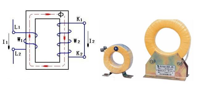
Figure 1. Schematic diagram and physical diagram of current transformer
Critical Safety Warning: The secondary circuit of a current transformer must never be left open during operation. If the secondary circuit opens, the primary current becomes purely magnetizing current, causing the core flux and secondary voltage to increase dramatically—potentially reaching dangerous levels that can damage equipment, destroy insulation, and pose serious safety hazards to personnel.
The technical explanation: When current I₁ flows through the primary winding (N₁ turns), it generates magnetomotive force F₁ = I₁N₁, producing flux Φ₁ in the core. The secondary current I₂ through N₂ turns generates opposing magnetomotive force F₂ = I₂N₂ and flux Φ₂. The net core flux is Φ = Φ₁ + Φ₂. Since Φ₁ and Φ₂ are opposite and nearly equal, the net flux Φ ≈ 0 under normal conditions. If the secondary opens (I₂ = 0), then Φ = Φ₁, causing excessive core saturation and inducing dangerously high voltage E₂ in the secondary winding.
For this reason, current transformers must have their secondary terminals short-circuited before disconnecting any measuring instruments, and one terminal of the secondary winding must be grounded to prevent dangerous voltage buildup. Additionally, fuses should never be installed in the secondary circuit, as they could open under fault conditions and create a hazardous situation.
Modern current transformers are available in various configurations including wound, bar, and window types, with accuracy classes ranging from 0.1 to 10, suitable for metering, protection, and measurement applications in power systems up to several hundred kilovolts.
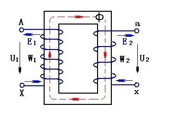
Figure 2. Schematic diagram of voltage transformer
4 Hall Sensor
Electronic current transformers, including Hall effect sensors, Rogowski coils, and specialized variable frequency power sensors, offer significant advantages over traditional electromagnetic current sensors. These include absence of ferromagnetic saturation, wide frequency bandwidth (DC to several MHz), minimal secondary loading, compact dimensions, and lightweight construction—making them the preferred choice for modern applications.
The Hall effect, discovered by Edwin Hall in 1879, occurs when charge carriers in a conductive material move through an external magnetic field. The carriers experience a Lorentz force perpendicular to both their velocity and the magnetic field, causing them to deflect and accumulate on opposite sides of the material. This charge accumulation creates an electric field that eventually balances the Lorentz force, establishing a stable potential difference—the Hall voltage (VH)—across the material.
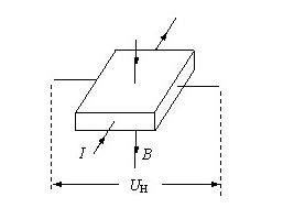
Figure 3. Hall effect principle
Hall current sensors apply both the Hall effect and Ampère's law: a current-carrying conductor generates a magnetic field proportional to the current. By positioning a Hall element to measure this magnetic field, non-contact current measurement is achieved. The Hall voltage VH is given by: VH = (RH · I · B) / t, where RH is the Hall coefficient, I is the bias current, B is the magnetic flux density, and t is the thickness of the Hall element.
Modern Hall sensors incorporate integrated signal conditioning circuits that amplify the typically small Hall voltage (millivolts) to usable output levels (0-5V, 4-20mA, or digital protocols). Advanced implementations include temperature compensation, offset nulling, and programmable gain to enhance accuracy and stability.
Advantages: Can measure both DC and AC currents, wide frequency response (DC to 100+ kHz in standard versions, up to several MHz in specialized designs), excellent electrical isolation, good linearity, and relatively compact size. Disadvantages: Slower response to transients compared to Rogowski coils, reduced accuracy at very low currents (typically >1A for optimal performance), temperature sensitivity requiring compensation, and higher cost than simple shunts.
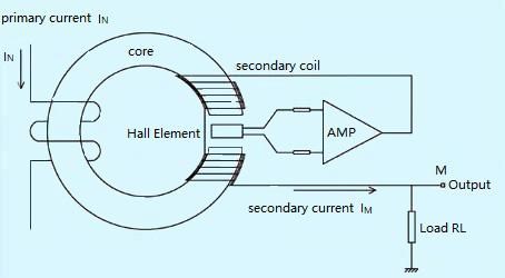
Figure 4. Closed-loop (zero-flux) Hall current sensor
Figure 4 illustrates a closed-loop (zero-flux or compensated) Hall current sensor, which achieves superior performance through magnetic field compensation. The operating principle: when primary current IP flows through the conductor, it generates magnetic flux in the magnetic core that is detected by the Hall element. The Hall element's output drives a compensation circuit that generates secondary current IS through a multi-turn winding. This secondary current produces a magnetic field opposing the primary field, driving the net flux toward zero.
In this zero-flux configuration, the Hall element acts as a null detector rather than a direct measurement device. When magnetic equilibrium is achieved: IP · NP = IS · NS, where NP and NS are the primary and secondary turns (typically NP = 1). The measured current is then proportional to the compensation current: IP = (NS/NP) · IS.
This closed-loop approach offers significant advantages: higher accuracy (typically 0.5-1%), better linearity (<0.1%), wider bandwidth (DC to 200 kHz), improved temperature stability, and faster response time (typically <1 μs). The dynamic balance is maintained continuously—any disturbance in the primary current immediately triggers a compensating adjustment in the secondary current, restoring equilibrium within microseconds.
5 Rogowski Coil
The Rogowski coil, invented by Walter Rogowski and W. Steinhaus in 1912, is an air-core toroidal coil used for measuring AC current. Unlike traditional current transformers, it has no magnetic core, which eliminates saturation effects and provides a truly linear response over an extremely wide current range.
The coil consists of a helical winding on a non-magnetic former, typically arranged in a toroidal shape that can be opened and closed around a conductor. According to Faraday's law, the voltage induced in the coil is proportional to the rate of change of current: Vout = M · (dI/dt), where M is the mutual inductance between the conductor and the coil.
Advantages: Excellent linearity over wide current ranges (milliamps to hundreds of kiloamps), no saturation, very fast response (nanosecond rise times), lightweight and flexible construction, easy installation on existing conductors, and inherently safe due to low energy storage. Disadvantages: Output requires integration (analog or digital) to obtain current waveform, cannot measure DC current, sensitive to external magnetic fields without proper shielding, and requires careful positioning for accuracy.
Modern Rogowski coils incorporate integrated electronics for signal conditioning and are widely used in power quality analyzers, protection relays, high-current switching applications, and transient current measurement in power electronics. They are particularly valuable in applications involving high di/dt rates, such as short-circuit testing and pulse power systems.
Comparison of Current Sensing Technologies
From an application perspective, current transformers and Hall sensors share the requirement of magnetic field generation, but differ fundamentally in operation. Current transformers require a time-varying magnetic field and thus work only with AC, while Hall sensors respond to static fields and can measure both DC and AC.
Current transformers utilize ferromagnetic cores, resulting in nonlinear frequency response and limiting their effective bandwidth (typically 45-66 Hz for power frequency applications, or up to several kHz for specialized designs). Hall sensors, being coreless in their sensing element, offer linear frequency response from DC to over 100 kHz.
Traditional current transformers are primarily used for energy metering where phase accuracy is critical (phase error specifications at 50/60 Hz are essential). Hall sensors are predominantly used for control, monitoring, and protection applications where absolute phase accuracy is less critical, though modern designs increasingly specify phase performance.
The choice of current sensing technology depends on specific application requirements including: current magnitude and type (AC/DC), frequency range, accuracy requirements, isolation needs, size constraints, environmental conditions, cost considerations, and safety requirements.
Ⅲ The Future Development Trends of Current Sensors
1. Enhanced Sensitivity and Resolution
As electronic systems become more sophisticated, the need to detect increasingly weak signals continues to grow. Modern applications require current sensors with dramatically improved sensitivity, capable of resolving microampere-level currents while maintaining accuracy. This trend is driven by applications in IoT devices, wearable electronics, medical implants, precision instrumentation, and energy harvesting systems. Advanced magnetic sensing technologies, including TMR (Tunnel Magnetoresistance) and GMR (Giant Magnetoresistance) sensors, are achieving sensitivity levels previously unattainable, with noise floors below 1 nT/√Hz.
2. Superior Temperature Stability
Operating environments for sensors are becoming increasingly demanding, with temperature ranges extending from -40°C to +150°C or beyond in automotive and industrial applications. Modern current sensors must maintain accuracy and stability across these extreme conditions. Advanced compensation techniques, including digital calibration, multi-point temperature correction, and temperature-stable materials (such as zero-TCR resistive alloys), are being implemented. Automotive electronics, particularly in electric vehicles where sensors must operate reliably in engine compartments and battery packs, represent a major driver for this development. Aerospace and industrial automation also demand exceptional temperature performance.
3. Robust Electromagnetic Immunity
In many applications, sensors operate in electrically noisy environments with strong electromagnetic interference (EMI) from switching power supplies, motor drives, wireless communications, and other sources. Current sensors must exhibit excellent immunity to these disturbances while maintaining measurement accuracy. Advanced shielding techniques, differential sensing architectures, digital signal processing, and frequency-selective filtering are employed to achieve robust performance. Critical applications include automotive electronics (especially in EVs with high-power inverters), industrial motor drives, renewable energy systems, and smart grid infrastructure.
4. Miniaturization, Integration, and Intelligence
The trend toward smaller, more integrated solutions continues to accelerate. Modern current sensors increasingly incorporate multiple functions into single packages, including signal conditioning, analog-to-digital conversion, digital communication interfaces (I²C, SPI, CAN), self-diagnostics, and even edge computing capabilities. System-in-Package (SiP) and System-on-Chip (SoC) approaches enable chip-level integration, while module-level integration combines sensing elements with power management and communication circuits. Intelligent sensors with built-in microcontrollers can perform local data processing, implement adaptive calibration, detect anomalies, and communicate via IoT protocols. This integration reduces system complexity, improves reliability, and enables predictive maintenance capabilities.
5. Extended Bandwidth and High-Frequency Performance
As power electronics switching frequencies increase (now commonly exceeding 100 kHz, with SiC and GaN devices enabling MHz operation), current sensors must provide accurate measurements at these elevated frequencies. Wide-bandgap semiconductor adoption in motor drives, EV inverters, and renewable energy converters demands sensors with bandwidth extending from DC to several MHz. Applications also include high-speed data acquisition, power quality monitoring, active filter control, and transient analysis. Rogowski coils, wideband Hall sensors, and emerging technologies like magnetoresistive sensors address these requirements.
6. Ultra-Low Power Consumption
Battery-powered and energy-harvesting applications demand sensors with minimal power consumption to extend operational lifetime. Modern current sensors achieve sub-milliwatt operation through advanced circuit design, duty-cycled operation, and energy-efficient sensing principles. Critical applications include implantable medical devices (pacemakers, neurostimulators), wireless sensor networks, portable instruments, smart meters, and IoT edge devices. Some designs achieve operational currents below 10 μA in sleep modes while maintaining rapid wake-up capability for periodic measurements.
7. Enhanced Safety and Isolation
As electrical systems operate at higher voltages (EVs at 800V+, industrial systems at kilovolts), galvanic isolation becomes increasingly critical for safety and regulatory compliance. Modern current sensors provide reinforced or double isolation ratings exceeding 5 kV, meeting stringent safety standards (IEC 61010, UL 61010, VDE 0884). Isolation technologies include optical, capacitive, and magnetic coupling, with working voltages up to 1500V DC and surge immunity to 12 kV or higher. Functional safety certifications (ISO 26262 for automotive, IEC 61508 for industrial) are becoming standard requirements.
8. Wireless and IoT Connectivity
The proliferation of IoT and Industry 4.0 drives demand for current sensors with integrated wireless communication capabilities. Modern sensors incorporate Bluetooth Low Energy (BLE), Wi-Fi, LoRaWAN, NB-IoT, or other wireless protocols, enabling remote monitoring, cloud connectivity, and integration into smart building management systems, industrial automation networks, and energy management platforms. Edge computing capabilities allow local data processing, reducing bandwidth requirements and enabling real-time decision-making.
9. Wide Dynamic Range and Multi-Range Capability
Modern applications often require measurement of currents spanning several orders of magnitude—from standby microamperes to peak currents of hundreds of amperes. Advanced current sensors incorporate auto-ranging capabilities, programmable gain, and wide dynamic range (>120 dB) to accommodate these requirements without manual range switching. This is particularly important in battery management systems, motor control, and power quality monitoring where load conditions vary dramatically.
10. Environmental Sustainability
As environmental regulations tighten and sustainability becomes a priority, current sensor manufacturers are focusing on RoHS and REACH compliance, lead-free manufacturing, reduced material usage, and recyclability. Energy-efficient designs that minimize power consumption throughout the product lifecycle contribute to overall system sustainability. Additionally, sensors enabling better energy management in buildings, industrial processes, and transportation systems play a crucial role in global decarbonization efforts.
Recommended Articles:
 UTMEL
UTMEL
We are the professional distributor of electronic components, providing a large variety of products to save you a lot of time, effort, and cost with our efficient self-customized service. careful order preparation fast delivery service
How does a current sensor work?
When current flows through a conductor, it creates a proportional magnetic field around the conductor. The sensor then outputs a certain voltage or current that a meter connected to the sensor can read and translate into the amount of current flowing through the conductor.
What is the purpose of a current sensor?
A current sensor is a device that detects and converts current to an easily measured output voltage, which is proportional to the current through the measured path. When a current flows through a wire or in a circuit, voltage drop occurs. Also, a magnetic field is generated surrounding the current carrying conductor.
What are the different current sensors available in market?
The current sensor market, by type (1), is segmented into open-loop and closed-loop current sensors. The open-loop current sensors are expected to witness significant growth in the market during the forecast period as they provide a cost advantage over a closed-loop sensor in high current ranges (over 100 A).
What is DC current sensor?
The CTLC series current transducers are Hall-effect current sensors with signal conditioning and an output amplifier in a single compact package. ... Hall-effect current measurement is a non-contact technique that measures the magnetizing effects of current flowing in a conductor.
What is current sensor module?
ACS712 Current Sensor Module - 20A is based on ACS712 sensor, which can accurately detect AC or DC current. The maximum AC or DC that can be detected can reach 20A, and the present current signal can be read via analog I / O port of a microcontroller or an Arduino.
 The Key Role of Electronic Components in IoT DevicesUTMEL01 September 20235793
The article discusses the pivotal role of electronic components in Internet of Things (IoT) devices. IoT devices work by capturing real-world data using sensors, processing it through a microcontroller, and then sending it to the cloud for further analysis.
Read More Accelerometer Sensors Guide: Working Principle, Circuit Design, Specifications, and ApplicationsUTMEL25 June 2026176
A practical accelerometer sensor guide covering working principles, MEMS and piezoelectric types, datasheet specifications, circuit design, mounting, applications, and selection.
Read More How to Identify the Perfect Proximity Sensor for Your ApplicationUTMEL19 July 20251701
Find the best proximity sensors for your project by evaluating material, sensing range, environment, and system needs to ensure optimal performance and reliability.
Read More Trusted Vibration Sensors for Homeowners and Industry ProfessionalsUTMEL17 July 20251348
Compare top vibration sensors for home and industrial use. Find trusted options for security, predictive maintenance, and equipment protection.
Read More Wiring and Mounting Photoelectric Sensors in 2025UTMEL15 July 20251546
Wire and mount photoelectric sensors in 2025 with step-by-step safety, wiring, and alignment tips for reliable installation and optimal sensor performance.
Read More
Subscribe to Utmel !