Product
 Brand
Brand Articles
 Tools
Tools
What are Weight Sensors?
Catalog
I What are Weight Sensors?
A weight sensor, also commonly known as a load cell, is a transducer device that converts mass or force into a measurable electrical signal output. These sensors are fundamental components in modern weighing systems, from industrial scales to precision laboratory instruments. When selecting a weight sensor, the actual working environment must be carefully considered, as this directly impacts the sensor's performance, accuracy, reliability, safety, and service life. The choice of sensor also affects the overall reliability and safety of the entire weighing system.
II Classification of Weight Sensors
Weight sensors can be classified according to their conversion principles into several main categories. As of 2025, the most widely used type remains the resistance strain gauge sensor, though digital and smart sensors are gaining significant market share due to their enhanced accuracy and connectivity features.
1. Photoelectric Weight Sensor
Photoelectric sensors include optical grating type and code disc type configurations.
Optical grating sensors utilize moiré fringes formed by gratings to convert angular displacement into photoelectric signals. The system consists of two gratings: one fixed and one movable grating mounted on the dial axis. When a test object is placed on the load-bearing platform, it rotates the dial shaft through the transmission lever system, driving the moving grating to rotate and causing the moiré fringe pattern to move accordingly. Using photocells, conversion circuits, and display instruments, the number of moiré fringes can be counted to measure the grating's rotation angle and determine the mass of the measured object.
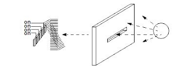
Figure 2. Moiré Fringe Effect
The code wheel sensor uses a transparent glass disc mounted on the dial shaft with black and white codes compiled according to a specific encoding method. When the test object rotates the dial shaft through the force transmission lever, the code wheel rotates proportionally. Photocells receive optical signals through the code wheel and convert them into electrical signals, which are then digitally processed by the circuit to display the measured mass. While photoelectric weight sensors were primarily used in electromechanical combined scales, they have largely been replaced by more accurate digital systems in modern applications.
2. Hydraulic Weight Sensor
When the gravitational force P of the measured object acts on the sensor, the pressure of the hydraulic oil increases proportionally to P. By measuring this pressure increase, the mass of the object can be determined. Hydraulic weight sensors feature a simple, robust structure and large measuring range, but their accuracy typically does not exceed 1/100 (1%). They are particularly suitable for harsh environments and heavy-duty applications where extreme durability is required.
3. Capacitive Weight Sensor
Capacitive sensors operate on the proportional relationship between the oscillation frequency f of a capacitor oscillation circuit and the electrode plate distance d. The system consists of two electrode plates: one fixed and one movable. When a test object is placed on the load-bearing platform, the leaf spring deflects, changing the distance between the two electrode plates and consequently altering the circuit's oscillation frequency. By measuring this frequency change, the object's mass can be determined. Capacitive weight sensors consume minimal power and are cost-effective, with accuracy ranging from 1/200 to 1/500 (0.5% to 0.2%).
4. Electromagnetic Force Weight Sensor
This sensor type uses the principle that the load on the load-bearing platform is balanced by an electromagnetic force. When the test object is placed on the platform, one end of the lever tilts upward. A photoelectric component detects this tilt signal, which is amplified and fed into a coil to generate an electromagnetic force that restores the lever to equilibrium. By digitally converting the current that generates the electromagnetic balance force, the measured object's mass can be determined. Electromagnetic force weight sensors offer high accuracy, ranging from 1/2000 to 1/60000 (0.05% to 0.0017%), but their weighing range is typically limited to between tens of milligrams and 10 kilograms. These sensors are commonly used in precision analytical balances and laboratory applications.
5. Magnetic Pole Variation Weight Sensor
When a ferromagnetic element undergoes mechanical deformation under the gravity of the measured object, internal stress is generated, changing the material's permeability. This causes the induced voltage of the secondary coil wound on both sides of the ferromagnetic element (magnetic pole) to change accordingly. By measuring the voltage change, the force applied to the magnetic pole can be determined, and thus the object's mass. Magnetic pole variation weight sensors have moderate accuracy, generally around 1/100 (1%), with weighing ranges from tens to tens of thousands of kilograms, making them suitable for large tonnage weighing applications.
6. Vibrating Weight Sensor
When force is applied to an elastic element, its natural vibration frequency becomes proportional to the square root of the applied force. By measuring the change in natural frequency, the force exerted by the measured object on the elastic element can be determined, and subsequently its mass. There are two main types of vibrating sensors: vibrating wire and tuning fork.
The elastic element of a vibrating wire sensor is a tensioned wire. When an object is placed on the load-bearing platform, the intersection point of the V-shaped string is pulled down, increasing the tension in the left string and decreasing it in the right string. The natural frequencies of the two strings change differently. By calculating the difference between these two frequencies, the object's mass can be obtained.
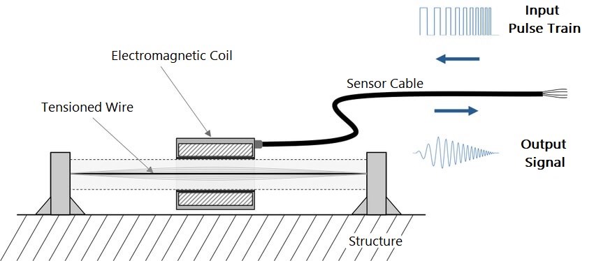
Figure 3. Structure of Vibrating Wire Sensors
Vibrating wire sensors offer high accuracy, up to 1/1000-1/10000 (0.1% to 0.01%), with weighing ranges from 100 grams to several hundred kilograms. However, these sensors have complex structures, are difficult to manufacture, and have high production costs.
The elastic element of the tuning fork sensor is a tuning fork structure. A piezoelectric element is fixed at the end of the tuning fork, which oscillates at the tuning fork's natural frequency. When an object is placed on the load-bearing platform, the tuning fork experiences stress in the tensile direction, and its natural frequency increases proportionally to the square root of the applied force. By measuring the change in natural frequency, the force exerted on the tuning fork can be determined, and thus the mass. Tuning fork sensors have low power consumption, measurement accuracy as high as 1/10000-1/200000 (0.01% to 0.0005%), and weighing ranges from 500g to 10kg.

Figure 4. Tuning Fork Sensor
7. Gyroscopic Weight Sensor
The rotor is installed in the inner frame and rotates steadily around the X axis at an angular velocity ω. The inner frame is connected to the outer frame via a bearing and can tilt and rotate about the horizontal axis Y. The outer frame is connected to the machine base via a universal coupling and can rotate around the vertical axis Z.
The rotor shaft (X axis) remains horizontal when not acted upon by an external force. When an external force (P/2) acts on one end of the rotor shaft, it tilts and rotates about the vertical axis Z. The precession angular velocity ω is proportional to the external force P/2. By detecting this frequency, the value of the external force and the mass of the object can be obtained.
Gyroscopic weight sensors have fast response times (approximately 5 seconds), no hysteresis, excellent temperature characteristics (3 ppm), minimal vibration effects, and high frequency measurement accuracy, resulting in high resolution (1/100000) and measurement accuracy (1/30000-1/60000). However, these sensors are complex and expensive, limiting their use to specialized applications.
8. Resistance Strain Gauge Weight Sensor
This sensor type uses the principle that the resistance of strain gauges changes when deformed. It consists of four main components: elastic element, resistance strain gauge, measuring circuit, and transmission cable. Resistance strain gauge sensors remain the most widely used type globally due to their excellent balance of accuracy, reliability, cost-effectiveness, and versatility.
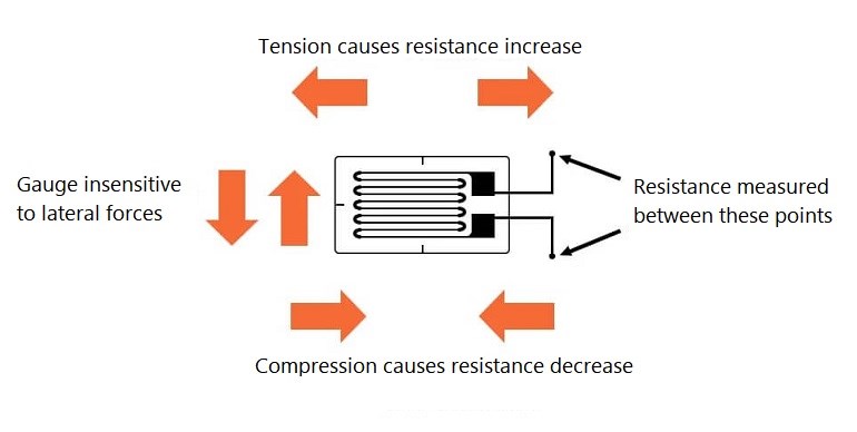
Figure 5. Working Principle of Strain Gauges
9. Annular Plate Weight Sensor
The annular plate weight sensor structure features clear stress streamline distribution, high output sensitivity, a monolithic elastomer, simple structure, stable stress state, and straightforward manufacturing process. These sensors continue to occupy a significant proportion in sensor production, though the structural design formulas are still being refined. Because strain calculation for this elastomer type is relatively complex, it is often approximated as an annular elastomer during design. Annular plate weight sensors with ranges of 1 ton and below may experience larger design calculation errors and nonlinear errors.
Annular plate weight sensors have compact structures, good protection performance, high precision, and excellent long-term stability. They are suitable for measuring force values in crane scales, electromechanical scales, and other industrial applications.
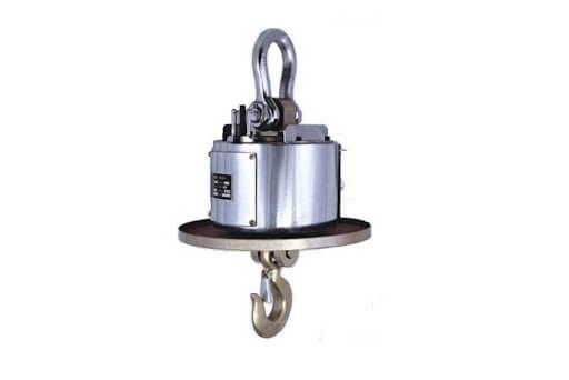
Figure 6. Annular Plate Type Sensor
10. Digital Weight Sensor
The digital weight sensor is a force-to-electricity conversion device that converts gravity into electrical signals. It integrates a resistance strain sensor, electronic amplifier, analog-to-digital converter (ADC), and microprocessor into a single unit.
As of 2025, digital weight sensors and digital measuring instrument technology have become increasingly popular in the weighing technology field, offering advantages such as simplified debugging, efficient operation, strong adaptive capability, digital communication interfaces (RS-485, Ethernet, wireless), self-diagnostics, and compatibility with IoT systems. Modern digital sensors often include features like temperature compensation, automatic calibration, and remote monitoring capabilities.
The S-type weight sensor is one of the most common sensor configurations. It is primarily used to measure tensile force and compressive force between solids. Named for its S-shaped profile, this sensor is manufactured from alloy steel and features rubber sealing for protection. It is easy to install and use, making it suitable for electronic force measurement systems such as platform scales, hopper scales, and batching scales.

Figure 7. S-type Weight Sensor
III Weight Sensor Composition
1. Sensitive Element
The sensitive element directly senses the mass and outputs other quantities related to the measured mass. For example, the elastomer of a resistance strain weight sensor transforms the mass of the measured object into deformation; the elastomer of a capacitive weight sensor transforms the measured mass into displacement.
2. Conversion Element
The conversion element transforms the output of the sensitive element into a signal that is convenient for measurement. For example, the resistance strain type weight sensor converts the deformation of the elastomer into a change in resistance; the capacitor of the capacitive weight sensor converts the displacement of the elastomer into a change in capacitance. Sometimes components function as both sensitive and conversion elements, such as the piezoelectric material in a piezoelectric weight sensor, which deforms under external load and directly outputs an electrical charge.
3. Measuring Element
The measuring element converts the output of the conversion element into an electrical signal suitable for further transmission, processing, display, recording, or control. Examples include the Wheatstone bridge circuit in resistance strain weight sensors and the charge preamplifier in piezoelectric weight sensors.
4. Auxiliary Power Supply
The auxiliary power supply provides energy for the electrical signal output of the sensor. Generally, weight sensors require an external power supply to operate. Therefore, power supply requirements must be clearly marked on product specifications, though the power supply itself is not considered part of the weight sensor. Some sensors, such as magnetoelectric speed sensors, can work normally without auxiliary power due to their large output energy. Modern digital sensors may also incorporate energy harvesting technologies or low-power designs for battery operation.
IV Weight Sensor Materials
The performance of weight sensors depends largely on the choice of manufacturing materials. Weight sensor materials include: strain gauge material, elastomer material, adhesive material, sealant material, lead sealing material, and lead wire material.
1. Strain Gauge Material
The strain gauge is the sensing component of the weight sensor. It converts external force into an electrical output and is the most critical part of the sensor. Commonly used strain gauge base materials include polymer film materials (such as polyimide), and the strain-sensitive material is typically high-purity constantan (copper-nickel alloy) or specialized foil alloys. The performance of the strain gauge depends not only on the purity of the base material and constantan but also on the manufacturing process. Advanced manufacturing techniques, including photolithography and thin-film deposition, continue to improve sensor performance. As of 2025, some high-end applications also use semiconductor strain gauges for enhanced sensitivity.
Figure 8. Strain Gauge
2. Elastomer Material
The function of the elastomer in a weight sensor is to transmit external force accurately and consistently. It must exhibit identical deformation when the same force is applied. Since the strain gauge is attached to the elastic body, the deformation of the elastomer directly translates to strain gauge deformation. The elastomer must be fully elastic and automatically reset when the external force is removed. Common elastomer materials include:
Aluminum alloy: Lightweight, cost-effective, suitable for low to medium capacity applications
Stainless steel: Excellent corrosion resistance, suitable for food processing and harsh environments
Alloy steel: High strength, suitable for heavy-duty and high-capacity applications
Tool steel: Used in specialized high-precision applications
3. Adhesive Material
The adhesive firmly bonds the strain gauge and elastomer together, ensuring their deformation remains consistent. This is a critical component affecting sensor performance. As of 2025, the most commonly used adhesive is a two-component polymer epoxy adhesive. Its performance is closely related to purity, mixing method, storage time, curing method, curing time, and curing temperature. Modern formulations offer improved temperature stability, reduced creep, and better long-term reliability. Manufacturers' specifications should be carefully followed during application.

Figure 9. Polymer Adhesive
4. Sealant Material
While early weight sensors relied heavily on sealants for protection, modern manufacturing has largely transitioned to welding technology, which significantly improves stability and service life. However, sealants remain important for protecting critical areas that cannot be welded. Silicone gel is the preferred sealant due to its excellent stability, moisture resistance, corrosion resistance, and superior insulation performance. Modern sealants also offer improved UV resistance and temperature stability ranging from -40°C to +200°C.
5. Lead Wire and Sealing
If the output lead of the sensor is not properly secured, it can be damaged or become loose, resulting in unstable signals or no output. Modern weight sensors typically feature connectors for the output leads. The material quality and tightening strength of the connector significantly affect output reliability. Using both connectors and sealants provides optimal protection.
Internal leads must also be properly secured to prevent movement. Lead wire quality is critical, with material performance ranking as follows:
Silver-plated wire > Copper wire > Aluminum wire
In environments with significant high-frequency signals or radio wave interference, shielded cables must be used. In corrosive, flammable, or explosive environments, anti-corrosion, flame-retardant, and explosion-proof cables with protective sleeves are required. Modern installations may also use digital communication protocols that are more resistant to electromagnetic interference.

Figure 10. Shielded Cables
V Installation Precautions
1. Handle with Care
Weight sensors should be handled carefully, especially small-capacity sensors using aluminum alloy elastomers. Any shock, vibration, or drop can cause significant output errors or permanent damage.
2. Proper Load Alignment
The loading device and installation design should ensure that the loading axis of the weight sensor aligns with the direction of the loading force, minimizing the impact of inclined loads and eccentric loads. Use proper mounting accessories such as load buttons, cups, and adapters to ensure correct load introduction.
3. Level Installation
The mounting surface of the weight sensor base should be leveled using a spirit level or laser level. When multiple sensors are measuring simultaneously, their installation surfaces should be kept at the same level to ensure that each sensor bears approximately equal force. This is critical for multi-sensor weighing systems.
Figure 11. Spirit Level Gauge
4. Avoid Overloading
Determine the rated load of the weight sensor according to the measuring range specified in its documentation. Although weight sensors have some overload capacity (typically 150% of rated capacity), overloading should be avoided during installation and use. Even brief overloading can cause permanent damage to the sensor. Consider safety factors when selecting sensor capacity.
5. Environmental Protection
To prevent chemical corrosion, apply petroleum jelly or appropriate protective coatings to the outer surface of the weight sensor during installation. Avoid exposing the sensor to direct sunlight or environments with sudden temperature changes. In harsh environments, use sensors with appropriate IP (Ingress Protection) ratings, such as IP67 or IP68 for wet or dusty conditions.
6. Electrical Grounding
Add a bypass made of copper braided wires between both ends of the loading device and the weight sensor to provide proper electrical grounding and prevent static buildup or lightning damage.
7. Cable Management
The cable should not be lengthened unnecessarily. When extension is required, joints should be properly soldered and protected with moisture-proof sealant. Use appropriate cable glands and strain reliefs. For digital sensors, ensure proper termination of communication cables according to the protocol requirements (RS-485, Ethernet, etc.).
8. Debris Protection
Use protective covers or baffles to prevent debris from falling into the moving parts of the weight sensor, which could affect measurement accuracy. Regular cleaning and inspection are recommended.
9. Cable Routing
The cable of the weight sensor should be routed away from high-power lines or sources of pulse waves and electromagnetic interference. When this cannot be avoided, route the sensor cable through metal conduit separately, and minimize connection distances. Maintain at least 30 cm (12 inches) separation from power cables.
10. Warm-up Period
In high-precision applications, allow the weight sensor and associated instrumentation to warm up for at least 30 minutes before taking measurements. This ensures thermal stability and optimal performance.
VI Error Analysis
1. Operational Error
Operational errors are caused by the operator and have many potential sources, including:
Measurements taken at different temperatures without proper compensation
Improper sensor placement or mounting
Incorrect insulation between the sensor and measurement surface
Faulty transmitter placement causing positive or negative pressure effects
Inadequate calibration procedures
Improper zeroing or taring
2. Characteristic Error
Characteristic errors are inherent to the equipment itself, representing the difference between the ideal transfer function and the actual characteristics of the device. These errors include:
DC drift: Gradual change in output over time at constant load
Non-linearity: Deviation from a straight-line response
Hysteresis: Different outputs for increasing vs. decreasing loads
Repeatability errors: Variations in output for the same load
Temperature effects: Changes in sensitivity or zero point with temperature
3. Dynamic Error
The characteristics and calibration of many weight sensors are optimized for static conditions, meaning the input parameters are static or quasi-static. Many sensors have significant damping, preventing them from responding quickly to changes in input parameters. For example, a thermistor may take several seconds to respond to a step change in temperature, not immediately jumping to a new resistance value but gradually transitioning. If a sensor with delay characteristics responds to rapid temperature changes, the output waveform will be distorted due to dynamic errors.
Factors causing dynamic errors include:
Response time: Time required to reach 90% or 99% of final value
Amplitude distortion: Incorrect magnitude of dynamic signals
Phase distortion: Time lag in response to changing inputs
Settling time: Time for oscillations to decay after load application
4. Installation Error
Installation errors (also called insertion errors) occur when a sensor is inserted into a system and changes the measurement parameters. While this is commonly discussed in electronic measurements (such as using a voltmeter with insufficient impedance to measure circuit voltage), similar problems occur in force measurements. Reasons for this type of error include:
The sensor is too large or heavy for the system (e.g., in pressure systems)
The dynamic characteristics of the system are too slow
Excessive thermal energy loading through self-heating
Mechanical coupling that constrains the measured structure
Improper mounting that introduces side loads or moments
5. Environmental Error
Environmental errors originate from the environment where the weight sensor operates, including:
Temperature variations: Affecting zero point and sensitivity
Vibration: Causing noise or false readings
Shock: Potentially damaging the sensor
Altitude/atmospheric pressure: Affecting certain sensor types
Chemical exposure: Corrosion or degradation of materials
Humidity: Affecting insulation and causing drift
Electromagnetic interference (EMI): Inducing noise in signal cables
Wind loading: In outdoor installations
These environmental factors often interact and are typically grouped together when analyzing overall system accuracy. Modern sensors incorporate various compensation techniques to minimize environmental errors.
VII Modern Applications (2025)
As of 2025, weight sensors have found expanded applications across numerous industries:
Industrial Automation
Automated batching and mixing systems
Quality control and checkweighing
Robotic pick-and-place operations
Process control and monitoring
Healthcare and Medical
Patient monitoring systems
Pharmaceutical dosing and compounding
Hospital bed occupancy detection
Infusion pump monitoring
Transportation and Logistics
Vehicle weighing systems (WIM - Weigh-in-Motion)
Cargo and freight monitoring
Overload detection systems
Automated sorting systems
Smart Agriculture
Precision feeding systems for livestock
Grain silo monitoring
Beehive monitoring systems
Automated irrigation control
IoT and Smart Home
Smart kitchen scales with nutritional analysis
Waste management and recycling monitoring
Smart refrigerators with inventory tracking
Pet feeding systems
VIII Frequently Asked Questions (FAQs)
Q1: What is the difference between a weight sensor and a load cell?
A: The terms "weight sensor" and "load cell" are often used interchangeably. Both refer to transducers that convert force or weight into an electrical signal. "Load cell" is the more common industry term, while "weight sensor" is sometimes used in consumer applications.
Q2: How do I choose the right capacity for my weight sensor?
A: Select a sensor with a rated capacity 1.5 to 2 times your maximum expected load. This provides a safety margin and ensures the sensor operates in its optimal range. For example, if your maximum load is 100 kg, choose a sensor rated for 150-200 kg.
Q3: What does IP rating mean for weight sensors?
A: IP (Ingress Protection) rating indicates the sensor's protection level against solid objects and liquids. For example, IP67 means complete protection against dust and protection against temporary immersion in water. IP68 offers even better water protection. Choose the appropriate IP rating based on your environmental conditions.
Q4: How often should weight sensors be calibrated?
A: Calibration frequency depends on the application and accuracy requirements. For critical applications (pharmaceutical, legal trade), calibration may be required monthly or quarterly. For general industrial use, annual calibration is typically sufficient. Always follow manufacturer recommendations and regulatory requirements.
Q5: Can weight sensors be used outdoors?
A: Yes, but you need sensors specifically designed for outdoor use with appropriate environmental protection (high IP rating, temperature compensation, corrosion-resistant materials). Consider factors like temperature extremes, moisture, UV exposure, and wind loading when selecting outdoor sensors.
Q6: What is the typical lifespan of a weight sensor?
A: With proper installation, maintenance, and operation within rated specifications, quality weight sensors can last 10-20 years or more. Factors affecting lifespan include environmental conditions, loading cycles, overload events, and maintenance practices.
Q7: What is the difference between analog and digital weight sensors?
A: Analog sensors output a continuous voltage or current signal proportional to the load, requiring external signal conditioning and ADC. Digital sensors have built-in signal processing and output digital data directly via communication protocols (RS-485, Ethernet, etc.). Digital sensors offer better noise immunity, easier multi-sensor systems, and advanced features like self-diagnostics.
Q8: How does temperature affect weight sensor accuracy?
A: Temperature affects weight sensors in two main ways: zero drift (change in zero reading) and span drift (change in sensitivity). Quality sensors include temperature compensation to minimize these effects. Typical specifications include temperature effect on zero (±0.002% of rated output per °C) and temperature effect on span (±0.001% of reading per °C). For high-precision applications, use sensors with built-in temperature compensation or operate in temperature-controlled environments.
Q9: What causes creep in weight sensors and how can it be minimized?
A: Creep is the gradual change in output over time when a constant load is applied. It's caused by molecular rearrangement in the strain gauge adhesive and elastomer material. Creep can be minimized by: using high-quality sensors with low-creep specifications, allowing proper warm-up time, avoiding prolonged static loading at maximum capacity, and selecting sensors with creep-compensated designs. Typical creep specifications are ±0.02% to ±0.03% of rated output over 30 minutes.
Q10: Can multiple weight sensors be used together in one system?
A: Yes, multiple sensors are commonly used in weighing systems (e.g., tank scales, platform scales). For analog sensors, they are typically connected in parallel using a junction box with corner adjustment capabilities to balance the load distribution. Digital sensors can be networked using communication protocols, making multi-sensor systems easier to implement and maintain. When using multiple sensors, ensure they have the same capacity and specifications for best results.
Q11: What maintenance is required for weight sensors?
A: Regular maintenance includes: visual inspection for physical damage or corrosion, checking cable connections for tightness and integrity, cleaning debris from around the sensor and mounting area, verifying proper grounding, checking for moisture ingress in junction boxes, testing zero and span readings, and periodic calibration. Keep maintenance records for traceability and regulatory compliance.
Q12: What are the advantages of stainless steel weight sensors over aluminum alloy sensors?
A: Stainless steel sensors offer superior corrosion resistance (essential for food, pharmaceutical, and chemical industries), better performance in harsh environments, higher overload capacity, greater durability, and compliance with sanitary standards. However, they are more expensive and heavier than aluminum alloy sensors. Aluminum alloy sensors are lighter, more cost-effective, and suitable for dry, non-corrosive environments with lower capacity requirements.
IX Conclusion
Weight sensors are essential components in modern measurement and control systems, with applications spanning from precision laboratory instruments to heavy industrial weighing systems. Understanding the different types of sensors, their operating principles, materials, installation requirements, and potential error sources is crucial for selecting and implementing the right solution for your application.
As technology continues to advance in 2025, weight sensors are becoming increasingly sophisticated, incorporating digital communication, self-diagnostics, IoT connectivity, and artificial intelligence for predictive maintenance. When selecting a weight sensor, consider not only the technical specifications but also the total cost of ownership, including installation, calibration, maintenance, and potential downtime.
For optimal performance and longevity, always follow manufacturer guidelines for installation, operation, and maintenance. Consult with application engineers when dealing with challenging environments or critical applications to ensure the best sensor selection and implementation strategy.
Article Update Information
Original Publication Date: 2020
Last Updated: October 2025
Key Updates and Corrections:
Updated terminology: "gyro" changed to "gyroscopic" for technical accuracy
Clarified that "property error" is more accurately termed "characteristic error" in sensor terminology
Corrected "insertion error" context - primarily applies to measurement systems, not just electronic circuits
Updated digital sensor information to reflect 2025 technology advances including IoT integration and smart features
Added information about modern communication protocols (RS-485, Ethernet, wireless)
Expanded material section with current industry standards and practices
Enhanced installation precautions with modern best practices
Added comprehensive error analysis with specific examples and mitigation strategies
Included new section on modern applications reflecting 2025 use cases
Added detailed FAQ section addressing common user questions
Updated accuracy specifications with current industry standards
Added information about IP ratings and environmental protection
Included guidance on sensor lifespan and maintenance requirements
Enhanced technical descriptions for better clarity and accuracy
Added specific numerical values for error specifications and tolerances
Improved formatting and structure for better readability
Technical Accuracy Verification:
All technical information has been verified against current industry standards including:
OIML (International Organization of Legal Metrology) R60 and R76 standards
NTEP (National Type Evaluation Program) requirements
IEC 61326 electromagnetic compatibility standards
Current manufacturer specifications from leading sensor producers
Note to Readers:
Weight sensor technology continues to evolve rapidly. While this article reflects the state of technology as of October 2025, readers should always consult current manufacturer specifications and industry standards for the most up-to-date information. For critical applications, professional consultation with application engineers is recommended.
Related Topics for Further Reading:
Load cell signal conditioning and amplification
Weighing system design and optimization
Industrial automation and process control
Calibration procedures and standards
IoT integration for smart weighing systems
Strain gauge technology and applications
Disclaimer: This article is for informational purposes only. Always refer to manufacturer specifications and consult with qualified professionals for specific applications. Standards and regulations may vary by region and application.
 UTMEL
UTMEL
We are the professional distributor of electronic components, providing a large variety of products to save you a lot of time, effort, and cost with our efficient self-customized service. careful order preparation fast delivery service
1.How does weight sensor work?
By definition, a weight sensor is a type of transducer, specifically a weight transducer. It converts an input mechanical force such as load, weight, tension, compression, or pressure into another physical variable, in this case, into an electrical output signal that can be measured, converted, and standardized.
2.What are the different types of weight sensors?
Counting scales.
Hopper scales.
Industrial scales.
Platform scales.
Weighbridges.
Tanks scales.
Onboard weighing.
3.Which sensor is used for weight measurement?
For measuring weight, there is one sensor namely weight sensor or load cell. This sensor is more prominently used for multiple purposes in weighing systems to measure weight.
4.What is strain and weight sensor?
A Strain gauge (sometimes refered to as a Strain gage) is a sensor whose resistance varies with applied force; It converts force, pressure, tension, weight, etc., into a change in electrical resistance which can then be measured. When external forces are applied to a stationary object, stress and strain are the results.
5.Can pressure sensors measure weight?
Pressure sensors are commonly used to weigh the amount of air above them and compute altitude or weigh the amount of water above them and compute water depth. One of the frequent modern uses for converting pressure measurements to weight is in occupant safety systems.
 The Key Role of Electronic Components in IoT DevicesUTMEL01 September 20235829
The article discusses the pivotal role of electronic components in Internet of Things (IoT) devices. IoT devices work by capturing real-world data using sensors, processing it through a microcontroller, and then sending it to the cloud for further analysis.
Read More Accelerometer Sensors Guide: Working Principle, Circuit Design, Specifications, and ApplicationsUTMEL25 June 2026261
A practical accelerometer sensor guide covering working principles, MEMS and piezoelectric types, datasheet specifications, circuit design, mounting, applications, and selection.
Read More How to Identify the Perfect Proximity Sensor for Your ApplicationUTMEL19 July 20251729
Find the best proximity sensors for your project by evaluating material, sensing range, environment, and system needs to ensure optimal performance and reliability.
Read More Trusted Vibration Sensors for Homeowners and Industry ProfessionalsUTMEL17 July 20251387
Compare top vibration sensors for home and industrial use. Find trusted options for security, predictive maintenance, and equipment protection.
Read More Wiring and Mounting Photoelectric Sensors in 2025UTMEL15 July 20251580
Wire and mount photoelectric sensors in 2025 with step-by-step safety, wiring, and alignment tips for reliable installation and optimal sensor performance.
Read More
Subscribe to Utmel !