
 Product
 Brand
Brand Articles
 Tools
Tools
Thermistor: Characteristics, Classification, Symbol and Applications
Basics of NTC and PTC Thermistors
Thermistors are a distinct class of sensitive electronic components. They are divided into Positive Temperature Coefficient (PTC) thermistors and Negative Temperature Coefficient (NTC) thermistors based on their response to temperature changes. The defining characteristic of a thermistor is its high sensitivity to heat, exhibiting different resistance values at different temperatures. PTC thermistors exhibit increased resistance as temperature rises, whereas NTC thermistors show decreased resistance as temperature rises. Both types fall under the category of passive semiconductor devices.
Catalog
I. Main characteristics
1. High sensitivity: Its resistance temperature coefficient is 10 to 100 times greater than that of metal (like platinum RTDs), and it can detect temperature changes as small as 10-6 °C.
2. Wide operating temperature range: Normal temperature devices are typically suitable for -55°C ~ 315°C. High-temperature devices can operate above 315°C (specialized ceramics can reach up to 1000°C, though standard models rarely exceed 500°C). Low-temperature devices are suitable for cryogenic applications from -273°C ~ -55°C.
3. Small volume: Due to their miniature size (often SMD or small bead), they can measure the temperature of voids, cavities, and biological vessels that cannot be measured by bulkier thermometers.
4. Flexibility: The nominal resistance value can be arbitrarily selected between 0.1Ω and 100kΩ.
5. Manufacturability: Easy to be processed into complex shapes and can be produced in large quantities, making them cost-effective.
6. Good stability and strong overload capacity. However, care must be taken regarding the "self-heating" effect, where the current used to measure the thermistor heats the component itself.
II. Classification
1. PTC Thermistors
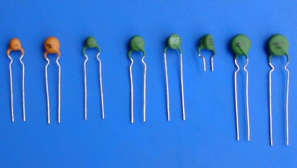
PTC Thermistors
PTC (Positive Temperature Coefficient) Thermistor refers to a thermistor that exhibits a sharp increase in resistance at a specific critical temperature (Curie point). It can be used as a constant temperature heater or a sensor. The material is typically a sintered body with Barium Titanate (BaTiO3), Strontium Titanate (SrTiO3), or Lead Titanate (PbTiO3) as the main component. Small amounts of dopants such as Nb, Ta, Bi, Sb, Y, and La are added to control the atomic valence and make it semiconductive. This semiconducting ceramic is formed by general ceramic technology. High-temperature sintering transforms the barium titanate and its solid solution into a semiconductive state. Its temperature coefficient and Curie point temperature vary with the composition and sintering conditions (especially the cooling rate).
Barium titanate crystals belong to a perovskite structure and are a ferroelectric material. Pure barium titanate is an insulator. However, by adding trace rare earth elements, the resistivity increases sharply by several orders of magnitude near the Curie temperature, resulting in the PTC effect. This phenomenon is related to the ferroelectricity of the BaTiO3 crystal. Barium titanate semiconductive ceramic is a polycrystalline material with intergranular interfaces (grain boundaries). When the ceramic reaches a certain temperature (Curie point), the potential barrier at the grain boundary increases, making it difficult for electrons to cross, which causes the resistance to rise sharply.
Experiments show that within the operating temperature range, the resistance-temperature characteristics of PTC thermistors can be approximated by the following formula:
RT = RT0 × exp[Bp(T-T0)]
In the formula, RT and RT0 represent the resistance value when the temperature is T and T0, and Bp is the material constant.
Modern Applications: PTC thermistors are now critical in the electric vehicle (EV) industry for battery heating systems and cabin heaters. They act as "thermal switches." When current passes through the element, the temperature rises. If the temperature exceeds the Curie point, the resistance increases drastically, limiting the current. This self-regulating property prevents overheating, making them ideal for electric irons, drying cabinets, and overcurrent protection (resettable fuses) in circuits.
2. NTC Thermistors
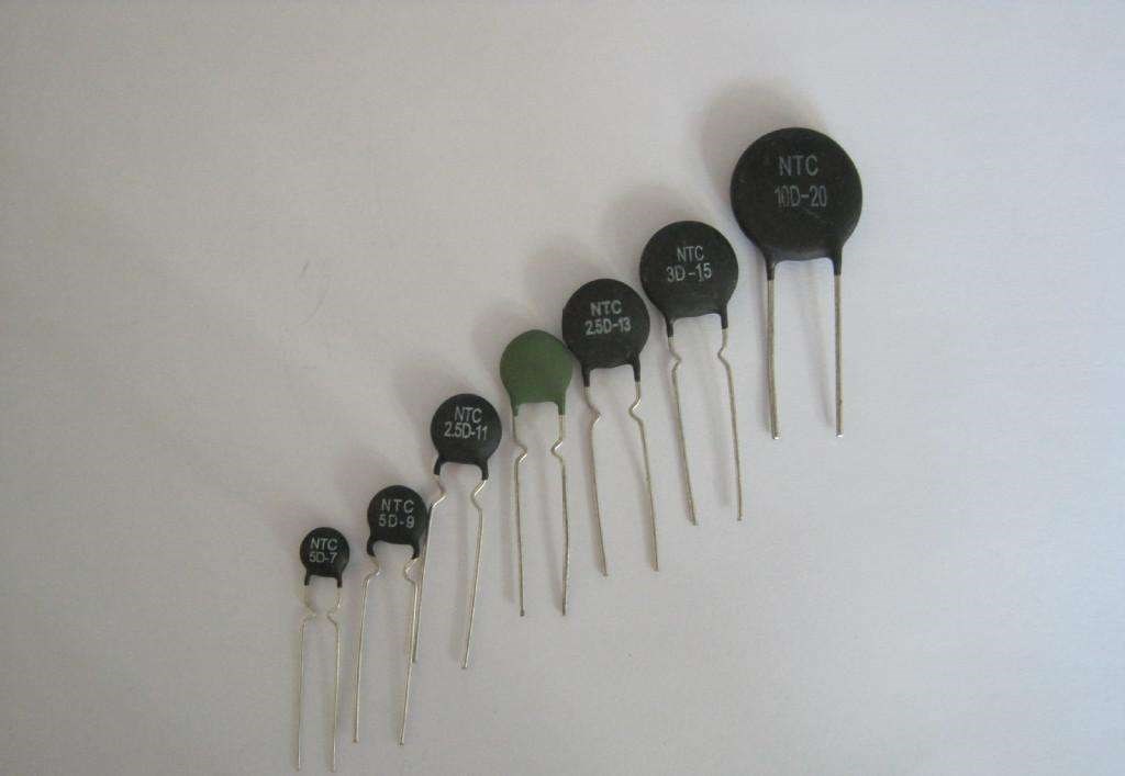
NTC Thermistors
NTC (Negative Temperature Coefficient) Thermistor refers to a thermistor where resistance decreases exponentially as temperature rises. The material is typically a semiconductive ceramic made from a mixture of two or more metal oxides such as manganese, copper, silicon, cobalt, iron, nickel, and zinc. These are formed and sintered to create a reliable semiconductor. Its resistivity and material constant vary based on the composition ratio, sintering atmosphere, and structural state.
Most NTC ceramics have a spinel structure. The resistance value can be calculated using the Arrhenius equation approximation:
Rt = R0 × exp[B(1/T - 1/T0)]
Where Rt is the resistance at temperature T (in Kelvin), R0 is the nominal resistance at reference temperature T0 (usually 25°C, or 298.15K), and B (Beta) is the material constant.
Types:
Power NTCs: Used for inrush current limiting in power supplies (SMPS). They have high resistance at startup (cold) to stop current spikes, then heat up and drop resistance to improve efficiency.
Sensing NTCs: High precision components used for temperature measurement.
The accuracy of modern NTC thermistor thermometers can reach 0.05 °C, and the response time can be less than 10s. They are essential in 3D printer hot-ends, medical thermometers, smart home thermostats, and battery management systems (BMS).
3. CTR
The Critical Temperature Resistor (CTR) has a sudden, drastic change in negative resistance. At a specific critical temperature, the resistance value decreases sharply with increasing temperature. The constituent material is a mixed sintered body of element oxides such as vanadium, barium, strontium, and phosphorus. It is often referred to as a "glass thermistor" due to its semi-glassy semiconductor nature. The sudden change in resistance is caused by a semiconductor-metal phase shift in the material structure (e.g., Vanadium Dioxide phase transition). CTRs are less common than standard NTC/PTC but are used in specific temperature control alarms and thermal switching applications.
III. Thermistor symbol
In circuit diagrams, knowing the correct symbol is vital. The resistance of the thermistor changes with the ambient temperature.
Text Symbol: Usually "RT", "TH", or simply "R".
Graphical Symbol: Based on the standard (IEC vs. ANSI), it may look like a rectangular box or a zig-zag resistor line with a diagonal line through it. The diagonal line often has a "hockey stick" end.
Notation: The symbol often includes "t°" to indicate temperature sensitivity.
Note: Do not confuse them with Varistors (often labeled "RV" or "MOV") which look similar but are voltage-dependent, not temperature-dependent.

Comparison: Symbol of Photoresistor (left) vs. Thermistor (right)
Representation of thermistor in the circuit diagram:

The thermistor in a circuit diagram context
IV. Thermistor Test
Testing a thermistor is straightforward using a digital multimeter. Set the multimeter to the Ohm (resistance) range appropriate for the thermistor's nominal value (usually 20k or 200k range).
Step 1: Room Temperature Test
Measure the resistance at room temperature (approx. 25°C). The value should be close to the nominal value marked on the component (e.g., a "10K NTC" should read close to 10kΩ). A deviation of ±2% to ±5% is normal depending on tolerance. If it reads infinite (open circuit) or zero (short circuit), the component is damaged.
Step 2: Temperature Response Test
While connected to the multimeter, bring a heat source (like a warm soldering iron or even a hair dryer) close to the thermistor without touching it directly.
For NTC: The resistance should drop smoothly.
For PTC: The resistance should rise.
Crucial Testing Precautions:
Body Heat: Do not pinch the thermistor body with your fingers during measurement. Your body heat (37°C) is significantly higher than room temperature (25°C) and will cause a measurement error, making a 10k thermistor read closer to 6k or 7k.
Self-Heating: Ensure the multimeter current does not heat the component.
Physical Safety: Do not touch the hot soldering iron to the component plastic or epoxy coating.
V. Applications
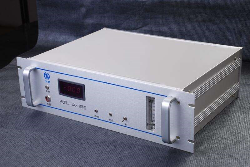
Thermistors are used inside gas analyzers and flow meters
Thermistors are ubiquitous in modern electronics. Their applications leverage three main characteristics: resistance-temperature relationship, self-heating effects, and thermal inertia.
Battery Management Systems (BMS): This is the most critical modern application. In Electric Vehicles (EVs) and energy storage, NTC thermistors monitor the temperature of individual battery cells to prevent thermal runaway and ensure safe charging.
Inrush Current Limiting: Power NTCs are placed in series with the input of power supplies (SMPS). When you plug in a device, the NTC is cold (high resistance), limiting the initial surge of current. It then heats up, dropping resistance to allow normal operation.
3D Printing: Glass-bead NTC thermistors (typically 100kΩ) are used to monitor the temperature of the hot-end nozzle and the heated print bed with high precision.
Medical Devices: Used in electronic thermometers, incubators, and respiratory equipment due to their high sensitivity and fast response time.
Circuit Protection: PTC thermistors act as "Resettable Fuses" (PolySwitch). If a fault causes high current, the PTC heats up, trips to high resistance, and cuts the circuit. Once the fault is removed and the device cools, it resets automatically.
Compensation: Used to compensate for the temperature drift of other components (like copper coils or oscillators) in precision circuits.
Article Recommended:
 UTMEL
UTMEL
We are the professional distributor of electronic components, providing a large variety of products to save you a lot of time, effort, and cost with our efficient self-customized service. careful order preparation fast delivery service
How are thermistors classified?
According to the resistance temperature coefficient, it can be divided in two categories: positive temperature coefficient thermistor (PTC) and negative temperature coefficient thermistor (NTC); In terms of the resistance changes with temperature, there are slow variant (linear) and mutant (nonlinear).
What is thermistor and its application?
Thermistors are used as temperature sensors. They can be found in every day appliances such as fire alarms, ovens and refrigerators. They are also used in digital thermometers and in many automotive applications to measure temperature.
What are different types of thermistor and what are their applications Class 11?
The main two types of thermistors are NTC (Negative Temperature Coefficient) and PTC (Positive temperature coefficient). Thermistors measure temperature by using resistance. With an NTC thermistor, as the temperature increases the resistance decreases, and when the temperature decreases, the resistance increases.
What is the working principle of thermistor?
The working principle of a thermistor is that its resistance is dependent on its temperature. We can measure the resistance of a thermistor using an ohmmeter.
Is a thermistor a transducer?
The Thermistor is a solid-state temperature sensing device that acts a bit like an electrical resistor but is temperature-sensitive. Thermistors can be used to produce an analog output voltage with variations in ambient temperature and as such can be referred to as a transducer.
 What are the Differences Between Pull up and Pull down Resistors?UTMEL22 October 202539134
Pull up is to clamp an uncertain signal to a high level with a resistor, and the resistor also acts as a current limiter. In the same way, pull down means to clamp the uncertain signal to a low level through a resistor. To pull up is to input current to the device, and the pull-down is to output the current.
Read More Rheostat Basics: Types, Principle and FunctionsUTMEL25 December 202518782
A rheostat is a device that can adjust the size of the resistance and can be connected to the circuit to adjust the size of the current. A general rheostat is composed of a wire with a larger resistance and a device that can change the contact point to adjust the effective length of the resistance wire. Rheostat can limit the current and protect the circuit, and change the voltage distribution in the circuit.
Read More Basic Introduction to Metal Film ResistorUTMEL28 August 202014035
Metal film resistors are a kind of film resistors. Metal film resistors are resistors in which special metals or alloys are used as resistor materials, and the resistor film layer is basically formed on ceramic or glass by vacuum evaporation or sputtering.
Read More Varistor: Definition, Function, Working and TestingUTMEL03 April 202584411
A varistor is a device with a non-linear volt-ampere characteristic. When the voltage applied to the varistor is lower than its threshold value, the current flowing through it is extremely small, which is equivalent to a resistor with infinite resistance, vice versa. The most common varistor is a metal oxide varistor (MOV).
Read More Photoresistor Basics: Types, Principles and ApplicationsUTMEL16 October 202546992
The article introduces the photoresistor’s main characteristics and principles including the working principle and structural principle. There are three types of photoresistor: ultraviolet photoresistors, infrared photoresistors, visible light photoresistors. Dimming circuit and light switch are the two applications of the photoresistor.
Read More
Subscribe to Utmel !
![AFE8220TPZPQ1]() AFE8220TPZPQ1
AFE8220TPZPQ1Texas Instruments
![HMC921LP4E]() HMC921LP4E
HMC921LP4EAnalog Devices Inc.
![HMC392ALC4]() HMC392ALC4
HMC392ALC4Analog Devices Inc.
![LTC5509ESC6#TRMPBF]() LTC5509ESC6#TRMPBF
LTC5509ESC6#TRMPBFLinear Technology/Analog Devices
![F1240NBGI]() F1240NBGI
F1240NBGIRenesas Electronics America Inc.
![ADL5591ACPZ-R7]() ADL5591ACPZ-R7
ADL5591ACPZ-R7Analog Devices Inc.
![HMC611LP4ETR]() HMC611LP4ETR
HMC611LP4ETRAnalog Devices Inc.
![ERA-33SM]() ERA-33SM
ERA-33SMMini-Circuits
![MMG3007NT1]() MMG3007NT1
MMG3007NT1NXP USA Inc.
![HMC733LC4BTR]() HMC733LC4BTR
HMC733LC4BTRAnalog Devices Inc.


