
 Product
 Brand
Brand Articles
 Tools
Tools
Solid State Relay Basics: Working, Features and Structure
What is a Solid State Relay?
Catalog
| |
Ⅰ Introduction
The solid state relay is a new type of non-contact switching device composed of solid-state electronic components. It uses the switching characteristics of electronic components (such as switching transistors, triacs, and other semiconductor devices), which can achieve the purpose of making and breaking the circuit without contact and spark, so it is also called "non-contact switch". A solid state relay is a four-terminal active device, two of which are input control terminals, and the other two terminals are output controlled terminals. It has both amplifying and driving functions and isolation functions, which are very suitable for driving high-power switching actuators. Compared with electromagnetic relays, it has higher reliability, no contact, long life, fast speed, and less interference to the outside world. It has been widely used.
Ⅱ Working Principle
SSR can be divided into AC type and DC type according to the occasion of use. They are used as load switches on the AC or DC power supply, and cannot be mixed. The following takes an AC SSR as an example to illustrate its working principle. Figure 1 is a block diagram of its working principle. The components ①~④ in Figure 1 constitute the main body of the AC SSR. On the whole, the SSR has only two input terminals ( A and B) and two output terminals (C and D), it is a four-terminal device.
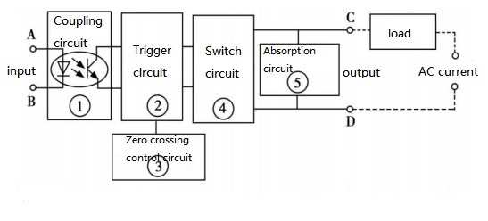
Figure 1. block diagram of working principle of SSR
When working, as long as a certain control signal is added to A and B, the "on" and "off" between the two ends of C and D can be controlled, and the function of "switch" can be realized. The function of the coupling circuit is to provide a channel between the input/output terminals for the input control signal from the A and B terminals, but electrically disconnects the (electrical) connection between the input terminal and the output terminal in the SSR to prevent the output terminal from affecting the input terminal. The component used in the coupling circuit is an "optical coupler", which is sensitive, has a high response speed, and has high insulation (withstand voltage) level between the input and output terminals. Since the load on the input terminal is a light-emitting diode, this makes the input terminal of the SSR easy to match the input signal level and can be directly connected to the computer output interface when in use, which is controlled by the logic level of "1" and "0".
The function of the trigger circuit is to generate a trigger signal that meets the requirements to drive the switch circuit ④ to work, but because the switch circuit does not add a special control circuit, it will generate radio frequency interference and pollute the power grid with high harmonics or spikes. Therefore, the "Zero Crossing Control Circuit" was designed. The so-called "zero crossing" means that when the control signal is added and the AC voltage crosses zero, the SSR is in the on state; and when the control signal is disconnected, the SSR waits for the intersection of the positive half cycle and the negative half cycle of the alternating current, SSR is off state. This design can prevent high-order harmonic interference and pollution to the power grid. The absorption circuit is designed to prevent the impact and interference (or even malfunction) of the switching device triac from the spikes and surges (voltage) from the power supply. Generally, the "RC" series absorption circuit or non- Linear resistance (varistor) are used.
Ⅲ Features
The solid state relay is a non-contact electronic switch with isolation function. There are no mechanical contact parts during the switching process. Therefore, in addition to the same functions as electromagnetic relays, solid state relays also have logic circuit compatibility, vibration resistance and mechanical shock resistance, unlimited installation positions, good moisture, mildew, and corrosion resistance, and excellent performance in explosion protection and prevention of ozone pollution. It has characteristics of low input power, high sensitivity, low control power, good electromagnetic compatibility, low noise, and high operating frequency.
(1) There are no mechanical parts inside the SSR, and the structure adopts a fully-sealed perfusion method. Therefore, the SSR has the advantages of vibration resistance, corrosion resistance, long life, and high reliability, and its switching life is up to 10.1 million times;
(2) Low noise: AC SSR adopts zero-crossing trigger technology, so the voltage rise rate dv/dt and current rise rate di/dt value are effectively reduced on the line, so that the SSR has minimal interference to the mains during long-term operation ;
(3) The switching time is short, about 10ms, which can be used in higher frequency occasions;
(4) Photoelectric isolation is used between the input circuit and the output circuit, and the insulation voltage is above 2500V;
(5) The input power consumption is very low, compatible with TTL and COMS circuits;
(6) There is a protection circuit at the output;
(7) Strong load capacity.
1 Advantage
(1) Long life and high reliability: The solid state relay has no mechanical parts, and the contact function is completed by solid devices. Since there are no moving parts, it can work under high-impact and vibration environments. Because of the components that make up the solid state relay, the inherent characteristics of solid state relays determine the long life and high reliability of solid state relays.
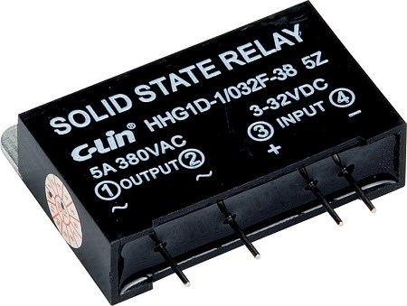
Figure 2. solid state relay
(2) High sensitivity, low control power, and good electromagnetic compatibility: The solid state relay has a wide input voltage range and low drive power, and is compatible with most logic integrated circuits without the need for buffers or drivers.
(3) Fast switching: Because solid-state relays use solid-state devices, the switching speed can range from a few milliseconds to a few microseconds.
(4) Small electromagnetic interference: The solid state relay has no input "coil", no arc ignition and rebound, thus reducing electromagnetic interference. Most AC output solid state relays are a zero-voltage switch, which is turned on at zero voltage and turned off at zero current, reducing the sudden interruption of the current waveform, thereby reducing the switching transient effect.
2 Disadvantage
(1) The voltage drop of the tube after it is turned on is large, the forward voltage drop of the thyristor or triac can reach 1~2V, and the saturation voltage drop of the high-power transistor is also between 1~2V, and the general power field effect tube’s on-resistance is also greater than the contact resistance of mechanical contacts.
(2) The semiconductor device can still have a leakage current of several microamperes to several milliamperes after it is turned off, so ideal electrical isolation cannot be achieved.
(3) Due to the large pressure drop of the tube, the power consumption and heat generation after the conduction is also large, the volume of the high-power solid-state relay is much larger than the electromagnetic relay of the same capacity, and the cost is also higher.
(4) The temperature characteristics of electronic components and electronic circuits have poor anti-interference ability and radiation resistance is also poor. If effective measures are not taken, the work reliability is low.
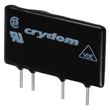
Figure 3. solid state relay 2
(5) Solid state relays are more sensitive to overload and must be protected against overload with a fast fuse or RC damping circuit. The load of the solid state relay is obviously related to the ambient temperature. As the temperature rises, the load capacity will drop rapidly.
(6) The main shortcomings are the on-state voltage drop (corresponding heat dissipation measures are required), off-state leakage current, AC and DC cannot be used universally, the number of contact groups is small.
Ⅳ Structure
The solid state relay is composed of three parts: input circuit, isolation (coupling), and output circuit.
1 Input circuit
According to different types of input voltage, the input circuit can be divided into three types: DC input circuit, AC input circuit, and AC/DC input circuit. Some input control circuits are also compatible with TTL/CMOS, positive and negative logic control, and inversion functions, and can be easily connected with TTL and MOS logic circuits.
For a control signal with a fixed control voltage, a resistive input circuit is used. The control current is guaranteed to be greater than 5mA. For the control signal with a large variation range (such as 3~32V), a constant current circuit is used to ensure reliable operation of the current greater than 5mA within the entire voltage variation range.
2 Isolation coupling
The input and output circuits of solid state relays can be isolated and coupled in two ways: photoelectric coupling and transformer coupling: photoelectric coupling usually uses photodiode-phototransistor, photodiode-bidirectional light-controlled thyristor, photovoltaic cell to realize control side and load side Isolation control; high-frequency transformer coupling uses the self-excited high-frequency signal generated by the input control signal to be coupled to the secondary, detected and rectified, and processed by the logic circuit to form a drive signal.
3 Output circuit
The power switch of the SSR is directly connected to the power supply and the load side to realize the on-off switch of the load power supply. Mainly use high-power transistors, one-way thyristor (Thyristor or SCR), bidirectional thyristor (Triac), power field effect transistor (MOSFET), insulated gate bipolar transistor (IGBT). The output circuit of solid state relay can also be divided into DC output circuit, AC output circuit, and AC/DC output circuit. According to the load type, it can be divided into DC solid state relay and AC solid state relay. Bipolar devices or power FETs can be used for DC output, and two thyristors or one bidirectional thyristor are usually used for AC output. The AC solid-state relay can be divided into single-phase AC solid-state relay and three-phase AC solid-state relay. AC solid-state relays can be divided into random AC solid-state relays and zero-crossing AC solid-state relays according to the timing of turn-on and turn-off.
 UTMEL
UTMEL
We are the professional distributor of electronic components, providing a large variety of products to save you a lot of time, effort, and cost with our efficient self-customized service. careful order preparation fast delivery service
1Which occasions can solid state relays be used?
Solid state relays have been widely used in computer peripheral interface devices, electric furnace heating constant temperature systems, CNC machinery, remote control systems, industrial automation devices; signal lights, flashers, lighting stage lighting control systems; instrumentation, medical equipment, photocopiers, automatic washing machines; automatic Fire-fighting, security systems, as well as switching switches of power capacitors used as power factor compensation for power grids, etc.. They are also widely used in chemical, coal and other occasions that require explosion-proof, moisture-proof, and corrosion-proof.
2 What types of solid state relays can be divided into?
AC solid state relays are divided into voltage zero-crossing conduction type (referred to as zero-crossing type) and random conduction type (referred to as random type) according to the switching mode. According to the output switching element, there are two-way triac output type (ordinary type) and one-way thyristor anti-parallel type (enhanced type). According to the installation method, it is divided into the pin type used on the printed circuit board (natural cooling, no radiator) and the device type fixed on the metal base plate (cooled by the radiator); In addition, the input terminal has a wide range input (DC3-32V) constant current source type and series resistance current limiting type.
3 The difference between zero-crossing SSR and random SSR
When a valid control signal is applied to the input, the output of the random SSR is turned on immediately (speed is in the order of microseconds), while the zero-crossing SSR will not turn on until the load voltage crosses the zero area (about ±15V). When the input terminal cancels the control signal, both the zero-crossing and random SSRs are turned off when the current is less than the sustaining current. Although the zero-crossing SSR may cause the maximum half-cycle delay, it reduces the impact on the load and the generated radio frequency interference, and becomes an ideal switching device. It is most widely used in "single pole single throw" switching occasions. The characteristic of random SSR is fast response speed. It can control the phase shift trigger pulse to easily change the AC grid voltage, so it can be used for precise temperature adjustment, light adjustment and other resistive loads and some inductive loads. The zero-crossing SSR is used as a "switch" (from the "switch" switching function, it is equivalent to an ordinary relay or contactor). Most of the solid state relays we usually talk about are zero-crossing (zero-crossing SSR can only " "Switch" but cannot "regulate voltage"). The random type SSR is mainly used for "chopping wave voltage regulation" (but the control signal of the random type SSR must be a square wave signal that is synchronized with the grid and the rising edge can be changed within the range of 0°-180° to achieve voltage regulation. Signals or 0-5V analog signals cannot adjust the voltage. From the perspective of the "voltage regulation" function, the random SSR is completely different from ordinary relays or contactors). It must be emphasized that all kinds of voltage regulating modules or solid-state relays are used as output contacts within the thyristor, and all rely on changing the conduction angle of the thyristor to achieve the purpose of "voltage regulation", so the waveforms of the output voltage are all sine waves with "missing angles" (different from the complete sine waves output by the auto-voltage regulator), so there are high-order harmonics, a certain amount of noise, and a certain degree of "pollution" in the power grid.
4 Do solid state relays (or other power modules) need to be equipped with radiators?
Yes. Except for single-phase solid state relays with current less than 6A, all power modules need to be used with a suitable radiator.
5 The heating of solid state relay and the choice of radiator
The calorific value of a solid state relay or module is mainly related to the actual current of the load being driven, and has little to do with its own current level. Calculation formula of calorific value (two kinds): 1: Single-phase solid state relay, single-phase AC voltage regulating module, R series solid state voltage regulator Calorific value = actual load current (ampere) × 1.5 watts / ampere For three-phase solid state relays and three-phase AC voltage regulating modules, the actual load current should be the sum of the three-phase actual load currents. 2: For single-phase fully controlled rectifier module Calorific value = actual load current (ampere) x 3.0 watts/ampere. The role of the radiator is to dissipate the heat generated by the solid state relay or module. The heat dissipation effect is not only related to the size of the radiator, but also to the ambient temperature (season), ventilation conditions (natural cooling or forced cooling and air volume) and installation density, etc. The factors are all related. The reference standard for heat dissipation effect: the temperature of the bottom plate (contact surface with the radiator) of the solid state relay or module should not exceed 80°C. Therefore, in actual applications, a 75℃ temperature switch (with a pair of normally closed contacts) can be installed on the radiator mounting surface near the edge of the solid state relay or module (within 20mm) to string the control signal of the solid state relay or module into this pair of normally closed contacts, so that when the temperature of the detection point exceeds 75°C, the normally closed contact trips, cuts off the control signal, and forcibly closes the output of the solid state relay or module to protect it. Generally, where the actual current per phase exceeds 50A, the installation density is high, and the ambient temperature is high, it is best to use a temperature switch for protection. In addition to considering the above factors when selecting a radiator, it is also necessary to consider whether the volume of the solid state relay or the module itself can match the radiator, and the installation space of the radiator in the cabinet. But in the end, it is necessary to ensure that the bottom plate temperature of the solid state relay or module does not exceed 80°C even under the worst conditions.
 What is Time Delay Relay?UTMEL18 December 202516148
Hello everyone, I am Rose. Today I will introduce Time Relay to you. A Time Relay is an electrical component that is used on a circuit with a lower voltage or lower current to turn on or off a circuit with a higher voltage and bigger current or to regulate a higher voltage or larger power. This article will introduce some basic knowledge of Time Relay.
Read More What is Safety Relay?UTMEL12 April 202525632
Safety relays represent a critical advancement in industrial automation technology, serving as essential components in machine safety systems. Unlike standard relays, safety relays are specifically engineered to provide reliable protection in potentially hazardous environments. This article explores the fundamental aspects of safety relays, including their operational principles, wiring configurations, and proper implementation methods in industrial settings.
Read More What is Relay?UTMEL15 November 20217634
Hello everyone, I am Rose. Welcome back to the new post today. Relay is an autonomous electrical appliance used in electric drive systems for control, protection, and signal conversion. It is suitable for remote connection and disconnection of AC and DC small-capacity control circuits.
Read More AC Contactor: What is Self-Locking?UTMEL01 March 202212302
AC contactors often use three arc extinguishing methods: double-break electric arc extinguishing, longitudinal seam arc extinguishing and grid arc extinguishing. It is used to eliminate the arc generated by the moving and static contacts during the opening and closing process.This article mainly introduce the principle of AC Contactor self-locking.
Read More Weak Current Control Strong Current: How to use the Relay?UTMEL28 November 20226483
Hello everyone, I am Rose. Welcome to the new post today. Today I will introduce relay to you. Including its definition, parameters, working principle and so on.
Read More
Subscribe to Utmel !
![CRCW060360K4FKEA]() CRCW060360K4FKEA
CRCW060360K4FKEAVishay Dale
![WSK25121L000FEA]() WSK25121L000FEA
WSK25121L000FEAVishay Dale
![CRCW04025K11FKED]() CRCW04025K11FKED
CRCW04025K11FKEDVishay Dale
![RC0402FR-07160RL]() RC0402FR-07160RL
RC0402FR-07160RLYageo
![WSL0805R0300FEA18]() WSL0805R0300FEA18
WSL0805R0300FEA18Vishay Dale
![RC0805FR-072K21L]() RC0805FR-072K21L
RC0805FR-072K21LYageo
![RC0402FR-071K6L]() RC0402FR-071K6L
RC0402FR-071K6LYageo
![CRCW04024R70FKED]() CRCW04024R70FKED
CRCW04024R70FKEDVishay Dale
![RK73H1JTTD5231F]() RK73H1JTTD5231F
RK73H1JTTD5231FKOA Speer Electronics, Inc.
![MCR01MZPJ101]() MCR01MZPJ101
MCR01MZPJ101ROHM Semiconductor


