Product
 Brand
Brand Articles
 Tools
Tools
What is an Electrical Connector?
Electrical Connectors and WireTerminals
Catalog
I What is an Electrical Connector?
Electrical Connector is an electromechanical component used to join electrical circuits as an interface using a mechanical assembly. It is primarily composed of a female contact (often called the socket or receptacle), and a male contact (often called the plug or pin). Connectors can be broadly categorized by shape into circular and rectangular types, which can be further subdivided based on their termination and locking methods.
To select a suitable electrical connector, one must carefully consider parameters including electrical properties (voltage, current, impedance), safety, mechanical durability, and environmental resilience. As technology evolves, electrical connectors are advancing towards higher speeds, higher density, and greater reliability for extreme environments.
II Electrical Connector Types
1. Circular Electrical Connector
Circular connectors are widely used in industrial, aerospace, and military applications due to their robustness. According to the connection method and the locking mechanism, circular connectors mainly include bayonet, threaded, automatic locking (push-pull), and simple push-pull types.
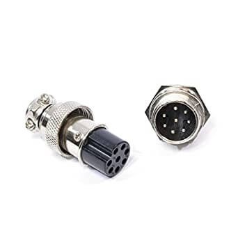
Figure 1. Circular Electrical Connectors
(1) Threaded Connection
This method uses the self-locking feature of screw threads to connect the plug and socket (e.g., M12 connectors or MIL-DTL-5015). For faster connections, some utilize triple-start threads (like MIL-DTL-38999 Series III). To prevent loosening under vibration and shock, a ratchet mechanism or anti-decoupling structure is often integrated.
This structure is reliable, easy to manufacture, and provides excellent resistance to mechanical stress.
(2) Bayonet Connection
This structure typically features three pins spaced 120° apart on the outer periphery of the socket. The matching plug coupling ring is equipped with curved grooves and a loaded spring to ensure rapid, audible, and tactile locking.
It is faster than threaded connections (usually 1/3 turn to mate) and is highly reliable against vibration.
(3) Push-pull Connection
This structure often uses a ball-locking mechanism. Steel balls on the plug engage with an arc groove on the socket. The sleeve locks the balls in place when inserted. To disconnect, the outer sleeve is pulled back to release the lock. This allows for very dense mounting and quick operation, common in medical and audio equipment.
2. Rectangular Electrical Connector
Rectangular connectors are optimized for high-density pin arrangements and space efficiency. Common examples include D-Sub, USB, and heavy-duty rack connectors.

Figure 2. Rectangular Electrical Connector
(1) Straight Plug and Pull Type
This structure relies on the guide mechanism of the plug and socket for alignment. The locking force is often provided by external chassis structures or friction. It is widely used in board-to-board connections, rack-and-panel systems, and blind-mating applications.
(2) Thread-Locking Type
This structure uses screw locks (jackscrews) to secure the connection, ensuring mating integrity. This is standard for D-Sub connectors used in computing and industrial communications, preventing accidental disconnection.
III Structure of Electrical Connector
The electrical connector is composed of a fixed female contact (socket/receptacle), and a free male contact (plug). The socket is often mounted to a panel or PCB, while the plug is attached to a cable.
The electrical connector consists of three basic units: the shell (housing), the insulator, and the contact body.
1. Shell
The shell (or housing) includes the main body, the coupling nut, and the backshell/tail attachment. It mechanically protects the internal insulator and contacts from physical damage. Keyways in the shell ensure polarization (preventing mismatching), while the backshell provides strain relief and cable support.
The shell is also critical for Electromagnetic Interference (EMI) shielding. Materials include aluminum alloy (lightweight), stainless steel (high durability), and composite materials (for weight reduction in aerospace).
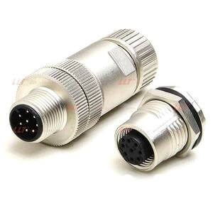
Figure 3. Aluminum Alloy Electrical Connector
2. Insulator
The insulator supports the contacts, keeping them in the correct position and electrically isolating them from each other and the shell. It also includes sealing components (interface seals and wire seals) to provide environmental protection.
Materials must offer high electrical resistance, temperature stability, and flame retardancy. Common materials include thermoset plastics (like Diallyl Phthalate) and high-performance thermoplastics like PEEK or LCP (Liquid Crystal Polymer). Seals are typically molded from silicone rubber.
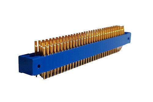
Figure 4. Thermoset Plastic Moulding
3. Contact Body
The contact body allows the flow of electricity and includes the male contact (pin) and female contact (socket). Termination methods include welding/soldering, crimping, press-fit, and IDC.
Contacts are the heart of the connector. They are machined or stamped from elastic copper alloys (like brass, phosphor bronze, or beryllium copper) to ensure conductivity and spring memory. Surfaces are plated with gold (for reliability), silver (for high power), or tin (for cost-effectiveness) to minimize contact resistance and corrosion.
Key structural features often include:
Environmental sealing (IP67/IP68 ratings).
Bayonet or threaded coupling for secure mating.
Multi-keyway polarization to avoid misinsertion.
Crimping for high-vibration resistance.
A shielding ring or spring fingers are often used to ensure 360° electromagnetic interference (EMI) shielding.
IV Electrical Connector Parameters
1. Electrical Parameters
(1) Rated Voltage
Rated voltage (working voltage) depends on the insulating material and the spacing between contacts. It represents the maximum recommended continuous voltage. Users must select a rated voltage higher than their system's operating voltage, considering safety margins and environmental factors like altitude (which lowers breakdown voltage).
(2) Rated Current and Derating
Connectors are rated for a specific current at which they operate normally. However, current flow generates heat due to contact resistance.
The limiting factor is temperature rise. Excessive heat can degrade insulation and soften contacts. Therefore, for multi-core connectors, the current must be derated because clustered contacts heat each other up. The more cores, the lower the allowable current per core. See Table 1 for typical derating values.
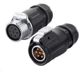
Figure 5. Multi-Core Electrical Connection
Number of Cores | 1 | 2 | 3 | 4 | 5 | 6 | 7 | 8 | 9 | 10 | 11 | 12 | 13 | 14 | >15 |
Derating Rate (%) | 100 | 94.3 | 88.6 | 82.9 | 77.1 | 71.4 | 65.7 | 60 | 54.3 | 48.6 | 42.9 | 37.1 | 31.4 | 25.7 | 20 |
Table 1. Current Derating based on Core Count
(3) Contact Resistance
Contact resistance is the total resistance across the mating pair. It includes the resistance of the contact material itself and the resistance at the interface surface.
It is critical to consider surface conditions. Oxide layers, oil, or contaminants can form a film resistance. While high voltage can punch through this film (fritting), small signal circuits (low voltage/current) may fail. Therefore, for sensitive applications, gold plating is preferred as it does not oxidize, and tests for Low Level Contact Resistance (LLCR) should be performed.
(4) Shielding Property
To prevent Electromagnetic Interference (EMI), connectors often feature a metal shell or conductive plating. The shielding effectiveness is measured in decibels (dB) across a frequency range. A full 360-degree shield termination is required for optimal performance.
2. Safety Parameters
(1) Insulation Resistance
This is the resistance between contacts or between a contact and the shell. High insulation resistance (typically hundreds of Megaohms or Gigaohms) prevents current leakage. It is tested by applying a DC voltage (e.g., 500V) and measuring leakage current.
Insulation Resistance (MΩ) = Voltage (V) / Leakage Current (μA)
(2) Withstand Voltage (Dielectric Withstanding Voltage)
This is the maximum voltage the connector can endure for a specified time (usually 1 minute) without breakdown or flashover. It is significantly higher than the rated working voltage and proves the integrity of the insulation material and spacing.
(3) Flammability
Connectors must be flame retardant and self-extinguishing to prevent fire hazards. The industry standard for this is UL 94, with V-0 being the highest grade commonly required for safety-critical applications.
3. Mechanical Parameters
(1) Single Contact Separation Force and Total Mating Force
Contact pressure ensures good electrical conductivity but makes insertion difficult. The "Separation Force" (extraction force) of a single pin indicates the grip of the socket. If too low, the contact may fail under vibration. The "Total Mating Force" is the force required to plug the entire connector in. Zero Insertion Force (ZIF) connectors are available for applications where high force is undesirable.
(2) Mechanical Life (Mating Cycles)
This refers to the durability of the connector, defined by the number of mating and unmating cycles it can withstand (e.g., 500, 1000, or 10,000 cycles for USB-C). After the test, parameters like contact resistance must remain within specified limits.
(3) Vibration, Impact, and Collision
Dynamic stress can cause momentary signal interruptions. A standard failure criterion is a discontinuity lasting more than 1 microsecond (1μs). This is critical in avionics and automotive applications.
4. Environmental Parameters
The connector must be chosen based on the environment. Key ratings include the IP (Ingress Protection) Code, such as IP67 (dust tight and immersion up to 1m) or IP68 (continuous immersion).
(1) Ambient Temperature
Temperature range is determined by the metal and plastic materials. Standard ranges are often -55°C to +125°C, but specialized connectors can go up to 200°C or higher.
(2) Humidity and Corrosion
High humidity can cause insulation breakdown and metallic corrosion. Salt spray tests (e.g., 48 hours, 96 hours, or 500 hours) are used to verify corrosion resistance. For harsh environments (marine), stainless steel shells or cadmium/nickel plating are used.
(3) Atmospheric Pressure
At high altitudes (low pressure), the air's dielectric strength decreases, making arc-over easier (Paschen's Law). Voltage ratings must be derated at high altitudes.
Height h/m | Pressure p/102Pa | Derating Factor | ||
> | ≤ | < | ≥ | |
- | 2000 | - | 795 | 1 |
2000 | 3000 | 795 | 700 | 0.74 |
3000 | 4000 | 700 | 620 | 0.67 |
4000 | 5000 | 620 | 540 | 0.61 |
5000 | 6000 | 540 | 470 | 0.51 |
6000 | 7000 | 470 | 410 | 0.44 |
7000 | 8000 | 410 | 355 | 0.38 |
8000 | 9000 | 355 | 305 | 0.33 |
9000 | 10000 | 305 | 265 | 0.30 |
Table 2. Voltage Derating at High Altitudes
(5) Corrosive Environment
Connectors must be selected with appropriate plating and housing materials for the specific corrosive environment. For salt-spray environments (marine), standard nickel plating may be insufficient, requiring cadmium (military) or zinc-nickel alloys. In industrial areas with high concentrations of Sulfur Dioxide (SO2), silver plating should be avoided as it tarnishes easily; gold plating is preferred.
V Termination Methods
Termination refers to the method used to join the wire or cable to the contact pair. Selecting the correct termination method is vital for reliability and assembly efficiency.
1. Soldering
Soldering involves melting a filler metal (solder) to create a permanent bond. The key is the wetting ability between the solder and the contact surface. Common coatings include tin, silver, and gold.
Note: In modern manufacturing, Lead-Free (RoHS compliant) soldering is the standard. Soldering is best for low-volume prototyping or applications where specific sealing is required, but it can be prone to "cold solder joints" if not done correctly.
2. Crimping
Crimping uses a mechanical tool to compress the contact barrel onto the wire. This creates a "cold weld" where the metal of the wire and contact deform and fuse at the microscopic level. This method offers superior mechanical strength and electrical consistency compared to manual soldering.
Crimping is the preferred method for high-volume production and high-current applications. It requires specific tools matched to the contact and wire gauge (AWG).
3. Winding (Wire Wrap)
Winding involves wrapping a solid wire around a square post under high tension. The sharp corners of the post bite into the wire to form a gas-tight connection.
Update: This technology is largely legacy. While highly reliable, it has been mostly replaced by PCBs and IDC technology. It is occasionally seen in telecommunications backplanes or prototyping but is rare in new consumer designs.
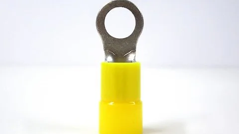
4. Insulation Displacement Connection (IDC)
IDC is a method where the contact cuts through the insulation of the wire to make a connection, eliminating the need to strip the wire. It is the standard for ribbon cables and telecommunications (like Ethernet jacks).
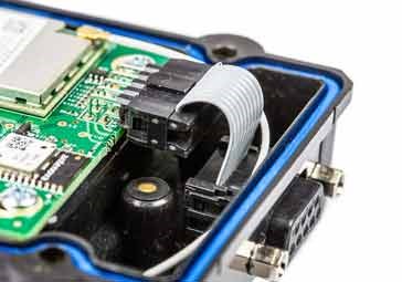
Figure 7. Example of IDC connectors
VI Development Characteristics
As electronic devices evolve, electrical connectors are developing in several key directions:
Miniaturization: Decreasing pitch sizes (down to 0.35mm or less) to fit compact consumer electronics.
High-Speed Transmission: Moving beyond Gbps into Tbps aggregate bandwidths to support AI and Big Data.
High-Power: Handling higher currents for EV charging and battery systems.
Signal Integrity (SI): Advanced designs to minimize crosstalk and insertion loss.
While parallel synchronous transmission has reached its physical limits, high-speed serial transmission has become the standard. Originally dominated by LVDS (Low Voltage Differential Signaling), the industry has now moved towards advanced standards like PCIe Gen 5/6, USB4, and 112G/224G PAM4 SerDes technology.
Key technologies in modern high-speed connector design include:
Differential Signaling: Using paired lines to reject common-mode noise and crosstalk.
Skew Control: Strictly managing the physical length of contact pairs to ensure signals arrive simultaneously.
Impedance Matching: Maintaining a characteristic impedance (usually 50Ω, 85Ω, or 100Ω) throughout the connector to prevent signal reflection.
 UTMEL
UTMEL
We are the professional distributor of electronic components, providing a large variety of products to save you a lot of time, effort, and cost with our efficient self-customized service. careful order preparation fast delivery service
1.What are different types of connectors?
Box-to-box or input/output.
Wire-to-board.
Chip-to-package.
Package-to-board.
PC board-to-board.
2.What are the 3 types of connectors?
Electrical connectors are classified into three types based on their termination ends: board-to-board connectors, cable/wire-to-cable/wire connectors, and cable/wire-to-board connectors. Six levels of interconnection are normally seen in electrical connectors.
3.What are the best electrical connectors?
Weilder Heat Shrink Wire Connectors Kit.
Wirefy Heat Shrink.
Glarks 540 Pieces.
Eventronic 200 Pieces.
Wirefy 120 Pieces.
4.Which tool is used to attach connectors to wires?
Pliers are tools for gripping and cutting wires or connectors.
5.How do you connect wires?
What you need: a roll of electrical tape and two wires whose ends have been twisted together. First, lay the twisted part of the wires onto a strip of electrical tape. Wrap the tape around the wires tightly 5-6 times, making sure to cover up all the wire. Give your connection a tug to make sure it is strong.
 The Introduction to USB Type-C Pin Signal and PCB LayoutUTMEL03 December 202126794
Hello everyone. Welcome to the new post today. USB Type-C is a smaller-volume USB interface standard than Type-A and Type-B. It can be used on a PC (master device) as well as external devices (slave devices, such as mobile phones).
Read More Everything You Need to Know about ConnectorsUTMEL07 September 20218391
Electrical connectors, as key components for current or signal connections, are also an important part of the industrial system. Connectors can be as huge as airplanes and rockets or as small as mobile phones and televisions, forming bridges between circuits or other components and serving as electric current or signal links.
Read More Network Interface Card: Types, Functions and Buying GuideUTMEL17 August 202110626
Network Interface Card (NIC, also known as a network interface controller) is one of the most basic components in the local area network. It is the hardware device connecting the computer and the network. Whether it is a twisted pair connection, a coaxial cable connection, or an optical fiber connection, data communication must be realized with the help of a network interface card.
Read More?") What is Universal Serial Bus (USB)?UTMEL12 June 202612758
What is Universal Serial Bus (USB)?UTMEL12 June 202612758Universal Serial Bus (USB) is a serial bus standard and a technical specification for input and output interfaces. It is widely used in information communication devices. The latest generation is USB4, and its transmission speed is 40Gbit/s, the three-stage voltage is 5V/12V/20V, the maximum power supply is 100W.
Read More Classification and Selection of Industrial ConnectorsUTMEL11 February 20225889
This article mainly introduces a very important component-connector in the modern industrial system, including its definition, classification, and selection.
Read More
Subscribe to Utmel !
![SLJ52GLA080ALMCC8IXHSA1]() SLJ52GLA080ALMCC8IXHSA1
SLJ52GLA080ALMCC8IXHSA1Infineon
![SLJ52GCA036BLM51XHSA1]() SLJ52GCA036BLM51XHSA1
SLJ52GCA036BLM51XHSA1Infineon
![BCV61B215]() BCV61B215
BCV61B215NXP
![BCV62B235]() BCV62B235
BCV62B235NXP
![948159]() 948159
948159Intel
![SLJ52GDL080CLMCC8XHSA1]() SLJ52GDL080CLMCC8XHSA1
SLJ52GDL080CLMCC8XHSA1Infineon
![DFR0853]() DFR0853
DFR0853DFRobot
![SC0165]() SC0165
SC0165Raspberry Pi
![104020228]() 104020228
104020228Seeed
![1970004556T000]() 1970004556T000
1970004556T000Advantech