
 Product
 Brand
Brand Articles
 Tools
Tools
Understanding of Carbon Film Resistors
Carbon Film Resistors Explained
Table of Contents
V. Carbon Film vs. Metal Film Resistors
I. What is a Carbon Film Resistor?
Carbon film resistors are manufactured by depositing a thin carbon film onto an insulating ceramic substrate through thermal decomposition of gaseous hydrocarbons under high temperature and vacuum conditions. The process involves decomposing hydrocarbon gases, which deposit carbon onto ceramic rods or tubes to form a crystalline carbon film. The resistance value can be adjusted by varying the thickness of the carbon film or by cutting helical grooves into the film to modify its effective length and cross-sectional area.
While carbon film resistors have relatively modest electrical performance and stability compared to more advanced resistor types, they offer significant cost advantages. They excel particularly in high-resistance and high-voltage applications, where the thin carbon film can be easily engineered to achieve resistance values in the megohm range.
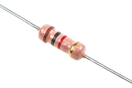
Figure 1. Carbon Film Resistor
Common lead configurations for carbon film resistors include axial lead (most common), radial lead, and surface-mount varieties. The resistance range typically spans from 1Ω to 10MΩ, with rated power options of 0.125W, 0.25W, 0.5W, 1W, 2W, 5W, and 10W available depending on the physical size and construction.
The primary function of carbon film resistors is to impede current flow in electronic circuits. They are widely used for current limiting, voltage division, signal conditioning, load matching, filter networks with capacitors, and impedance matching applications across various electronic devices.
II. Structure and Features of Carbon Film Resistors
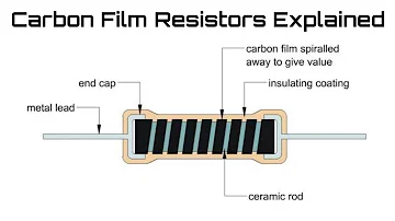
1. Basic Construction
Carbon film resistors utilize specialized equipment to thermally decompose gaseous hydrocarbons in a high-temperature, vacuum environment. The decomposed carbon is uniformly deposited onto the circumferential surface of a ceramic cylinder or tube, forming a crystalline carbon film. The resistance value is determined by adjusting the carbon film thickness and cutting a helical groove with specific pitch to achieve the desired cross-sectional area and effective length of the conductive path.
After the film deposition, metal end caps (typically nickel-plated copper) are attached, leads are soldered, and a protective epoxy coating is applied to the surface to protect against environmental factors and mechanical damage.

Figure 2. Internal Structure of a Carbon Film Resistor
As shown in the figure, the width of the carbon film is inversely proportional to the resistance value, while the effective length is directly proportional. Additionally, thinner carbon films produce higher resistance values. The tolerance of carbon film resistors typically ranges from ±5% to ±10%, with precision versions available at ±2% tolerance. Carbon film resistors exhibit a negative temperature coefficient (NTC), meaning their resistance decreases as temperature increases, typically around -200 to -1000 ppm/°C.
2. Typical Characteristics
(1) Tolerance: Available in tolerances from ±2% to ±10%, with ±5% being most common. The resistance value can be fine-tuned by cutting threads into the film to create precision resistors.
(2) Resistance Range: Wide resistance range, typically from 1Ω to 10MΩ, with some specialized versions reaching up to 100MΩ for high-voltage applications.
(3) Nominal Resistance: E-24, E-48, and E-96 series available depending on tolerance grade.
(4) High Voltage Rating: Can handle high voltages, with some types rated for several kilovolts depending on physical size and construction.
(5) Long-term Stability: Good long-term stability with voltage changes having minimal effect on resistance value. Features a negative temperature coefficient.
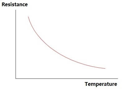
Figure 3. Negative Temperature Coefficient Behavior
(6) Packaging: Available in tape and reel, bulk, or individual bagging for through-hole mounting.
(7) High-Frequency Performance: Good high-frequency characteristics suitable for RF and ultra-high-frequency applications, with inherent noise voltage below 10μV/V.
(8) Rated Power: Available in 1/8W, 1/4W, 1/2W, 1W, 2W, 5W, and 10W ratings.
(9) Pulse Stability: Stable under pulse loading with good adaptability to pulse circuits. Wide application range suitable for AC, DC, and pulse circuits.
III. Carbon Film Resistors: Parameters and Error Rates
1. Key Parameters
The resistance value marked on the resistor is called the nominal value, expressed in Ω (ohms), kΩ (kilohms), or MΩ (megohms). The conversion relationship is: 1MΩ = 1,000kΩ and 1kΩ = 1,000Ω. Nominal values follow standardized series (E-series) established by international standards, not arbitrary values chosen by manufacturers. Carbon film resistors typically range from 1Ω to 10MΩ.
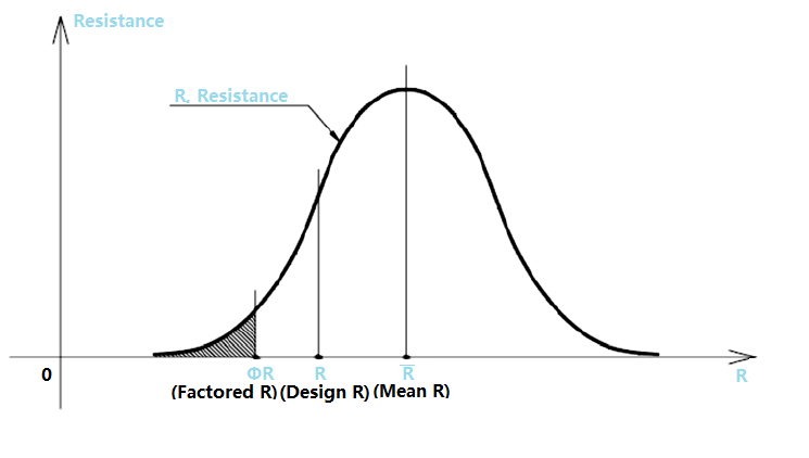
Figure 4. Mean Resistance, Design (Nominal) Resistance, and Factored Resistance
(1) Tolerance
The maximum allowable deviation of the actual resistance from the nominal value is called tolerance. Common tolerance codes: F (±1%), G (±2%), J (±5%), K (±10%), M (±20%).
(2) Rated Power
The rated power is the maximum power the resistor can continuously dissipate under specified ambient temperature (typically 70°C) without damage or significant performance degradation. For carbon film resistors, the power rating is not usually marked on the body but is indicated by the physical size—larger diameter and length correspond to higher power ratings. Common power ratings include 0.125W, 0.25W, 0.5W, 1W, 2W, 5W, and 10W.
Figure 5. Resistor Size Comparison by Power Rating
Miniature carbon film resistors with power ratings as low as 0.0625W (1/16W) are also available for space-constrained applications, often manufactured as color-coded resistors.
2. Error Rates and Tolerance Classifications
Carbon film resistors are available in several tolerance grades:
±2% (Precision grade)
±5% (Standard grade, most common)
±10% (General purpose)
±20% (Economy grade)
Carbon film resistors are typically marked with the designation "RT" where R represents resistor and T indicates carbon film construction. For example, "RT47kJ" denotes a carbon film resistor with 47kΩ resistance and ±5% tolerance.
IV. Marking Methods for Carbon Film Resistors
1. Direct Marking Method
Numbers and unit symbols are printed directly on the resistor surface to indicate the resistance value. Tolerance is expressed as a percentage. If no tolerance is marked, ±20% is assumed.
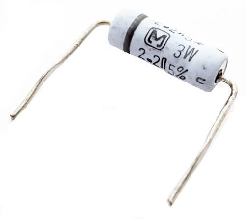
Figure 6. Direct Marking Method Example
2. Text Symbol Method
A combination of Arabic numerals and text symbols indicates the nominal resistance value. The number before the symbol represents the integer resistance value, while subsequent numbers represent decimal places. For example, "4R7" means 4.7Ω, and "4K7" means 4.7kΩ.
3. Digital Method
Three digits are marked on the resistor to indicate the nominal value. The first two digits are significant figures, and the third digit is the multiplier (number of zeros to add). The unit is ohms. For example, "473" represents 47,000Ω or 47kΩ.
4. Color Code Method
Different colored bands or dots indicate the nominal resistance value and tolerance. The color code is: Black-0, Brown-1, Red-2, Orange-3, Yellow-4, Green-5, Blue-6, Violet-7, Gray-8, White-9, Gold-0.1, Silver-0.01.

Figure 7. How to Read Resistor Color Codes
Four-Band Resistors: The last band is gold or silver (tolerance). First two digits are significant figures, third digit is the multiplier, and fourth digit is tolerance.
Five-Band Resistors: Used for higher precision. First three digits are significant figures, fourth digit is the multiplier, and fifth digit is tolerance. The spacing before the last band is typically larger.
V. Carbon Film Resistors vs. Metal Film Resistors
Metal film resistors are manufactured using vacuum deposition technology to apply a thin layer of nickel-chromium or similar alloy onto a ceramic substrate. The film is then cut with a helical groove to achieve the precise resistance value. Metal film resistors offer wider resistance ranges with superior accuracy, tighter tolerances (commonly ±1% or better), and better temperature stability than carbon film resistors.
Carbon film resistors are widely used in consumer electronics and general-purpose applications due to their low cost and reliable performance. They are manufactured by depositing carbon film onto ceramic substrates through thermal decomposition in high-temperature vacuum conditions. While less precise than metal film resistors, carbon film types offer excellent value for non-critical applications.
Visual Identification Methods
Color Bands: Metal film resistors typically use five color bands (±1% tolerance), while carbon film resistors commonly use four bands (±5% tolerance).
Body Color: Metal film resistors often have blue bodies, while carbon film resistors are typically beige, tan, or other colors. However, this is not always reliable as colors vary by manufacturer.
Reliable Differentiation Methods
Method 1 - Film Color Test: Carefully scrape away the protective coating with a blade. Carbon film resistors will reveal a black film layer, while metal film resistors will show a bright metallic (silvery) film.
Method 2 - Temperature Coefficient Test: Since metal film resistors have a much smaller temperature coefficient than carbon film resistors, measure the resistance value with a multimeter, then bring a hot soldering iron near (not touching) the resistor. A significant resistance change indicates a carbon film resistor, while minimal change suggests a metal film resistor.
Figure 8. Temperature Coefficient Testing with Soldering Iron
Key Comparison
| Characteristic | Carbon Film | Metal Film |
|---|---|---|
| Tolerance | ±2% to ±10% | ±0.1% to ±2% |
| Temperature Coefficient | -200 to -1000 ppm/°C | ±50 to ±100 ppm/°C |
| Noise | Moderate | Very Low |
| Cost | Lower | Higher |
| Typical Applications | General purpose circuits | Precision circuits, audio |
VI. Why Resistance Increases and How to Adjust It
1. Reasons for Resistance Increase
Several factors can cause the resistance value of carbon film resistors to increase over time:
(1) Oxidation
Oxidation is a long-term aging mechanism that begins at the resistor surface and gradually penetrates deeper. The oxidation process increases resistance values, with thinner films being more susceptible. While organic protective coatings (plastics, resins, epoxy) can slow oxidation, they may also introduce moisture permeability issues. High temperature and humidity environments significantly accelerate oxidation and aging.
(2) Gas Adsorption and Desorption
Carbon film resistors manufactured in vacuum conditions may adsorb atmospheric gases when exposed to normal pressure, causing resistance increases. Proper aging of semi-finished products at atmospheric pressure before final assembly can improve long-term stability.
Figure 9. Gas Adsorption Effects on Carbon Film
(3) Film Defects and Contamination
Porosity or defects in the carbon film, presence of mobile ions (Na⁺, K⁺, Cl⁻), or inadequate protective coating can lead to degradation and resistance drift.
(4) Terminal Connection Issues
Poor contact between the carbon film and end caps, or loose terminal connections can cause intermittent or permanent resistance increases.
(5) Manufacturing Quality
The quality of raw materials, particularly the carbon deposition process and uniformity, significantly affects long-term stability.

Figure 10. Carbon Black Paste
Explanation: The longer the resistor is being used, the greater the temperature changes. Under normal temperature, the temperature of the resistor cannot be lower than the normal temperature, so the resistance value will only increase rather than decrease.
Reasons: Carbon film resistors have excellent long-term stability. The change in voltage has little effect on the resistance value. And it has a negative temperature coefficient, which means the higher the temperature is, the smaller the resistance will be.
2. Increase the Resistance Manually
Increase the resistance value by scraping the film. Take a resistor with a resistance value slightly smaller than the required value, scrape off the paint film on the surface until the carbon film is exposed.
Measure the resistance while scraping, and stop when you reach the required resistance value.
The ideal range of "added value" should be controlled within 20% of the original resistance value, such as from 1kQ to 1.2kQ.
Note: Increasing the resistance value too much will affect the stability of the resistance.
VII. Latest Applications for Carbon Film Resistors
As of 2025, carbon film resistors continue to play an important role in modern electronics despite the increasing prevalence of surface-mount technology and more advanced resistor types. Their unique combination of cost-effectiveness, availability, and reliable performance ensures their continued relevance across multiple application domains.
1. Consumer Electronics and General-Purpose Applications
Carbon film resistors remain the workhorse component in countless consumer electronic devices where cost optimization is critical and precision requirements are moderate. They are extensively used in:
Power Supply Circuits: Voltage divider networks, current sensing, and load regulation in AC-DC converters, linear regulators, and switching power supplies.
LED Lighting: Current limiting resistors for LED drivers in residential, commercial, and automotive lighting systems.
Home Appliances: Control circuits in washing machines, refrigerators, microwave ovens, and air conditioning systems.
Audio Equipment: Bias networks, signal conditioning, and non-critical audio paths in budget-friendly audio devices, portable speakers, and amplifiers.
2. Industrial and Automation Systems
Industrial applications leverage carbon film resistors for their robustness and wide operating temperature range:
Motor Control Systems: Pull-up/pull-down resistors in digital control circuits, gate resistors for power transistors and IGBTs.
Sensor Interfaces: Signal conditioning for temperature sensors, pressure transducers, and proximity sensors in industrial automation.
PLC Systems: Input/output signal conditioning, termination networks, and isolation circuits in programmable logic controllers.
HVAC Controls: Temperature sensing circuits and control logic in building automation systems.
3. Educational and Prototyping Applications
Carbon film resistors are particularly valuable in educational settings and rapid prototyping due to their through-hole packaging and ease of use:
Electronics Education: Preferred choice for teaching basic circuit theory, breadboard experiments, and laboratory exercises in universities and technical schools worldwide.
Maker Community: Extensively used in Arduino, Raspberry Pi, and other microcontroller projects due to their affordability and ease of soldering.
Prototype Development: Ideal for proof-of-concept circuits and functional prototypes before transitioning to surface-mount alternatives in production.
4. High-Voltage Applications
One area where carbon film resistors excel over many alternatives is in high-voltage circuits:
CRT and Display Technology: While CRT televisions are largely obsolete, high-voltage carbon film resistors continue to be used in oscilloscopes, industrial displays, and specialized imaging equipment.
Medical Equipment: X-ray generators, electrosurgical units, and defibrillators require high-voltage, high-resistance components where carbon film resistors remain cost-effective.
Scientific Instruments: Mass spectrometers, electron microscopes, and particle accelerators use carbon film resistors in voltage divider chains capable of handling several kilovolts.
Electrostatic Applications: Air purifiers, electrostatic precipitators, and photocopier charging systems.
5. Automotive Electronics
The automotive industry continues to utilize carbon film resistors in non-critical applications:
Dashboard Instruments: Gauge circuits, indicator lights, and display backlighting.
Comfort Systems: Climate control panels, seat heating circuits, and interior lighting.
Infotainment Systems: Non-critical signal paths in radio, navigation, and entertainment systems.
Aftermarket Accessories: Dash cameras, parking sensors, and auxiliary lighting systems.
Note: Safety-critical automotive applications (ABS, airbags, engine control) typically require more stable resistor types such as thick film or metal film resistors that meet stringent AEC-Q200 automotive qualification standards.
6. Renewable Energy Systems
The growing renewable energy sector has created new applications for carbon film resistors:
Solar Panel Systems: Voltage sensing, current limiting, and control circuits in charge controllers and inverters.
Wind Turbine Controllers: Signal conditioning and protection circuits in pitch control and power management systems.
Battery Management: Temperature compensation and balancing circuits in lithium-ion battery packs for energy storage systems.
7. IoT and Smart Devices
Despite the miniaturization trend favoring surface-mount components, carbon film resistors find niches in IoT applications:
Smart Home Devices: Control circuits for smart plugs, wireless switches, and environmental sensors.
Wearable Devices: Non-critical signal conditioning in larger form-factor wearables and fitness trackers.
Agricultural IoT: Soil moisture sensors, weather stations, and automated irrigation controllers deployed in harsh outdoor environments.
8. Repair and Maintenance Markets
A significant but often overlooked application area is the repair and refurbishment sector:
Legacy Equipment Repair: Maintaining industrial machinery, medical devices, and telecommunications equipment manufactured before the widespread adoption of surface-mount technology.
Vintage Electronics Restoration: Restoring classic audio equipment, synthesizers, guitar amplifiers, and retro gaming consoles where original through-hole components are preferred for authenticity.
Field Service: Quick repairs and on-site troubleshooting where through-hole components are easier to replace with basic soldering equipment.
9. Current Market Trends and Future Outlook
As of 2025, several trends are shaping the carbon film resistor market:
Declining but Stable Demand: While overall market share is decreasing in favor of chip resistors for high-volume production, through-hole carbon film resistors maintain a steady presence in specific applications.
Geographic Shifts: Production has concentrated in Asia, particularly China, Taiwan, and Southeast Asia, with reduced manufacturing in North America and Europe.
Quality Improvements: Modern manufacturing techniques have improved tolerance consistency and long-term stability compared to older production methods.
Environmental Considerations: RoHS and REACH compliance is now standard, with lead-free terminations and halogen-free coatings becoming universal.
Price Pressures: Intense competition has driven prices down, making carbon film resistors even more attractive for cost-sensitive applications.
Looking Ahead: 2025 and Beyond
While carbon film resistors are considered a mature technology, they are expected to remain relevant for at least the next decade in the following areas:
Education and training, where their visibility and ease of use make them ideal teaching tools
Prototyping and low-volume production where tooling costs for SMT assembly are prohibitive
High-voltage applications where their construction offers advantages over alternatives
Repair markets for legacy equipment expected to remain in service for decades
Regions with developing electronics industries where through-hole assembly infrastructure is more accessible than advanced SMT capabilities
The continued evolution of electronics will likely see carbon film resistors gradually replaced by surface-mount alternatives in most new designs, but their simplicity, robustness, and cost-effectiveness ensure they will remain a fundamental component in the electronics industry for years to come.
Article Recommended:
Beginners Guide to Precision Resistors
What are the Differences Between Pull up and Pull down Resistors?
Analysis of Resistors in Series and Parallel
 UTMEL
UTMEL
We are the professional distributor of electronic components, providing a large variety of products to save you a lot of time, effort, and cost with our efficient self-customized service. careful order preparation fast delivery service
What is a carbon film resistor?
What is a carbon film resistor? Carbon film resistors are a fixed form type resistor. They are constructed out of a ceramic carrier with a thin pure carbon film around it, that functions as resistive material.
Which is better metal film or carbon film resistors?
Metal Oxide film resistors have a better voltage coefficient and temperature coefficient than carbon film resistors. ... As a matter of fact, metal oxide film resistors work in a wide resistance range and can withstand a higher temperature than the carbon film resistors.
Where can I buy carbon film resistors?
Carbon Film Resistors are available at Mouser Electronics from industry leading manufacturers. Mouser is an authorized distributor for many carbon film resistor manufacturers including KOA, Vishay, Yageo, Xicon & many more.
What is the characteristics of carbon film resistor?
Carbon film resistor has high negative temperature co-efficient of resistance. The rate at which the resistance of the material decreases with increase in temperature is called negative temperature co-efficient of resistance. Carbon film resistors have high negative temperature co-efficient of resistance.
Are carbon film resistors noisy?
Carbon Comps and Films are noisy and make amps have more hiss, pops, and sizzle. ... Carbon films are a little quieter but not as quiet as metal film, metal oxide or wirewound resistors. Over time they can drift in value so they need to be replaced for the amp to sound the same or even work correctly.
 What are the Differences Between Pull up and Pull down Resistors?UTMEL22 October 202539118
Pull up is to clamp an uncertain signal to a high level with a resistor, and the resistor also acts as a current limiter. In the same way, pull down means to clamp the uncertain signal to a low level through a resistor. To pull up is to input current to the device, and the pull-down is to output the current.
Read More Rheostat Basics: Types, Principle and FunctionsUTMEL25 December 202518764
A rheostat is a device that can adjust the size of the resistance and can be connected to the circuit to adjust the size of the current. A general rheostat is composed of a wire with a larger resistance and a device that can change the contact point to adjust the effective length of the resistance wire. Rheostat can limit the current and protect the circuit, and change the voltage distribution in the circuit.
Read More Basic Introduction to Metal Film ResistorUTMEL28 August 202014026
Metal film resistors are a kind of film resistors. Metal film resistors are resistors in which special metals or alloys are used as resistor materials, and the resistor film layer is basically formed on ceramic or glass by vacuum evaporation or sputtering.
Read More Varistor: Definition, Function, Working and TestingUTMEL03 April 202584377
A varistor is a device with a non-linear volt-ampere characteristic. When the voltage applied to the varistor is lower than its threshold value, the current flowing through it is extremely small, which is equivalent to a resistor with infinite resistance, vice versa. The most common varistor is a metal oxide varistor (MOV).
Read More Photoresistor Basics: Types, Principles and ApplicationsUTMEL16 October 202546964
The article introduces the photoresistor’s main characteristics and principles including the working principle and structural principle. There are three types of photoresistor: ultraviolet photoresistors, infrared photoresistors, visible light photoresistors. Dimming circuit and light switch are the two applications of the photoresistor.
Read More
Subscribe to Utmel !
![HMC406MS8GE]() HMC406MS8GE
HMC406MS8GEAnalog Devices Inc.
![ADL5387ACPZ-WP]() ADL5387ACPZ-WP
ADL5387ACPZ-WPAnalog Devices Inc.
![ALM-2812-BLKG]() ALM-2812-BLKG
ALM-2812-BLKGBroadcom Limited
![D5PE942M5P3GT-Z]() D5PE942M5P3GT-Z
D5PE942M5P3GT-ZTaiyo Yuden
![ADEX-10L]() ADEX-10L
ADEX-10LMini-Circuits
![MGA-30989-TR1G]() MGA-30989-TR1G
MGA-30989-TR1GBroadcom Limited
![ADL5320ARKZ-R7]() ADL5320ARKZ-R7
ADL5320ARKZ-R7Analog Devices Inc.
![LMV225TLX/NOPB]() LMV225TLX/NOPB
LMV225TLX/NOPBTexas Instruments
![HMC753LP4E]() HMC753LP4E
HMC753LP4EAnalog Devices Inc.
![LTM9003IV-AB#PBF]() LTM9003IV-AB#PBF
LTM9003IV-AB#PBFLinear Technology/Analog Devices


