
 Product
 Brand
Brand Articles
 Tools
Tools
What is a Variable Resistor?

Variable Resistors Explained
Executive Summary: A variable resistor is a crucial electromechanical component used to dynamically adjust circuit resistance, controlling current (as a rheostat) or dividing voltage (as a potentiometer). In 2026, these components remain foundational in everything from precision industrial robotics to smart home IoT devices, offering reliable, manual control over electrical parameters.
A variable resistor is an electromechanical component whose resistance can be adjusted by moving a wiper across its resistive element. They serve two main functions: as a rheostat (two-terminal configuration) to control current, or as a potentiometer (three-terminal configuration) to divide voltage.
Contents
1. What Are the Circuit Symbols of Variable Resistors?
Variable resistors are represented in circuit diagrams using specific symbols that indicate their adjustability and terminal configuration, typically featuring a standard resistor zigzag line with a diagonal or perpendicular arrow.

Figure 1: Standard variable resistor (two-terminal) and potentiometer (three-terminal) symbols

Figure 2: Traditional variable resistor symbol (two-terminal configuration)

Figure 3: Potentiometer symbol (three-terminal configuration)
Variable resistors are represented in circuit diagrams using specific symbols:
Standard symbol (Figure 1): A resistor with an arrow through it, indicating adjustability. The letter "R" denotes a resistor, and "W" indicates the wiper terminal.
Traditional symbol (Figure 2): Often found in older circuit diagrams, showing a rheostat configuration where the wiper is connected to one fixed terminal.
Potentiometer symbol (Figure 3): Shows all three terminals as independent connections, functioning as a voltage divider.
Note: Modern circuit diagrams typically use the standard symbol (Figure 1), while older diagrams may use the traditional representation (Figure 2).
2. How Does a Variable Resistor Work?
A variable resistor works by sliding a conductive wiper across a resistive track, which dynamically changes the effective electrical length and alters the resistance between the terminals.

Figure 4: Structure of a small-signal variable resistor
A typical small-signal variable resistor consists of:
Resistive track: Made of carbon film, metal film, or other resistive material
Wiper (moving contact): Slides across the resistive track
Terminals: Two fixed terminals at track ends and one wiper terminal
Adjustment mechanism: Usually a shaft or screw slot
Working Principle
When you rotate the adjustment shaft using a screwdriver:
The wiper (moving contact) slides along the resistive track
This changes the effective length of the resistive material between the wiper and each fixed terminal
As the wiper moves closer to one fixed terminal, resistance decreases between them while increasing between the wiper and the other terminal
The total resistance between the two fixed terminals remains constant
Example: When the wiper is at the extreme left position, resistance between the left terminal and wiper is zero, while resistance between the wiper and right terminal equals the component's full nominal resistance.
3. What Are the Different Types of Variable Resistors?
Variable resistors are primarily classified by their resistive materials—such as carbon film, metal film, or wire-wound—and their enclosure designs, which dictate their power handling and environmental durability.
With the global passive electronic components market expanding rapidly, advanced cermet and conductive plastic variable resistors are increasingly dominating high-cycle applications in 2026. However, traditional types remain highly relevant.
3.1 Film-type Variable Resistors

Figure 5: Carbon film variable resistor
Film-type variable resistors use a synthetic carbon or metal film as the resistive element. They typically employ a rotary adjustment mechanism and are designed for small-signal applications.
Components:
Resistor body (synthetic carbon film)
Movable contact (metal reed or carbon contact)
Adjustment mechanism
Three terminals (two fixed, one moving)
Based on their enclosure design, film-type variable resistors are categorized into:
Full-sealed (Solid)
Made from carbon black, quartz powder, and organic binders
Sealed with metal casing
Excellent dust protection
Reliable contact performance
Semi-sealed
Similar resistor body to fully-sealed type
Uses metal reed for movable contact
Sealed with plastic outer cover
Easier to adjust but less dust-resistant
Non-sealed (Chip Adjustable)
Suspension liquid coated on glass fiberboard or bakelite
Limited dust protection
Contacts prone to oxidation
Higher failure rate
3.2 Wire-Wound Variable Resistors

Figure 9: Wire-wound variable resistor
Wire-wound variable resistors use resistance wire wrapped around an insulating core. They are designed for power applications and offer:
Low noise characteristics
High temperature resistance
Ability to handle large currents
Suitable for voltage/current adjustment in low-frequency circuits
Wire-wound variable resistors are further classified as:
High-power (Sliding Wire) Types
Axial porcelain tube wire-wound
Porcelain disc wire-wound
Designed for high current applications
Low-power Types
Round vertical wire-wound
Round horizontal wire-wound
Square wire-wound
All feature fully sealed package structures
Application Guideline: For general-purpose applications with moderate current, metal variable resistors are recommended. For small currents, carbon film types are optimal. For high current applications, electrolytic variable resistors (with electrodes immersed in conductive liquid) offer the best performance.
4. What Are the Physical Characteristics of Variable Resistors?
The physical characteristics of variable resistors include a larger footprint than fixed resistors, a three-terminal configuration, and a mechanical adjustment shaft or slot for tuning.

Figure 10: Terminal configuration of a variable resistor
Variable resistors have distinct physical characteristics that set them apart from fixed resistors:
Size: Larger than standard resistors, making them easy to identify on circuit boards
Terminal configuration: Three terminals (one moving and two fixed)
Adjustment mechanism: Slot or shaft for screwdriver adjustment
Resistance marking: Shows the nominal (maximum) resistance value
Vertical Variable Resistors
Used in small-signal circuits
Three pins vertically downward
Mounted vertically on the circuit board
Horizontal adjustment port
Horizontal Variable Resistors
Used in small-signal circuits
Pins at 90° angle to the resistor body
Mounted vertically on the circuit board
Upward-facing adjustment port
Important Note: Variable resistors typically have higher failure rates than fixed resistors due to their mechanical components and adjustment mechanisms. This should be considered when designing circuits that require long-term reliability.
5. What Are the Main Functions and Applications in 2026?
In 2026, variable resistors function primarily to adjust circuit current, divide voltage, and calibrate sensitive electronic instruments across automotive, audio, and IoT applications.
Variable resistors serve several critical functions in electronic circuits:
Primary Functions
Adjusting circuit current by varying resistance
Dividing voltage (in potentiometer configuration)
Protecting sensitive components by limiting current
Calibrating electronic instruments
Common Applications
Audio equipment (volume, tone controls)
Light dimmers and smart home lighting systems
Motor speed controllers in industrial robotics
Signal generator characteristics adjustment
Sensor calibration for IoT edge devices
Selection Guide
| Application Type | Recommended Variable Resistor |
|---|---|
| General current applications | Metal-type variable resistors |
| Small current applications | Carbon film type |
| Large current applications | Electrolytic type |
| Audio control | Potentiometers (exponential for volume) |
| Precision applications | Multi-turn potentiometers |
6. What Is a Potentiometer and How Does It Differ?
A potentiometer is a specific three-terminal variable resistor configured to act as an adjustable voltage divider, whereas a standard variable resistor (rheostat) uses only two terminals to control current.

Figure 11: Potentiometer symbols
A potentiometer is a special type of variable resistor that functions as a voltage divider. It divides the voltage applied to its fixed terminals according to the position of the wiper, providing adjustable output voltage.
The potentiometer concept can be compared to a water valve that controls flow, but for electrical signals instead of water. This makes it a crucial component in many electronic devices requiring manual adjustment.
6.1 Types of Potentiometers

Figure 12: Various types of potentiometers
Potentiometers can be categorized based on their construction materials and mechanical design:
By Material:
Carbon film potentiometers
Wire-wound potentiometers
Conductive plastic potentiometers
Cermet (ceramic-metal) potentiometers
By Design:
Rotary potentiometers
Linear sliding potentiometers
Multi-turn potentiometers
Digital/stepper potentiometers
Motorized potentiometers
Advanced Types: With increasing demand for precision audio equipment, specialized potentiometers have been developed:
Stepping potentiometers: Use series and parallel resistor networks to maintain synchronized resistance values in dual-track configurations, critical for stereo audio applications
Electric potentiometers: Incorporate motors that drive the potentiometer through gears, enabling remote control while maintaining the frequency characteristics of traditional potentiometers
6.2 Using Potentiometers
Identifying Potentiometers in Circuits
When working with potentiometers, the first step is to recognize their symbol in circuit diagrams, as illustrated in Figure 13. The second critical step is understanding the relationship between the circuit symbol and the physical potentiometer, particularly the position of the center tap (wiper).

Figure 13: Potentiometer representation in circuit diagrams
Since potentiometers are variable resistors, it's essential to consider both their resistance value and power rating when incorporating them into circuits. While their application principles align with regular resistors, potentiometers are uniquely designated in circuit diagrams with the symbol "RP" (or "W" in older circuit diagrams).
Understanding Resistance Values
The resistance value marked on a potentiometer represents its total resistance. For example, in Figure 13, if the resistance between terminals A and B is 10kΩ, then the resistance values between terminals AC and BC will vary from 0 to 10kΩ as you rotate the wiper.
Pro Tip: Finding the Center Tap
New users often struggle to identify the center tap (wiper terminal) on a potentiometer. To solve this issue, follow these three steps:
Set your multimeter to the resistance (Ohms) mode.
Measure the resistance between different pairs of terminals while rotating the shaft; the pair with constant resistance are the outer terminals (A and B).
Identify the remaining terminal as the center tap (wiper, C), which will show varying resistance when measured against A or B during rotation.
Referring to Figure 13, when the wiper (C) moves closer to terminal A, the resistance between A and C decreases while the resistance between B and C increases. Conversely, when the wiper moves toward B, the AC resistance increases while the BC resistance decreases.
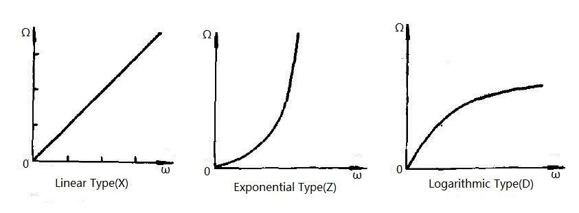
Figure 14: Resistance changing curves for different potentiometer types
Types of Potentiometers by Taper
Potentiometers come in three primary taper types, each with different resistance variation patterns as shown in Figure 14:
Exponential (Z): Resistance changes exponentially with rotation, making fine adjustments possible at one end of the range
Logarithmic (D): Resistance follows a logarithmic curve, ideal for audio applications
Linear (X): Resistance changes uniformly throughout the rotation range
These different taper types make potentiometers suitable for specific applications. For instance, logarithmic potentiometers are preferred for volume control in audio circuits because they match human hearing perception, while linear potentiometers are better suited for balance controls or applications requiring proportional adjustment.
Common Applications
Volume controls (logarithmic)
Light dimmers (linear)
Sensor calibration
Voltage dividers
Motor speed controls
Selection Criteria
Total resistance value
Power rating
Taper type (linear/log/exponential)
Mechanical design (rotary/slider)
Environmental considerations
Conclusion
This article has introduced the fundamental aspects of potentiometers, including their circuit symbols, structure, and functionality. We've explored the different taper types—exponential, logarithmic, and linear—and their specific applications. Understanding these characteristics enables you to select the appropriate potentiometer for your electronic projects, whether you're working with audio circuits, lighting controls, or precision measurement systems.
Recommended Articles
Frequently Asked Questions
What is the difference between a variable resistor and a potentiometer?
A variable resistor (rheostat) uses two terminals to control current flow in a circuit. A potentiometer uses all three terminals to act as a voltage divider. While all potentiometers can be wired as variable resistors, not all variable resistors can function as potentiometers.
How do you test a variable resistor with a multimeter?
To test a variable resistor, set your multimeter to the ohms (Ω) setting. Connect the probes to the two outer terminals to verify the total resistance. Then, move one probe to the center wiper terminal and turn the shaft; the resistance should change smoothly without sudden drops.
Can I use a potentiometer as a rheostat?
Yes, you can use a potentiometer as a rheostat by connecting only two of its terminals: the center wiper and one of the outer fixed terminals. It is recommended to tie the unused outer terminal to the wiper to prevent circuit interruption if the wiper loses contact.
Why do variable resistors fail?
Variable resistors typically fail due to mechanical wear, dirt accumulation on the resistive track, or thermal overload. In 2026, environmental sealing has improved, but repeated friction from the wiper eventually degrades the carbon or metal film, leading to "scratchy" outputs or dead spots.
 UTMEL
UTMEL
We are the professional distributor of electronic components, providing a large variety of products to save you a lot of time, effort, and cost with our efficient self-customized service. careful order preparation fast delivery service
1.What is a variable resistor?
A variable resistor is a resistor of which the electric resistance value can be adjusted. When a variable resistor is used as a potential divider by using 3 terminals it is called a potentiometer. When only two terminals are used, it functions as a variable resistance and is called a rheostat.
2.What is a variable resistor used for?
A resistor limits the passage of electrical current. A fixed resistor has a resistance that does not change. The resistance of this resistor is changed by moving the position of a slider. A variable resistor is used in some dimmer switches and volume controls.
3.What is an example of a variable resistor?
Variable Resistors are resistors whose resistance values can vary according to some factor applied to them. For example, potentiometers are variable resistors that change when a user adjusts the knob. Photoresistors are variable resistors that change according to the light that strikes their surface.
4.How do variable resistors work?
A variable resistor works by adjusting the path that the current has to flow. Inside the resistor is a strip of metal or conducting ceramic that is connected to one part of the circuit. The dial you turn will move another piece of wire inside the resistor.
5.What are three common types of variable resistors?
The different types of variable resistors include:
Potentiometer.
Rheostat.
Thermistor.
Magneto resistor.
Photoresistor.
Humistor.
Force-sensitive resistor.
 What are the Differences Between Pull up and Pull down Resistors?UTMEL22 October 202539168
Pull up is to clamp an uncertain signal to a high level with a resistor, and the resistor also acts as a current limiter. In the same way, pull down means to clamp the uncertain signal to a low level through a resistor. To pull up is to input current to the device, and the pull-down is to output the current.
Read More Rheostat Basics: Types, Principle and FunctionsUTMEL25 December 202518804
A rheostat is a device that can adjust the size of the resistance and can be connected to the circuit to adjust the size of the current. A general rheostat is composed of a wire with a larger resistance and a device that can change the contact point to adjust the effective length of the resistance wire. Rheostat can limit the current and protect the circuit, and change the voltage distribution in the circuit.
Read More Basic Introduction to Metal Film ResistorUTMEL28 August 202014046
Metal film resistors are a kind of film resistors. Metal film resistors are resistors in which special metals or alloys are used as resistor materials, and the resistor film layer is basically formed on ceramic or glass by vacuum evaporation or sputtering.
Read More Varistor: Definition, Function, Working and TestingUTMEL03 April 202584443
A varistor is a device with a non-linear volt-ampere characteristic. When the voltage applied to the varistor is lower than its threshold value, the current flowing through it is extremely small, which is equivalent to a resistor with infinite resistance, vice versa. The most common varistor is a metal oxide varistor (MOV).
Read More Photoresistor Basics: Types, Principles and ApplicationsUTMEL16 October 202547017
The article introduces the photoresistor’s main characteristics and principles including the working principle and structural principle. There are three types of photoresistor: ultraviolet photoresistors, infrared photoresistors, visible light photoresistors. Dimming circuit and light switch are the two applications of the photoresistor.
Read More
Subscribe to Utmel !
![RN2483A-I/RM103]() RN2483A-I/RM103
RN2483A-I/RM103Microchip Technology
![HMC490]() HMC490
HMC490Analog Devices Inc.
![CC1070RSQ]() CC1070RSQ
CC1070RSQTexas Instruments
![HMC361]() HMC361
HMC361Analog Devices Inc.
![CC1070RSQR]() CC1070RSQR
CC1070RSQRTexas Instruments
![TDA7786C]() TDA7786C
TDA7786CSTMicroelectronics
![LTC5587IDD#PBF]() LTC5587IDD#PBF
LTC5587IDD#PBFLinear Technology/Analog Devices
![LTC5536ES6#TRMPBF]() LTC5536ES6#TRMPBF
LTC5536ES6#TRMPBFLinear Technology/Analog Devices
![CC1050PWR]() CC1050PWR
CC1050PWRTexas Instruments
![HMC859LC3]() HMC859LC3
HMC859LC3Analog Devices Inc.


