
 Product
 Brand
Brand Articles
 Tools
Tools
What are Laser Diodes?

What is a Laser Diode?
Table of Contents
II. Working Principle of Laser Diodes
III. Luminescence Theory of Laser Diodes
IV. Physical Structure and Performance of Laser Diodes
V. Testing Methods and Precautions
2. Important Safety and Handling Guidelines
VI. Laser Diode Drive Circuit Diagrams
1. Automatic Power Control Circuit
2. Advanced Constant Current Drive Circuit
3. Simple Common Emitter Drive Circuit
I. Laser Diode Parameters
● Wavelength: The operating wavelength of the laser diode. Common wavelengths for photoelectric applications include 405nm (violet), 450nm (blue), 520nm (green), 635nm, 650nm, 670nm, 690nm (red), 780nm, 808nm, 830nm, 850nm, 980nm (infrared), and 1310nm, 1550nm (telecommunications). The wavelength directly determines the application, with visible wavelengths used in displays, pointers, and consumer electronics, while infrared wavelengths are prevalent in telecommunications, sensing, and industrial applications.

High-power laser diode suppliers typically offer standard wavelengths across the spectrum
● Threshold Current (Ith): The minimum current required for the laser diode to begin lasing. Below this threshold, the device operates as an LED emitting spontaneous, incoherent light. For modern low-power laser diodes, threshold currents typically range from 10-50 mA. Advanced structures such as strained multiple quantum well (MQW) designs can achieve threshold currents below 5 mA, significantly improving efficiency and thermal performance.
● Operating Current (Iop): The drive current required for the laser diode to reach its rated output power. This parameter is critical for designing drive circuits and ensuring stable operation. Operating currents typically range from 30 mA for low-power pointer applications to several amperes for high-power industrial lasers.
● Vertical Divergence Angle (θ⊥): The angular spread of the laser beam perpendicular to the PN junction, typically ranging from 15° to 40°. This asymmetric beam profile is due to the rectangular geometry of the active region and requires collimation optics for most applications.
● Horizontal Divergence Angle (θ∥): The angular spread parallel to the PN junction, typically ranging from 6° to 10°. The difference between vertical and horizontal divergence angles necessitates cylindrical lenses or anamorphic prism pairs to create a circular beam profile.
● Monitor Current (Im): The photodiode current generated by the integrated monitoring photodiode when the laser operates at rated power. This parameter is essential for automatic power control (APC) circuits that maintain stable output power despite temperature variations and aging effects. Typical monitor currents range from 50 μA to several mA.
Modern Applications: As of 2025, laser diodes have expanded beyond traditional applications into cutting-edge fields including LiDAR for autonomous vehicles, quantum computing, advanced medical diagnostics and surgery, additive manufacturing (3D printing), high-speed free-space optical communications, augmented reality (AR) and virtual reality (VR) displays, and precision spectroscopy for environmental monitoring.
Laser diodes are now utilized in low-power photoelectric equipment such as optical disc drives, laser printers, barcode scanners, laser ranging systems, laser pointers, and optical communications. They have also become essential in high-power applications including materials processing (cutting and welding), medical surgery, advanced lighting systems, defense applications, and solid-state laser pumping.
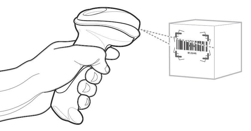
Barcode scanners represent one of many commercial applications for laser diodes
II. Working Principle of Laser Diodes
A laser diode is a semiconductor device that generates coherent light through stimulated emission. Three fundamental conditions must be satisfied to produce laser radiation:
Population inversion: Creating a state where more charge carriers exist in the excited state than in the ground state
Threshold conditions: Achieving sufficient gain to overcome optical losses in the cavity
Optical resonance: Establishing a resonant cavity that provides positive feedback for specific wavelengths
⚠ ESD Warning: Laser diodes are extremely sensitive to electrostatic discharge (ESD), with typical failure thresholds below 100V. Always use proper ESD protection including grounded wrist straps, ESD-safe workstations, and proper handling procedures. Even brief exposure to static electricity can cause immediate or latent failures.
Modern laser diodes are classified into several structural types:
Single Heterojunction (SH): Legacy design, rarely used in modern applications
Double Heterojunction (DH): Standard design offering good performance and reliability
Quantum Well (QW): Advanced design with superior efficiency and lower threshold current
Multiple Quantum Well (MQW): Current mainstream technology offering optimal performance
Quantum Dot (QD): Emerging technology for specialized applications requiring narrow linewidth
Quantum well laser diodes offer significant advantages including lower threshold currents (often below 10 mA), higher output power capabilities, improved temperature stability, and longer operational lifetimes exceeding 100,000 hours. These characteristics have made MQW designs the dominant technology in modern applications.
Compared to other laser types, semiconductor laser diodes provide high electrical-to-optical conversion efficiency (typically 30-70%), compact size enabling integration into portable devices, long operational lifetimes, direct current modulation capabilities for high-speed communications, and relatively low cost due to semiconductor manufacturing economies of scale. However, they have limitations including relatively lower output power per device (though this can be overcome with arrays), broader spectral linewidth compared to gas lasers, and temperature-dependent characteristics requiring thermal management.
The basic structure of a semiconductor laser diode consists of a PN junction with parallel end faces perpendicular to the junction plane, forming a Fabry-Pérot resonant cavity:

Basic laser diode construction showing the resonant cavity structure
The parallel end faces can be cleaved crystal surfaces or polished and coated surfaces. Modern laser diodes typically employ specialized coatings: a high-reflection coating (>95% reflectivity) on the rear facet and an anti-reflection or partial-reflection coating (typically 5-30% reflectivity) on the output facet. The remaining perpendicular surfaces are roughened or angled to suppress lasing in unwanted directions.
Light emission in semiconductors results from carrier recombination. When forward voltage is applied to the PN junction, the potential barrier is reduced, allowing electrons to be injected from the N-region into the P-region, and holes from the P-region into the N-region. These non-equilibrium carriers recombine, emitting photons with wavelength λ determined by:
λ = hc / Eg
Where:
h = Planck's constant (6.626 × 10⁻³⁴ J·s)
c = speed of light (2.998 × 10⁸ m/s)
Eg = bandgap energy of the semiconductor material
The phenomenon of photon emission due to spontaneous carrier recombination is called spontaneous emission. When photons generated by spontaneous emission traverse the semiconductor and encounter excited electron-hole pairs, they can stimulate these carriers to recombine, generating additional photons with identical energy, phase, and propagation direction. This process is called stimulated emission, which is the fundamental mechanism enabling laser operation.

Optical output power versus drive current characteristic showing threshold behavior
When the injection current is sufficiently large, it creates a carrier distribution opposite to thermal equilibrium—a condition called population inversion. In this state, stimulated emission dominates over absorption. Photons generated by spontaneous emission undergo multiple reflections between the cavity end faces, stimulating additional emission during each pass. When the optical gain exceeds cavity losses, the system reaches threshold and coherent laser emission begins. This frequency-selective resonance provides positive feedback for specific wavelengths determined by the cavity length and refractive index.
III. Luminescence Theory of Laser Diodes
The PN junction in laser diodes is typically formed using compound semiconductors such as gallium arsenide (GaAs), indium gallium arsenide (InGaAs), aluminum gallium arsenide (AlGaAs), indium gallium nitride (InGaN), or more complex quaternary alloys like indium gallium arsenide phosphide (InGaAsP). The choice of material system determines the emission wavelength and performance characteristics.
The device features two parallel end faces that serve as mirrors: one highly reflective surface (typically >95% reflectivity with specialized coatings) and one partially transmissive output facet (5-30% reflectivity). The cavity length, typically ranging from 250 μm to several millimeters, determines the longitudinal mode spacing and influences the output wavelength.
When the PN junction receives forward bias from an external power source, electrons move across the junction and recombine with holes, similar to a standard LED. However, in a laser diode, the geometry and optical feedback create conditions for stimulated emission. When electrons and holes recombine, they release photons at an energy corresponding to the bandgap. These photons can stimulate further recombinations, creating an avalanche effect.
As forward bias current increases, more carriers enter the active region, increasing photon generation. Eventually, photons traveling perpendicular to the junction facets reflect from the end mirrors and traverse the active region repeatedly. During each pass, they stimulate additional carrier recombination, amplifying the optical signal. The photons undergo multiple round trips, building up intensity through constructive interference.

Active region where carrier recombination and photon emission occur
This repeated reflection and amplification process produces an intense, coherent laser beam. Each photon generated through stimulated emission is identical to the stimulating photon in terms of energy (wavelength), phase, direction, and polarization. This coherence is the defining characteristic distinguishing laser emission from ordinary LED light.
The laser diode must be driven above a specific threshold current to achieve lasing. Below threshold, the device operates as a conventional LED, emitting incoherent spontaneous emission. Above threshold, stimulated emission dominates, and coherent laser output increases rapidly with drive current. The threshold current depends on temperature, cavity design, and material quality, with modern devices achieving thresholds as low as a few milliamperes.
The optical output exhibits a characteristic "kink" at the threshold current, above which output power increases linearly with drive current. This linear region is the normal operating range for most applications, with slope efficiency (power output per unit current increase) typically ranging from 0.1 to 1.0 W/A depending on the device design and wavelength.
IV. Physical Structure and Performance of Laser Diodes
Modern laser diodes incorporate a layer of photoactive semiconductor material between the junction regions. The end surfaces are precision-cleaved or polished and coated with appropriate reflective layers to form an optical resonant cavity. When forward-biased, the junction emits light that interacts with the optical resonator, selectively amplifying specific wavelengths through constructive interference.
Contemporary laser diodes used in applications such as optical storage, telecommunications, and industrial systems typically employ ternary compounds like aluminum gallium arsenide (AlGaAs) or more complex quaternary materials such as indium gallium arsenide phosphide (InGaAsP). These materials feature double heterostructure or multiple quantum well designs that confine both carriers and photons to the active region, dramatically improving efficiency.
For optical disc applications, near-infrared semiconductor laser diodes operating at 780-850 nm were historically common (used in CD players), with rated powers of 3-5 mW. DVD systems use 650 nm (red) laser diodes, while Blu-ray technology employs 405 nm (violet) GaN-based laser diodes, enabling higher data density. Modern applications also utilize visible laser diodes in green (520 nm), blue (450 nm), and red (635-660 nm) wavelengths for displays, projectors, and laser light shows.

Typical laser diode package dimensions and pin configuration
The internal structure of laser diodes comprises two main functional sections:
Laser emission section (LD): The primary PN junction structure that generates coherent laser radiation. In three-pin packages, this corresponds to the laser diode electrode (typically pin 2)
Monitor photodiode section (PD): An integrated photodetector positioned to receive a portion of the rear-emitted laser light. This provides feedback for automatic power control circuits, ensuring stable output despite temperature variations and aging. This corresponds to the monitor photodiode electrode (typically pin 3)
These two sections share a common electrode (pin 1), resulting in the standard three-terminal configuration. Some simplified laser diodes intended for applications not requiring power monitoring may omit the photodiode section, resulting in a two-terminal device.
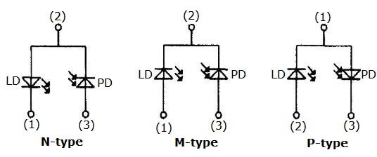
Three common laser diode package configurations and internal structures
Package Evolution: Modern laser diodes are available in various package types including TO-can (TO-18, TO-56, TO-9), butterfly packages for telecommunications, surface-mount packages for high-volume manufacturing, and fiber-coupled modules for integrated systems. The choice of package affects thermal management, optical coupling efficiency, and integration complexity.
V. Testing Methods and Precautions
1. Detection of Laser Diodes
(1) Resistance Measurement
Remove the laser diode from the circuit and measure forward and reverse resistance using a digital multimeter set to the diode test mode or the R×1kΩ to R×10kΩ resistance range. Important: Never use the R×1Ω or R×10Ω ranges, as the test current may exceed safe limits and damage the device.
For a healthy laser diode:
Forward resistance: Typically 20-40 kΩ (varies with multimeter test voltage)
Reverse resistance: Should read as open circuit (∞ or OL)
Performance degradation indicators:
Forward resistance exceeding 50 kΩ suggests performance degradation
Forward resistance exceeding 90 kΩ indicates severe aging; the device should be replaced
Low reverse resistance indicates junction damage or contamination
Similar forward and reverse readings suggest complete junction failure
⚠ Measurement Safety: Always discharge any circuit capacitors before testing. The voltage spike from charged capacitors can instantly destroy laser diodes. Use appropriate ESD precautions during all testing procedures.
(2) Current Measurement
In-circuit current measurement provides valuable diagnostic information without removing the device. Using a digital multimeter, measure the voltage drop across the series current-limiting resistor in the laser diode drive circuit. Calculate the operating current using Ohm's law:
I = Vresistor / Rresistor
Normal operation indicators:
Operating current should be within datasheet specifications (typically 30-100 mA for low-power devices)
Adjusting the power control should produce proportional current changes
Current should be stable without fluctuations
Failure indicators:
Current exceeding 100 mA with no response to power adjustment suggests severe aging
Rapidly increasing or uncontrollable current indicates optical cavity damage
Very low or zero current with proper voltage applied suggests an open circuit
Unstable or fluctuating current may indicate poor electrical connections or drive circuit problems
(3) Optical Output Testing
Proper optical testing requires specialized equipment and should be performed by qualified personnel:
Optical power meter: Measure output power at specified drive current
Spectrum analyzer: Verify wavelength and spectral purity
Beam profiler: Assess beam quality and divergence angles
High-speed photodiode: Evaluate modulation response for communications applications
2. Important Safety and Handling Guidelines
(1) Eye Safety - CRITICAL
⚠ LASER RADIATION HAZARD: Laser diodes emit concentrated radiation that can cause permanent eye damage or blindness, even at low power levels. Class 3B and Class 4 lasers are particularly dangerous. NEVER:
Look directly at the laser diode output facet when energized
View the laser beam through optical instruments (microscopes, telescopes) without proper filters
Direct the beam toward reflective surfaces that could redirect it toward eyes
Operate laser diodes without appropriate safety enclosures in research or industrial settings
Always wear appropriate laser safety eyewear rated for the specific wavelength and power level. Follow all applicable laser safety regulations including ANSI Z136 (US), IEC 60825 (International), and local requirements.
(2) Electrical Drive Requirements
Laser diodes require carefully controlled electrical drive to prevent damage:
Current limiting is mandatory: Never connect laser diodes directly to voltage sources. Always use current-limited power supplies or appropriate current-limiting resistors
Reverse voltage protection: The maximum reverse voltage is typically only 2-3V. Exceeding this causes immediate, irreversible damage. Implement reverse polarity protection in all circuits
Transient protection: Voltage or current spikes during power-up, power-down, or circuit probing can destroy the device. Use soft-start circuits and proper decoupling
Oscilloscope probing: Always disconnect power before attaching oscilloscope probes. The capacitance discharge from probe connection can generate destructive current surges
EMI/RFI immunity: Shield sensitive control circuits from electromagnetic interference that could cause unintended current surges
(3) Environmental Considerations
Cleanliness: Laser diodes must be operated and stored in clean environments. Dust or contamination on the optical facets severely degrades performance or causes catastrophic optical damage (COD)
Humidity control: Excessive humidity can cause corrosion; very low humidity increases ESD risk. Maintain 30-60% relative humidity
Hermetic packaging: For critical applications, use hermetically sealed laser diodes to protect against environmental degradation
(4) Thermal Management - Essential for Reliability
Temperature profoundly affects laser diode performance and lifetime:
Threshold current increase: Threshold current typically increases 1-3% per °C temperature rise
Wavelength shift: Output wavelength shifts approximately 0.2-0.3 nm/°C for most laser diodes
Efficiency reduction: Output power decreases with increasing temperature at constant current
Accelerated aging: Lifetime decreases exponentially with operating temperature. Each 10°C increase approximately halves the expected lifetime
Thermal management solutions:
Adequate heat sinking with low thermal resistance paths
Thermoelectric coolers (TECs) for precision temperature control
Active temperature monitoring with thermistors
Maintain junction temperature below 50°C for optimal lifetime
For high-power applications, water cooling may be necessary
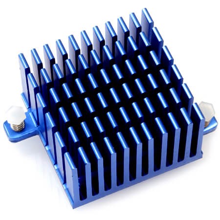
Proper heat sinking is essential for laser diode reliability and longevity
(5) Preventing Output Power Damage
Maximum ratings: Operating above maximum rated current or optical power accelerates degradation exponentially
Optical power monitoring: Use calibrated optical power meters, not approximate calculations
Automatic Power Control (APC): Implement APC circuits for applications requiring stable output power
Gradual degradation: Laser diodes typically degrade gradually rather than failing catastrophically. Monitor output power over time
(6) Electrostatic Discharge (ESD) Protection
⚠ ESD SENSITIVE DEVICE: Laser diodes are extremely vulnerable to ESD damage. Human body model (HBM) thresholds can be below 100V - far below human perception levels. Mandatory precautions:
Wear grounded ESD wrist straps when handling laser diodes
Use ESD-safe workstations with conductive mats and proper grounding
Store devices in conductive foam or ESD-safe packaging
Ground all equipment and tools before use
Minimize handling; use ESD-safe tweezers or vacuum pickup tools
Never remove devices from ESD packaging until ready for installation
Install ESD protection diodes in drive circuits where appropriate
(7) Wavelength Stability Considerations
Temperature dependence: Output wavelength shifts with junction temperature (typically 0.2-0.3 nm/°C)
Current dependence: Drive current also affects wavelength (typically 0.01-0.05 nm/mA)
Applications requiring stability: Wavelength-division multiplexing (WDM) systems, spectroscopy, and holography require active temperature stabilization
Wavelength locking: Advanced applications may employ external cavity designs or volume holographic gratings (VHGs) for wavelength stabilization
(8) Lifetime and Reliability
Expected lifetime: Modern quantum well laser diodes typically offer 50,000-100,000+ hours of operation under proper conditions
Degradation mechanisms: Gradual increase in threshold current and decrease in slope efficiency over time
Burn-in testing: High-reliability applications should include burn-in periods to screen early failures
Derating: Operating at 70-80% of maximum ratings significantly extends lifetime
End-of-life definition: Typically defined as 50% reduction in output power at constant drive current
VI. Laser Diode Drive Circuit Diagrams
Proper laser diode drive circuits are essential for stable, reliable operation and extended device lifetime. Modern drive circuits incorporate automatic power control (APC), temperature management, and comprehensive protection features to prevent damage from electrical transients, thermal stress, and optical feedback.
1. Laser Diode Driving Circuit with Automatic Power Control
The automatic power control (APC) circuit maintains constant optical output power by using the internal photodiode (PIN diode) of the laser package to monitor the emitted light intensity. This feedback mechanism compensates for temperature variations, aging effects, and component tolerances that would otherwise cause output power drift.

Automatic power control circuit using photodiode feedback
In this configuration, D1 represents the backlight detection photodiode integrated within the laser package. The photodiode current is proportional to the optical output power and is converted to a voltage by a precision sampling resistor. This voltage signal is then amplified by a differential amplifier stage and compared with a reference voltage. The error signal is processed by a proportional-integral (PI) controller that adjusts the laser bias current to maintain constant output power.
The PI controller provides both fast response (proportional term) and eliminates steady-state error (integral term), ensuring precise power regulation across temperature changes and component aging. Modern implementations often use dedicated laser driver ICs that integrate the APC loop, current source, and protection circuits in a single package.
Temperature Control for Wavelength-Stabilized Lasers
For wavelength-division multiplexing (WDM) applications and other systems requiring stable emission wavelength, temperature control is critical because laser wavelength shifts approximately 0.3 nm/°C for typical semiconductor lasers. The automatic temperature control (ATC) circuit maintains the laser chip at a constant temperature, typically within ±0.01°C.

Temperature control circuit using thermoelectric cooler (TEC)
In this circuit, RZ is a negative temperature coefficient (NTC) thermistor that senses the laser chip temperature. The thermistor forms part of a bridge circuit that generates an error signal when temperature deviates from the setpoint. This error signal drives R1, the thermoelectric cooler (TEC), also known as a Peltier cooler.
The TEC operates bidirectionally: forward current provides cooling by pumping heat away from the laser chip, while reverse current provides heating. This bidirectional capability allows the controller to maintain precise temperature regardless of ambient conditions. The thermal control loop typically uses PID (proportional-integral-derivative) control for optimal response and stability.
Modern Developments: Current laser modules often integrate digital temperature controllers with thermistor lookup tables and adaptive control algorithms. Some high-performance systems use multi-stage TECs and can maintain stability better than ±0.001°C for ultra-stable wavelength applications.
2. Precision Laser Diode Driving Circuit with Current Regulation
(1) Circuit Architecture and Operating Principles
Laser diodes operate through direct carrier injection, making the stability of the injection current directly affect output characteristics. The drive current must exhibit minimal ripple (typically <0.1% RMS), low noise (preferably <1 μA/√Hz), and immunity to power supply variations. A complete laser driver system comprises four essential subsystems:
Reference Voltage Source: Provides a stable, low-drift voltage reference for current regulation
Constant Current Source: Delivers precise, regulated current to the laser diode
Pulse Control Circuit: Enables high-speed modulation for digital communications
Protection Circuit: Safeguards against overvoltage, overcurrent, ESD, and other failure modes

Block diagram of laser diode drive circuit architecture
(2) Reference Voltage Source Circuit
The reference voltage source is foundational to achieving high-precision current regulation. Modern implementations typically employ bandgap voltage references or buried Zener references, which offer temperature coefficients below 10 ppm/°C and long-term stability better than 50 ppm/1000 hours.
Precision reference voltage source with low temperature drift
This circuit provides multiple functions: it generates the high-accuracy, low-drift reference voltage for the constant current source, and supplies stable operating voltage for integrated circuits including optocouplers, operational amplifiers, and logic gates. The reference must have excellent line regulation (change in output with input voltage variations) and load regulation (change in output with load current variations).
Key considerations for the reference circuit include:
Initial accuracy: typically ±0.05% to ±0.2%
Temperature coefficient: 5-20 ppm/°C for precision applications
Long-term drift: less than 100 ppm/1000 hours
Noise: typically 1-10 μVRMS in the 0.1 Hz to 10 Hz bandwidth
Power supply rejection ratio (PSRR): better than 60 dB
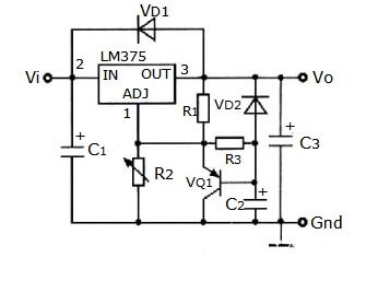
(3) Constant Current Source Circuit
To achieve high current stability, most modern drive circuits employ negative feedback control with multiple error amplification stages. The constant current control principle utilizes a closed-loop servo system that continuously monitors and adjusts the output current.
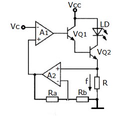
Closed-loop constant current control topology
The current regulation circuit consists of four functional blocks:
Reference Voltage Circuit: Provides the setpoint voltage proportional to desired current
Voltage-to-Current Conversion: Translates the reference voltage into the corresponding drive current
Constant Current Output Stage: Delivers the regulated current to the laser diode
Feedback Circuit: Senses actual current and closes the control loop
During operation, the reference voltage is appropriately scaled and applied to the non-inverting terminal of operational amplifier A1. This amplifier controls the base current of pass transistor VQ1 to produce the desired output current. The current flows through precision sampling resistor R, generating a proportional voltage that is amplified by A2 and fed back to the inverting input of A1.
The error amplifier A1 compares the feedback signal with the reference, adjusting the VQ1 base drive to maintain the output current at the setpoint. This closed-loop feedback system achieves dynamic equilibrium, stabilizing the output current against variations in supply voltage, temperature, and laser forward voltage.
Performance Enhancements: Modern constant current sources achieve regulation better than 0.01% and current noise below 0.5 μA RMS. Advanced designs incorporate:
Multi-stage error amplification for higher loop gain
Composite transistor output stages for improved current capability
Active filtering to reduce high-frequency noise
Temperature-compensated feedback networks
Digitally programmable current setpoints via DACs
(4) Protection Circuits
Comprehensive protection is essential because laser diodes are vulnerable to multiple failure modes:
Electrostatic Discharge (ESD) Protection: TVS diodes and series resistors limit transient voltages below 5V
Overcurrent Protection: Current limiting circuits prevent exceeding maximum ratings
Slow Start: Gradual current ramp-up (typically 1-10 ms) prevents turn-on stress
Thermal Shutdown: Temperature sensors disable drive if excessive heating occurs
Reverse Voltage Protection: Prevents reverse bias exceeding 2-3V
Open/Short Detection: Monitors laser connection and disables output on fault
3. Simple Transistor-Based Driving Circuit
For non-critical applications or low-cost designs, a basic common-emitter transistor circuit can provide adequate drive capability. While lacking the precision of feedback-controlled designs, this topology is suitable for LED applications, low-power laser pointers, and non-stabilized light sources.

Simple common-emitter transistor drive circuit
Operation is straightforward:
When Vi = 0 (logic low): Transistor BG is cut off, no current flows through the laser diode, producing no light output (representing binary "0")
When Vi = 1 (logic high): Transistor BG saturates, allowing current (typically 30-100 mA depending on application) to flow through the laser diode, producing light output (representing binary "1")
This digital modulation converts electrical signals into optical pulses, accomplishing intensity modulation. The current magnitude is primarily determined by the supply voltage and series resistor value according to Ohm's law, with the transistor saturation voltage (typically 0.2-0.3V) subtracted.
Limitations of Simple Circuits: This basic topology has several drawbacks:
No current regulation - output varies with supply voltage and temperature
No protection against transients or ESD
Switching transients can damage sensitive laser diodes
Temperature-dependent output power
Not suitable for analog modulation or precision applications
For professional applications, feedback-controlled designs are strongly recommended.
Modern Digital Drive Approaches
Contemporary laser modulation systems for high-speed digital communications (10 Gbps and beyond) use specialized techniques:
Direct Modulation: Fast switching of laser current for data rates up to 25 Gbps
Pre-distortion: Compensation for laser non-linearity and frequency chirp
Bias-and-Modulation: Separate DC bias (above threshold) plus AC modulation current
Driver IC Integration: Purpose-built ICs combine limiting amplifiers, current sources, and pre-emphasis
VII. Best Practices for Laser Diode Circuit Design (2025)
1. PCB Layout Considerations
Minimize inductance: Keep laser connections short with wide, heavy traces (minimum 50 mils width for 100 mA)
Ground plane: Use solid ground plane immediately adjacent to signal layer
Bypass capacitors: Place 0.1 μF ceramic and 10 μF tantalum capacitors close to laser power pins
Thermal management: Provide thermal vias under laser mounting area to heat sink on PCB backside
ESD protection: Route ESD protection devices (TVS diodes) as close as possible to laser pins
2. Modulation Techniques
Direct modulation: Suitable for data rates up to 25 Gbps; simple but causes frequency chirp
External modulation: Required for coherent systems and rates above 25 Gbps; uses CW laser with external modulator
Pre-emphasis: Boost high-frequency components to compensate for laser bandwidth limitations
Bias-and-modulation: Maintain DC bias above threshold, add AC modulation on top
3. Emerging Technologies
Recent developments in laser diode technology include:
Silicon photonics integration: Lasers integrated with silicon waveguides for on-chip optical interconnects
Quantum dot lasers: Lower threshold current, reduced temperature sensitivity
Mode-locked lasers: Generate ultra-short optical pulses for frequency comb applications
Vertical-cavity surface-emitting lasers (VCSELs): Dominate short-reach optical links (850 nm, 940 nm)
High-power diode bars: Multi-emitter arrays delivering hundreds of watts for industrial applications
Conclusion
This comprehensive guide has explored laser diode parameters, operating principles, luminescence theory, physical structure, testing methods, safety precautions, and multiple drive circuit topologies. Proper circuit design is essential for achieving reliable performance and maximizing laser diode lifetime.
Key takeaways include:
Laser diodes require precision constant-current drive with minimal noise and ripple
Automatic power control (APC) maintains stable optical output despite temperature and aging effects
Temperature control is critical for wavelength-stabilized applications
Comprehensive protection against ESD, overcurrent, and thermal stress prevents catastrophic failure
Modern applications demand integrated driver solutions with digital control interfaces
As laser technology continues advancing into 2025 and beyond, integrated photonics, quantum dot structures, and silicon photonics will enable new applications in quantum computing, LiDAR, biomedical imaging, and ultra-high-speed optical communications. Understanding fundamental drive circuit principles remains essential for successful implementation of these emerging technologies.
Further Resources:
For detailed specifications and application notes, consult manufacturers such as Thorlabs, Coherent (now part of II-VI), Lumentum, TRUMPF, and nLIGHT. IEEE Photonics Society and SPIE publish extensive research on laser diode technology and applications.
 UTMEL
UTMEL
We are the professional distributor of electronic components, providing a large variety of products to save you a lot of time, effort, and cost with our efficient self-customized service. careful order preparation fast delivery service
1.What is a laser diode used for?
Laser diodes are the most common type of lasers produced, with a wide range of uses that include fiber optic communications, barcode readers, laser pointers, CD/DVD/Blu-ray disc reading/recording, laser printing, laser scanning and light beam illumination.
2.How does a laser diode work?
A laser diode is an optoelectronic device, which converts electrical energy into light energy to produce high-intensity coherent light. In a laser diode, the p-n junction of the semiconductor diode acts as the laser medium or active medium.
3.What are the types of laser diodes?
There are several types of laser diodes:
Multi-longitudinal mode (MLM) or Fabry-Perot laser.
Single longitudinal mode laser (SLM)
Single longitudinal mode with distributed feedback laser, usually called a DFB laser.
DFB laser with external modulator.
Vertical-cavity surface-emitting laser (VCSEL)
4.How much does a laser diode cost?
The prices of some instruments can be as low as 6000 USD or less, while the newest, high-tier systems may cost as much as 70 000 USD.
5.Is diode laser permanent?
Diode lasers use a single wavelength of light that has a high abruption rate in melanin. As the melanin heats up it destroys the root and blood flow to the follicle disabling the hair growth permanently. ... Diode lasers deliver high frequency, low fluence pulses and can be safely used on all skin types.
 All You Need to Know About Rectifier CircuitUTMEL24 April 202517599
All You Need to Know About Rectifier Circuit
Read More 15 Key Elements of Diode SelectionUTMEL26 November 202118895
Hello everyone, I am Rose. Welcome back to the new post today. Diodes are one of the most common components in our circuit boards. So, what factors should be considered when selecting models?
Read More What is a PIN Diode?UTMEL04 February 202110220
While diodes with a simple PN junction are by far the most common type of diode in operation, in a variety of applications, other forms of diode may be used. The PIN diode is one type that is used for a number of circuits. In a variety of places, this diode type is used. For RF switching, the PIN diode is very fine, and the PIN structure in photodiodes is very useful as well.
Read More Microwave Diode: Introduction and TypesUTMEL07 January 202126011
Microwave diodes are diodes that work in the microwave frequency band. It is a solid-state microwave device. Microwave band usually refers to the frequency from 300 MHz to 3000 GHz. After the discovery of the point contact diode effect at the end of the 19th century, microwave diodes such as PIN diodes, varactor diodes, and Schottky diode tubes appeared one after another. Microwave diodes have the advantages of small size and high reliability, and are used in microwave oscillation, amplification, frequency conversion, switching, phase shifting and modulation.
Read More What Determines the Maximum Operating Frequency of a Diode?UTMEL29 June 202212918
Hello, wish you a wonderful day. In this essay, we first pose the following query: what determines the diode's maximum operating frequency? In regards to the solution, the first thing we need to understand is that the junction capacitance and the reverse recovery time of the diode are two distinct concepts. The charging and discharging times of the junction capacitance cannot match the reverse recovery time. You say that, why? Let's start by taking a look at these facts.
Read More
Subscribe to Utmel !
![MMZ2012S301AT000]() MMZ2012S301AT000
MMZ2012S301AT000TDK Corporation
![HI1806T600R-10]() HI1806T600R-10
HI1806T600R-10Laird-Signal Integrity Products
![BLM31KN102SH1L]() BLM31KN102SH1L
BLM31KN102SH1LMurata Electronics
![FBMH3225HM601NT]() FBMH3225HM601NT
FBMH3225HM601NTTaiyo Yuden
![BLM18PG330SH1D]() BLM18PG330SH1D
BLM18PG330SH1DMurata Electronics
![MMZ2012R600ATD25]() MMZ2012R600ATD25
MMZ2012R600ATD25TDK Corporation
![742792022]() 742792022
742792022Würth Elektronik
![BLM31PG330SH1L]() BLM31PG330SH1L
BLM31PG330SH1LMurata Electronics
![BK2125HS470-T]() BK2125HS470-T
BK2125HS470-TTaiyo Yuden
![MMZ1608B301CTAH0]() MMZ1608B301CTAH0
MMZ1608B301CTAH0TDK Corporation


