
 Product
 Brand
Brand Articles
 Tools
Tools
Introduction to Types of Diodes

What is a Diode?
Catalog
| |
I Types of diodes
There are many types of diodes: according to materials, there are germanium diodes, silicon diodes, gallium arsenide diodes, silicon carbide (SiC) diodes, and gallium nitride (GaN) diodes; they can be divided into surface contact diodes and point contact diodes according to the production process; according to different purposes, they can be divided into rectifier diodes, detection diodes, Zener diodes, varactor diodes, photodiodes, light-emitting diodes, switching diodes, fast recovery diodes, etc.; according to the type of connection, they can also be divided into semiconductor junction diodes, metal-semiconductor contact diodes (Schottky diodes), etc.; according to the package form, they can be divided into conventional packaged diodes, special packaged diodes, surface-mount diodes (SMD), etc. The following introduces the characteristics of different types of diodes according to different purposes.
1. Rectifier diode
The role of the rectifier diode is to rectify AC power into pulsating DC power. It works by using the unidirectional conductive characteristics of the diode. Because the forward working current of the rectifier diode is large, the surface contact structure is mostly used in the process. The junction capacitance of this structure is relatively large, so the operating frequency of the rectifier diode is generally less than 3 kHz for standard silicon rectifier diodes, though modern fast recovery rectifier diodes can operate at significantly higher frequencies.
Rectifier diodes are mainly available in hermetically sealed metal structure packages and plastic packages. Under normal circumstances, the rectifier diode with a rated forward current IF above 1 A is packaged in a metal case to facilitate heat dissipation; the rated forward operating current less than 1 A is typically in an all-plastic package. Additionally, due to the continuous improvement of packaging technology, there are now many high-power rectifier diodes in plastic packages with enhanced thermal management capabilities, which should be distinguished in use.

Figure 1 bridge rectifier circuit
Because the rectifier circuit is usually a bridge rectifier circuit (as shown in Figure 1), some manufacturers package four rectifier diodes together. Such integrated components are often called rectifier bridges or rectifier full bridges. The shape of a common rectifier diode is shown in Figure 2.

Figure 2 rectifier diode
When selecting a rectifier diode, parameters such as maximum rectification current, maximum reverse voltage, cutoff frequency, and reverse recovery time should be considered. The rectifier diodes used in ordinary series regulated power supply circuits do not have high requirements on the reverse recovery time or cutoff frequency. As long as the maximum rectification current and the maximum reverse working voltage meet the requirements, standard rectifier diodes (such as the 1N400x series, 2CZ series, RLR series, etc.) can be selected. Rectifier diodes used in switching regulated power supplies and high-frequency pulse rectifier circuits should use rectifier diodes with higher operating frequencies and shorter reverse recovery times, such as fast recovery diodes or ultra-fast recovery diodes.
2. Detection diode
A detection diode is a device that detects low-frequency signals superimposed on a high-frequency carrier wave, which has high detection efficiency and good frequency characteristics. Detection diodes are primarily used in demodulation circuits for AM radio receivers and signal processing applications.

Figure 3 detection diode
Detector diodes require small forward voltage drop, high detection efficiency, small junction capacitance, and good frequency characteristics. The shape of the detector diode is generally a glass package structure. General detection diodes use a germanium material point contact type structure, though modern silicon detector diodes are also available with improved temperature stability.
When selecting a detection diode, a detection diode with a high operating frequency, a small reverse current, and a sufficiently large forward current should be selected according to the specific requirements of the circuit.
3. Switching diode
A switching diode is a kind of semiconductor diode, which is specially designed and manufactured for "on" and "off" operations in circuits. The time required for it to change from on to off or from off to on is shorter than that of ordinary diodes. Common series include 2AK, 2DK, 1N4148, and others, which are mainly used in electronic computers, pulse circuits, and switching circuits. Switching diodes are extensively used in consumer electronics such as smartphones, tablets, computers, televisions, and professional equipment, including switching circuits, detection circuits, high-frequency pulse rectifier circuits, and digital logic circuits.

Figure 4 Switching diode
The semiconductor diode is equivalent to a closed switch (the circuit is on) when conducting, and equivalent to an open circuit (the circuit is off) when non-conducting, so the diode can be used as a switch. The commonly used model is 1N4148, which features a fast switching speed (reverse recovery time of approximately 4 nanoseconds) and a maximum reverse voltage of 100V. Because the semiconductor diode has the characteristic of unidirectional conduction, the PN junction is turned on under forward bias, and the on-state resistance is very small, about tens to several hundred ohms; under reverse bias, it is turned off, and its resistance is very large. Generally, silicon diodes have reverse resistance above 10 megaohms, and germanium tubes also have tens of thousands of ohms to hundreds of thousands of ohms. With this feature, the diode plays a role in controlling current on or off in the circuit and becomes an ideal electronic switch.
For medium-speed switching circuits and detection circuits, 2AK series ordinary switching diodes can be selected. High-speed switching circuits can choose RLS series, 1SS series, 1N series, 2CK series high-speed switching diodes. The specific model of the switching diode should be chosen according to the main parameters of the application circuit (such as forward current, maximum reverse voltage, reverse recovery time, etc.)
4. Zener diode
Zener diode uses the characteristic that the voltage remains relatively constant when the PN junction undergoes reverse breakdown, maintaining stable voltage despite changes in current, to achieve voltage regulation. The Zener diode is categorized according to the breakdown voltage, and its voltage regulation value corresponds to the breakdown voltage value. Zener diodes are mainly used as voltage regulators or voltage reference components in power supplies, voltage monitoring circuits, and precision analog circuits. Zener diodes can be connected in series to obtain higher voltage values, or used individually for precise voltage reference applications.

Figure 5 Zener diode
The selected Zener diode should meet the requirements of the main parameters in the corresponding circuit. The stable voltage value of the Zener diode should match the reference voltage value of the application circuit. The maximum stable current of the Zener diode should be approximately 50% higher than the maximum load current of the application circuit to ensure reliable operation and adequate margin.
5. Fast Recovery Diode (FRD)
Fast Recovery Diode is a semiconductor diode with good switching characteristics and a short reverse recovery time. It is commonly used as a rectifier diode in high-frequency switching power supplies, inverters, motor drives, and power factor correction (PFC) circuits. The fast recovery diode is characterized by its short recovery time, which makes it suitable for high-frequency (such as tens to hundreds of kHz) rectification applications. The fast recovery diode has an important parameter that determines its performance—reverse recovery time (trr). The definition of the reverse recovery time is the duration from when the diode transitions sharply from the forward conducting state to the off state, starting from when the current crosses zero until it stabilizes at the blocking state.
Ultra-fast recovery diodes (URDs or SRDs) are developed based on fast recovery diodes. The main difference between them is that the reverse recovery time is even shorter. The reverse recovery time of a common fast recovery diode is several hundred nanoseconds (typically 200-500 ns), while the reverse recovery time of an ultra-fast recovery diode (URD/SRD) is generally tens of nanoseconds (typically 20-100 ns). The smaller the value, the higher the operating frequency capability of the fast recovery diode and the lower the switching losses.

Figure 6 Fast Recovery Diode
When the operating frequency is in the range of tens to hundreds of kHz, the transition time between forward and reverse voltage states of ordinary rectifier diodes is slower than required, and ordinary rectifier diodes cannot work properly in unidirectional conduction at these frequencies. However, fast recovery rectifier diodes are well-suited for these applications. Therefore, rectifier diodes in switching power supplies for modern electronics such as LCD/LED TVs, computers, and other consumer appliances are usually fast recovery diodes and cannot be replaced by ordinary rectifier diodes. Otherwise, electrical appliances may not work properly or may experience reduced efficiency and increased heat generation. The shape of a common fast recovery diode is shown in Figure 6.
6. Schottky diode (SBD)
Schottky diode is an abbreviation of the Schottky Barrier Diode (SBD). Schottky diodes are low-power-loss, high-current, ultra-high-speed semiconductor devices. Its reverse recovery time is extremely short (it can be as small as a few nanoseconds or even sub-nanosecond range), the forward voltage drop is only about 0.3-0.5V (compared to 0.6-0.7V for standard silicon diodes), and the rectified current capability can reach several hundred amps in power applications. These excellent characteristics make Schottky diodes superior to fast recovery diodes in many high-frequency, high-efficiency applications.
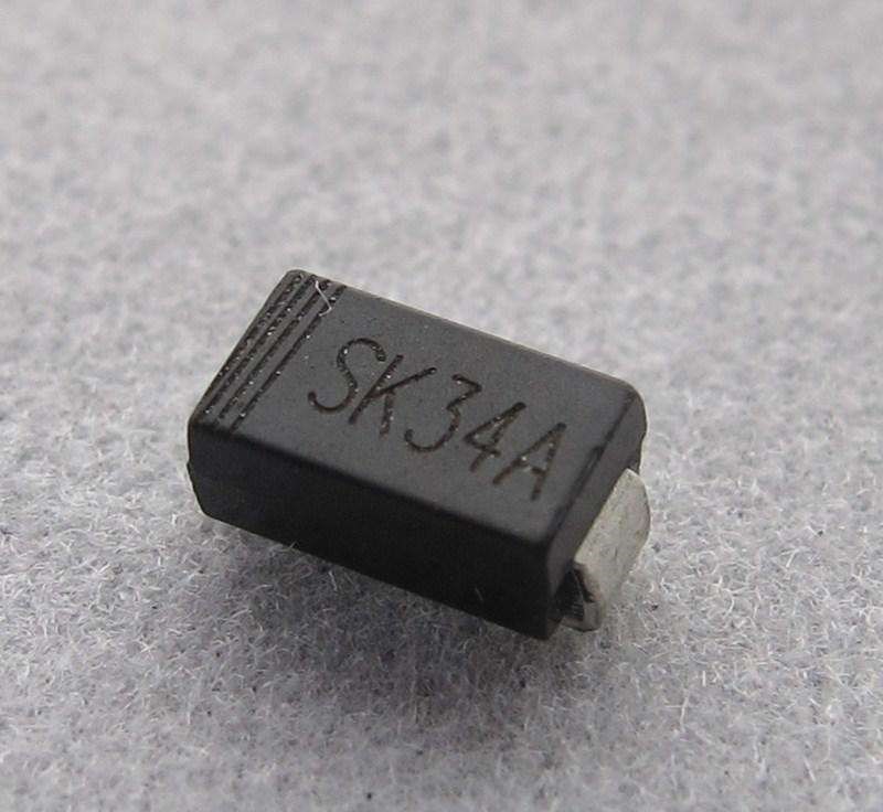
Figure 7 Schottky diode
Schottky diodes are metal-semiconductor devices made with precious metals (gold, silver, aluminum, platinum, etc.) or refractory metals as the positive electrode and N-type semiconductors as the negative electrode, forming a metal-semiconductor junction rather than a PN junction. Schottky diodes are commonly used in high-frequency, high-current, low-voltage rectifier circuits, including switch-mode power supplies, solar inverters, automotive electronics, and modern USB-C fast charging applications with Power Delivery (PD) protocols. Modern applications also include synchronous rectification in DC-DC converters and OR-ing circuits in redundant power systems. The appearance of a common Schottky diode is shown in Figure 7.
7. Transient voltage suppression diode
The transient voltage suppression diode is referred to as a TVS diode (Transient Voltage Suppressor). It is a semiconductor device developed based on voltage regulator tube technology and is mainly used in fast overvoltage protection circuits. It can be widely used in computers, smartphones, tablets, communication equipment, household appliances, automotive electronics, industrial control systems, and field-borne/marine electronic equipment. Modern TVS diodes are essential in protecting sensitive electronics from electrostatic discharge (ESD), lightning-induced surges, and load dump transients. They can also be used as protective elements for overvoltage impacts caused by human operation or electrical surges to equipment.
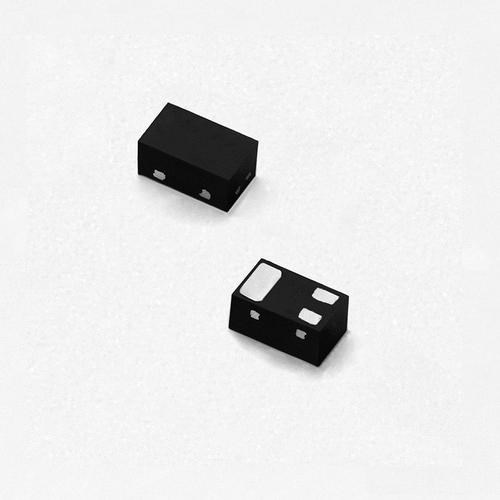
Figure 8 transient voltage suppression diode
Transient voltage suppression diodes can be divided into multiple categories according to their peak pulse power ratings: 400W, 500W, 600W, 1000W, 1500W, 3000W, 5000W, and even higher power ratings for industrial and automotive applications. Each category is divided into several types according to nominal voltage ratings (typically ranging from 5V to over 500V). When the voltage at both ends of the transient voltage suppression diode exceeds the rated breakdown voltage, it will be turned on instantaneously (typically within 1 picosecond response time) and clamp the voltage to a predetermined safe level, protecting downstream circuits. The shape of the transient voltage suppression diode is shown in Figure 8.
8. LED
The abbreviation of the light-emitting diode is LED, which is a device made of semiconductor materials such as gallium phosphide (GaP), gallium arsenide phosphide (GaAsP), gallium nitride (GaN), indium gallium nitride (InGaN), and aluminum gallium indium phosphide (AlGaInP), which can directly convert electrical energy into light energy. In addition to the unidirectional conductivity of ordinary diodes, light-emitting diodes can also convert electrical energy into light energy through electroluminescence. When a forward voltage is applied to the light-emitting diode and forward current flows through the die, the light-emitting diode emits light, converting electrical energy into photons.
The color of the light-emitting diode is mainly determined by the material of the semiconductor and the type of impurities (dopants). Currently, common light-emitting diodes are available in blue, green, yellow, red, orange, white, and specialized colors such as UV and infrared. White light-emitting diodes are typically created using blue LED chips with yellow phosphor coating, or by combining red, green, and blue (RGB) LED chips. Modern white LEDs are extensively used in mobile phone backlights, LCD/OLED display backlights, automotive lighting, general illumination, and specialty lighting applications. The working current of light-emitting diodes is usually 2 to 25 mA for indicator LEDs, while high-power LEDs used in lighting applications can operate at currents from 350 mA to several amperes. The working voltage (forward voltage drop) varies with different materials: ordinary green, yellow, red, and orange light-emitting diodes have a working voltage of about 1.8-2.2V; white light-emitting diodes typically have a working voltage of 2.8-3.6V; blue light-emitting diodes typically have a working voltage of 3.0-3.6V; and UV LEDs can have forward voltages exceeding 3.6V. The working current of the LED must not exceed the rated value, otherwise, there is a risk of damage or significantly reduced lifespan. Therefore, a resistor or constant-current driver circuit is usually used in LED circuits as a current limiting element.
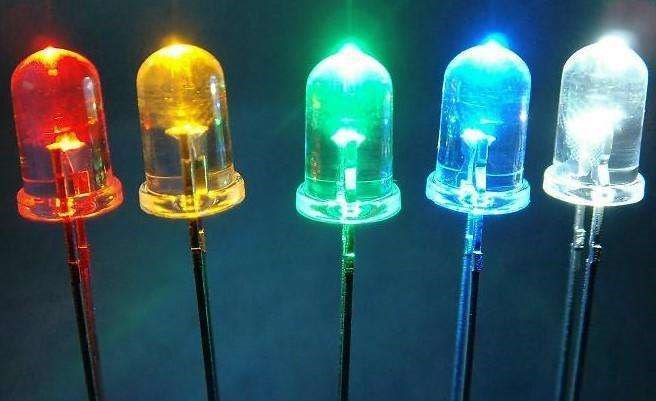
Figure 9 LED
An infrared light-emitting diode (IR LED) is a special kind of light-emitting diode. Its appearance is similar to visible light-emitting diodes, but it emits infrared light (wavelengths typically 850 nm, 940 nm, or longer), which is invisible to the human eye. Its working voltage is typically about 1.2-1.4V, and the working current is generally less than 20 mA for indicator applications, though high-power IR LEDs for communication and sensing can operate at much higher currents. IR LEDs are widely used in remote controls, optical communication, proximity sensors, night vision cameras, and security systems. Some manufacturers package two light-emitting diodes of different colors together to make bi-color diodes (also known as color-changing light-emitting diodes or dual-color LEDs). This light-emitting diode usually has three pins, one of which is a common terminal (either common anode or common cathode). It can emit three colors of light (one of which is a mixture of two colors when both are illuminated simultaneously), so it is usually used as an indicator for different working states in electronic equipment. RGB LEDs with separate red, green, and blue chips can produce a full spectrum of colors. The shape of common light-emitting diodes is shown in Figure 9.
9. Avalanche Diode
The avalanche diode is a microwave power device developed based on voltage regulator tube technology. It can generate high-frequency oscillation under the action of an applied voltage, making it suitable for microwave signal generation and amplification.
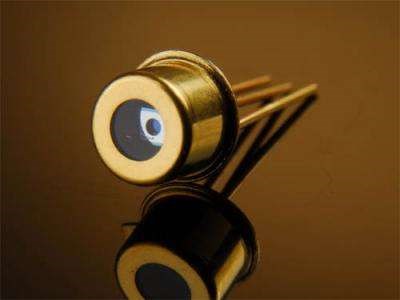
Figure 10 avalanche diode
Avalanche diodes utilize avalanche breakdown to inject carriers into the crystal. Because carriers take a finite amount of time to transit across a semiconductor wafer, their current response lags behind the voltage, creating a phase delay. This results in a negative resistance effect in the current-voltage relationship, which enables high-frequency oscillation. Avalanche diodes are often used in microwave communication systems, radar applications, tactical missile guidance, remote control, telemetry, instrumentation, signal generators, and other specialized equipment operating in the GHz frequency range.
10. DIAC
The DIAC (diode for alternating current) is a bidirectional trigger diode that conducts electrical current only after its breakover voltage (VBO) has been reached momentarily in either polarity. DIACs are also called symmetrical trigger diodes. It is a silicon bidirectional voltage-triggered switching device. When the voltage applied across the symmetrical trigger diode exceeds its breakdown voltage (typically 28-36V), both ends conduct, and the conduction will continue until the current is interrupted or decreases below the minimum holding current of the device, at which point it turns off again. Symmetrical trigger diodes are commonly used in overvoltage protection circuits, phase shift circuits, thyristor (SCR and TRIAC) trigger circuits, dimmer controls, motor speed controls, and timing circuits.
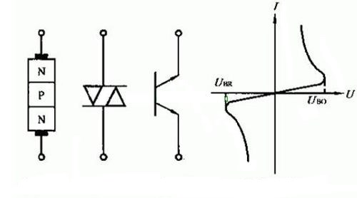
Figure 11 diode for alternating current
11. Varactor diode
A varactor diode or variable capacitance diode (abbreviated as VCD) is a special semiconductor device that uses reverse bias to change the capacitance of a PN junction. A varactor diode is equivalent to a voltage-controlled variable capacitor. The capacitance of the PN junction between its two electrodes changes with the magnitude of the reverse voltage applied across the varactor diode. When the reverse voltage applied across the varactor diode increases, the depletion region widens and the capacitance of the varactor diode decreases. Conversely, when the reverse voltage decreases, the capacitance increases. Because the varactor diode has this voltage-dependent capacitance characteristic, it is mainly used in electronically-tuned circuits (such as high-frequency tuners in televisions and radios, voltage-controlled oscillators (VCOs), frequency synthesizers, phase-locked loops (PLLs), and RF communications equipment) as an automatic trimming capacitor that can be controlled by voltage.
Figure 12 varactor diode
When selecting a varactor diode, it is important to consider whether its operating frequency range, maximum reverse working voltage, maximum forward current, zero-bias junction capacitance, capacitance ratio (the ratio of capacitance at minimum voltage to capacitance at maximum voltage), and Q-factor (quality factor) meet the requirements of the application circuit.
12. Silicon Carbide (SiC) diodes
Silicon Carbide (SiC) diodes represent a significant advancement in power semiconductor technology. SiC is a wide bandgap semiconductor material (bandgap ~3.26 eV compared to silicon's ~1.12 eV) that offers superior performance in high-voltage, high-temperature, and high-frequency applications. SiC diodes, particularly SiC Schottky diodes, have become increasingly important since the early 2010s and have seen widespread adoption in the 2020s.
Key advantages of SiC diodes:
Zero reverse recovery: SiC Schottky diodes have virtually no reverse recovery charge, eliminating switching losses associated with reverse recovery.
High voltage capability: Can operate at voltages from 600V to 1700V and beyond, with recent developments reaching 2000V ratings.
High temperature operation: Can operate reliably at junction temperatures up to 175°C or higher, compared to 150°C for silicon devices.
Higher efficiency: Lower conduction losses and switching losses result in overall system efficiency improvements of 2-5%.
Higher switching frequency: Enables operation at frequencies exceeding 100 kHz, allowing for smaller passive components and more compact system designs.
Applications: SiC diodes are widely used in electric vehicle (EV) powertrains and onboard chargers, solar inverters and energy storage systems, industrial motor drives, server and data center power supplies (including emerging 800V DC infrastructure), traction systems, and aerospace applications. The SiC power device market is projected to grow significantly, with estimates suggesting growth from approximately $1 billion in 2023-2024 to over $6-8 billion by 2030.
13. Gallium Nitride (GaN) diodes
Gallium Nitride (GaN) diodes are another type of wide bandgap semiconductor device (bandgap ~3.4 eV) that has gained significant traction since 2015, with explosive growth in consumer and industrial applications from 2020 onward. While GaN is more commonly known for transistor applications (GaN HEMTs), GaN-based diodes also offer unique advantages.
Key characteristics of GaN technology:
Ultra-fast switching: Switching times in the sub-nanosecond range, enabling very high frequency operation (MHz range).
Low on-resistance: Extremely low conduction losses in the on-state.
High power density: Allows for very compact power converter designs.
Excellent efficiency: Power conversion efficiencies exceeding 95-98% are common.
Comparison with SiC: GaN typically operates at lower voltages (30V-650V) compared to SiC, making it ideal for consumer electronics and lower-voltage industrial applications. GaN offers higher switching frequencies than SiC, while SiC has better thermal conductivity and is preferred for higher voltage (>900V) and higher power applications. The choice between GaN and SiC depends on the specific application requirements.
Applications: GaN technology is extensively used in USB-C PD fast chargers (enabling chargers 3-4x smaller than traditional silicon-based chargers), laptop and smartphone adapters, wireless charging, consumer power supplies, server power supplies and data center infrastructure, 5G telecommunications base stations, LiDAR systems, RF power amplifiers, and automotive 48V systems. The market for GaN power devices is growing rapidly, with the combined GaN and SiC market projected to exceed $10 billion by 2030.
II Identification and detection of diodes
1. Identification of the diode
Crystal diodes are usually represented by VD or D plus numbers in circuit diagrams, such as VD5 or D5 indicates the diode numbered 5. In international standard circuits, the symbols of commonly used diodes are shown in Figure 13.
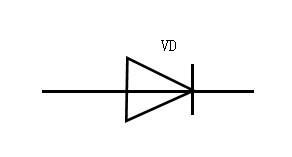
Figure 13 symbols of diode
The identification of a diode polarity is straightforward: the cathode (negative pole) of a low-power diode is usually marked with a color ring or band on the package surface; some diodes also use the "A" and "K" symbols to determine the polarity of the diode, where "A" represents the anode (positive) and "K" represents the cathode (negative). Some older devices may use "P" for positive and "N" for negative. Metal-packaged diodes typically have a diode symbol printed on the surface indicating polarity; light-emitting diodes usually use lead length to identify the positive and negative poles, with the longer lead being positive (anode) and the shorter lead being negative (cathode). Additionally, when viewing an LED from the side through the clear epoxy, the larger internal element (the anvil/reflector cup) is typically connected to the cathode, while the smaller element (the post) connects to the anode.
The surface of the rectifier bridge is usually marked with the internal circuit structure or the designations of the AC input terminals and the DC output terminals. The AC input terminals are usually represented by "AC" or "~" symbols; the DC output terminals are usually represented by "+" and "-" symbols indicating positive and negative polarity.
Surface-mount diodes (SMD diodes) have various package forms, and their polarities are marked in multiple ways: in leaded chip diodes, the end with a white or colored band is the cathode; in leadless chip diodes without color bands, the end with a printed line, notch, or chamfered edge typically indicates the cathode; some SMD packages have a printed symbol or letter indicating polarity.
2. Diode detection
When using a pointer-type (analog) multimeter to detect a diode, note that the internal battery polarity is opposite to the test lead markings: the black test lead connects to the positive terminal of the internal battery. When the black test lead connects to the diode's anode and the red test lead to the cathode, the diode is forward biased and will show a low resistance reading. To test forward resistance, set the multimeter to a low resistance range (typically R×100 or R×1k), connect the black lead to the anode and red lead to the cathode. The meter should show a relatively low resistance. Then reverse the connections to measure reverse resistance, which should be very high. If both forward and reverse resistances are infinite (open circuit), the diode is open/damaged; if both forward and reverse resistances are near zero, the diode is short-circuited and damaged. Under normal circumstances, the forward resistance of a germanium diode is approximately 300Ω to 1.6kΩ (depending on the ohm range used), while silicon diodes typically show 5kΩ to 10kΩ or higher on the R×1k range.
When using a digital multimeter to measure a diode, the red test lead connects to the positive pole of the diode, and the black test lead connects to the negative pole of the diode. At this time, the measured value is the forward voltage drop of the diode, which provides a more precise indication of diode condition than resistance measurement.
Using the digital multimeter's dedicated diode test mode is the most convenient method. Set the digital multimeter to the diode test position (usually marked with a diode symbol), then connect the cathode (negative pole) of the diode to the black lead of the digital multimeter, and the anode (positive pole) to the red lead. For different diode materials, typical forward voltage drop values are: 0.55 to 0.7V for silicon diodes, 0.15 to 0.35V for germanium diodes, and 0.3 to 0.5V for Schottky diodes. If the display shows "0.000" or a very low value, it indicates the tube is short-circuited; if it shows "OL" (overload), "1" or similar overrange indication in forward bias, it means the diode is internally open or you have the connections reversed. Always test in both directions to confirm proper unidirectional conduction behavior.
III Main parameters of diodes
Different types of diodes have different characteristics and parameters. For engineers and electronics enthusiasts, understanding the following main parameters is essential:
1. Rated forward working current (IF)
The rated forward working current (IF) refers to the maximum forward current value allowed by the diode during continuous long-term operation under specified conditions (typically at 25°C ambient temperature). Because when current passes through the diode, the junction will be heated and temperature will rise. If temperature exceeds the allowable limit (silicon junction temperature limit is approximately 150-175°C and germanium junction temperature limit is approximately 90-100°C), the PN junction will be damaged and the diode will fail. Therefore, do not exceed the rated forward working current of the diode during use. For example, the commonly used 1N4001 silicon diode has a rated forward operating current of 1A, while the 1N4007 (same current rating but higher voltage rating) also has IF = 1A. High-power rectifier diodes can have ratings from several amperes to hundreds of amperes.
2. Maximum surge current (IFSM)
The maximum surge current (IFSM) is the maximum instantaneous forward current allowed to flow through the diode for a very brief period (typically specified for 8.3ms for a half-cycle of 60Hz or 10ms for 50Hz). This is not a continuous operating current, but rather a short-duration peak current that the device can withstand without damage. This value is usually about 10 to 30 times the rated forward working current. For example, a diode with IF = 1A might have IFSM = 30A. This parameter is important for applications where inrush currents occur, such as power supply turn-on or capacitor charging.
3. Maximum reverse working voltage (VR or VRRM)
When the reverse voltage applied across the terminals of the diode reaches a certain value, the diode will experience avalanche breakdown and lose its unidirectional conductivity, potentially causing permanent damage. To ensure safe and reliable operation, the maximum reverse working voltage (VR or VRRM) is specified. This is the maximum reverse voltage that can be continuously applied to the diode without causing breakdown. For safety and reliability, designs typically operate at 50-80% of the maximum reverse voltage rating. For example, the reverse withstand voltage of the 1N4001 diode is 50V, 1N4004 is 400V, and 1N4007 is 1000V. Modern power diodes are available with reverse voltage ratings from tens of volts to several thousand volts (e.g., SiC diodes rated at 1200V, 1700V, or higher).
4. Reverse leakage current (IR)
Reverse leakage current (IR) refers to the small current that flows through the diode when a specified reverse voltage is applied, measured at a specified temperature (typically 25°C or the maximum rated junction temperature). The smaller the reverse current, the better the unidirectional conductivity and quality of the diode. It is important to note that reverse current has a strong relationship with temperature. For silicon diodes, the reverse current approximately doubles for every 10°C increase in temperature. For example, a silicon diode with IR = 5μA at 25°C might have IR = 10μA at 35°C, IR = 20μA at 45°C, and so on. At 75°C, the reverse current could increase to 160μA or more. Germanium diodes are even more temperature-sensitive. For example, a 2AP1 germanium diode at 25°C has a reverse current of approximately 250μA; when temperature rises to 35°C, the reverse current will rise to 500μA or more; and at 75°C, its reverse current can reach 8mA or higher, at which point the diode's rectification performance significantly degrades and excessive heat may damage the device. Silicon diodes have much better temperature stability than germanium diodes, which is one reason silicon has become the dominant semiconductor material.
5. Reverse recovery time (trr)
When a diode switches from conducting forward current to the blocking state (from forward bias to reverse bias), it takes a finite amount of time for the stored charge carriers in the semiconductor to be removed. This time is called the reverse recovery time (trr). Ideally, when changing from forward voltage to reverse voltage, the current would be cut off instantaneously. However, in reality, there is always a delay. The reverse recovery time determines how quickly the diode can switch off, which directly affects the diode's maximum switching frequency and the switching losses in the circuit. Standard rectifier diodes have relatively long reverse recovery times (several microseconds), making them suitable only for low-frequency applications (50/60 Hz power line frequencies). Fast recovery diodes have trr in the range of 200-500 nanoseconds. Ultra-fast recovery diodes have trr in the range of 20-100 nanoseconds. Schottky diodes have negligible reverse recovery time (less than 10 nanoseconds, often sub-nanosecond), because they are majority carrier devices with no stored minority charge. While shorter reverse recovery time is generally desirable for high-frequency applications, it's not always the only consideration—other factors such as forward voltage drop, reverse leakage current, and voltage rating must also be balanced for the specific application.
6. Forward voltage drop (VF)
Forward voltage drop (VF) is the voltage that appears across the diode terminals when it is conducting forward current at a specified current level (typically at the rated IF). This represents the voltage "lost" across the diode and contributes to power dissipation and heat generation. Different diode types have characteristic forward voltage drops: Standard silicon diodes: 0.6-0.7V at rated current; Germanium diodes: 0.2-0.3V at rated current; Schottky diodes: 0.3-0.5V at rated current; SiC Schottky diodes: 1.2-1.5V at rated current (higher than silicon Schottky, but with other advantages); LEDs: 1.8-3.6V depending on color and material. Lower forward voltage drop is desirable as it reduces power loss and improves efficiency, especially in high-current applications.
7. Maximum power dissipation (PD or Ptot)
The maximum power dissipation (PD) is the maximum power that the diode can safely dissipate as heat under specified conditions, typically at 25°C ambient temperature with proper heat sinking if required. This limit parameter is calculated as the product of the voltage across the diode and the current flowing through it (P = V × I). This parameter is particularly important for Zener diodes, high-power rectifier diodes, and other diodes operating at significant power levels. The actual power dissipation must be kept below this limit to prevent junction temperature from exceeding safe limits. Adequate heat sinking must be provided for high-power applications. The maximum power dissipation decreases (must be derated) as ambient temperature increases or if heat sinking is inadequate. Manufacturers typically provide derating curves showing how much the power rating decreases with increasing temperature.
8. Junction capacitance (Cj)
Junction capacitance (Cj) is the capacitance that exists across the PN junction of the diode, measured under specified reverse bias conditions. This capacitance affects the high-frequency performance of the diode. For high-frequency and high-speed switching applications, low junction capacitance is desirable because high capacitance limits switching speed and causes additional losses at high frequencies. Junction capacitance varies with applied reverse voltage (increases as reverse voltage decreases). Varactor diodes intentionally exploit this voltage-dependent capacitance characteristic. Typical values range from a few picofarads (pF) for small-signal diodes to hundreds of picofarads for power diodes.
IV Modern applications and future trends
The field of diode technology continues to evolve rapidly, driven by demands for higher efficiency, greater power density, and improved performance across a wide range of applications.
Emerging applications
Electric vehicles and transportation: Wide bandgap semiconductors (SiC and GaN) are revolutionizing EV powertrains, enabling higher efficiency, reduced weight, and extended driving range. SiC diodes and MOSFETs are becoming standard in EV traction inverters, onboard chargers, and DC-DC converters, with major automotive manufacturers committing to SiC-based systems for their next-generation vehicles.
Renewable energy systems: Solar inverters and wind turbine converters increasingly rely on SiC diodes to achieve efficiencies exceeding 99%, reducing energy losses in renewable energy generation and storage systems. The improved thermal performance allows for more compact inverter designs suitable for residential and commercial installations.
Data centers and telecommunications: GaN-based power supplies are enabling the transition to 48V and 800V DC distribution systems in data centers, significantly improving power delivery efficiency. The combination of GaN and SiC technologies is crucial for 5G base stations, where high efficiency and compact size are essential.
Consumer electronics: GaN chargers have transformed the USB-C fast charging market, with chargers capable of delivering 65W, 100W, or even 140W+ in packages 50-70% smaller than traditional silicon-based chargers. Quantum dot LEDs (QLEDs) are advancing display technology with higher color gamut, better efficiency (external quantum efficiency now exceeding 20-26% for various colors), and improved lifetime.
Future development trends
Ultra-wide bandgap materials: Research is advancing on materials beyond SiC and GaN, including gallium oxide (Ga2O3), aluminum nitride (AlN), and diamond, which promise even higher voltage ratings, temperature tolerance, and efficiency for next-generation power electronics.
Integration and miniaturization: Continued integration of diodes with other power components in intelligent power modules (IPMs) and system-in-package (SiP) solutions will enable more compact and efficient power conversion systems.
Advanced LED technology: Micro-LED and quantum dot LED technologies are advancing toward commercialization, promising displays with unprecedented brightness, contrast, efficiency, and lifespan. Recent developments have achieved record external quantum efficiencies exceeding 40% for green micro-LEDs and 22% for red micro-LEDs.
Sustainability and manufacturing: The semiconductor industry is focusing on sustainable manufacturing processes for wide bandgap semiconductors, aiming to reduce energy consumption, material waste, and environmental impact while scaling production to meet growing demand.
The diode technology landscape continues to expand, with traditional silicon devices coexisting alongside advanced wide bandgap solutions, each optimized for specific applications and performance requirements.
Recommended Reading:
Schottky Diodes: Principle, Functions and Applications
Understanding Wide Bandgap Semiconductors
Article Update Information
Original Publication Date: 2020
Last Updated: October 2025
Updates and Corrections:
Corrected spelling error: "FR D" changed to "FRD" in section heading
Added two new sections on Silicon Carbide (SiC) diodes and Gallium Nitride (GaN) diodes to reflect major technological advances since 2020
Updated LED section with current information on quantum dot technology and efficiency improvements (EQE >20-40% for various colors as of 2024-2025)
Enhanced Schottky diode section with modern applications including USB-C Power Delivery and fast charging
Updated TVS diode section with expanded power ratings (up to 5000W) and modern application examples
Expanded technical specifications for various diode types with current industry standards
Added comprehensive section on modern applications and future trends
Updated temperature specifications for silicon devices (150-175°C junction temperature)
Corrected and expanded parameter definitions in Section III
Added practical testing guidance for digital multimeters
Expanded catalog to include new diode types (SiC and GaN)
Enhanced readability and technical accuracy throughout
Technical Accuracy: All specifications and parameters have been verified against current industry standards and manufacturer datasheets as of October 2025. Wide bandgap semiconductor market projections are based on industry analyst reports from 2024-2025.
 UTMEL
UTMEL
We are the professional distributor of electronic components, providing a large variety of products to save you a lot of time, effort, and cost with our efficient self-customized service. careful order preparation fast delivery service
1.What is a diode and its types?
A diode is a two-terminal electrical device, that allows the transfer of current in only one direction. Most of the diodes are made from semiconductors such as Si (silicon), but in a few cases, Ge (germanium) is also used. It is sometimes beneficial to summarize the different types of diodes are existing.
2.What is the most common diode?
1N4148 The most commonly used signal diode is the 1N4148. This diode has a close brother called 1N914 that can be used in its place if you can't find a 1N4148. This diode has a forward-voltage drop of 0.7 and a peak inverse voltage of 100 V, and can carry a maximum of 200 mA of current.
3.What is diode and its function?
A diode is a device that allows current to flow in one direction but not the other. This is achieved through a built-in electric field. (Bild: Public Domain) A diode is a device that allows current to flow in one direction but not the other. This is achieved through a built-in electric field.
4.What are special diodes?
There are few diodes which are designed to serve some special purposes. There are many of such kinds like Transient voltage suppression diodes, Gold doped diodes, Super barrier diodes, Point contact diodes, Peltier diodes etc.
5.How are diodes classified?
Diodes are classified according to their characteristics and are offered in a number of different types, including rectifiers, switching diodes, Schottky barrier diodes, Zener (constant voltage) diodes, and diodes designed for high-frequency applications.
 All You Need to Know About Rectifier CircuitUTMEL24 April 202517208
All You Need to Know About Rectifier Circuit
Read More 15 Key Elements of Diode SelectionUTMEL26 November 202118673
Hello everyone, I am Rose. Welcome back to the new post today. Diodes are one of the most common components in our circuit boards. So, what factors should be considered when selecting models?
Read More What is a PIN Diode?UTMEL04 February 20219885
While diodes with a simple PN junction are by far the most common type of diode in operation, in a variety of applications, other forms of diode may be used. The PIN diode is one type that is used for a number of circuits. In a variety of places, this diode type is used. For RF switching, the PIN diode is very fine, and the PIN structure in photodiodes is very useful as well.
Read More Microwave Diode: Introduction and TypesUTMEL07 January 202125171
Microwave diodes are diodes that work in the microwave frequency band. It is a solid-state microwave device. Microwave band usually refers to the frequency from 300 MHz to 3000 GHz. After the discovery of the point contact diode effect at the end of the 19th century, microwave diodes such as PIN diodes, varactor diodes, and Schottky diode tubes appeared one after another. Microwave diodes have the advantages of small size and high reliability, and are used in microwave oscillation, amplification, frequency conversion, switching, phase shifting and modulation.
Read More What Determines the Maximum Operating Frequency of a Diode?UTMEL29 June 202212620
Hello, wish you a wonderful day. In this essay, we first pose the following query: what determines the diode's maximum operating frequency? In regards to the solution, the first thing we need to understand is that the junction capacitance and the reverse recovery time of the diode are two distinct concepts. The charging and discharging times of the junction capacitance cannot match the reverse recovery time. You say that, why? Let's start by taking a look at these facts.
Read More
Subscribe to Utmel !
![ST1284-01A8RL]() ST1284-01A8RL
ST1284-01A8RLSTMicroelectronics
![MMZ2012R102AT000]() MMZ2012R102AT000
MMZ2012R102AT000TDK Corporation
![MMZ2012Y102BTD25]() MMZ2012Y102BTD25
MMZ2012Y102BTD25TDK Corporation
![BKP1005HS221-T]() BKP1005HS221-T
BKP1005HS221-TTaiyo Yuden
![BLM03BD241SN1D]() BLM03BD241SN1D
BLM03BD241SN1DMurata Electronics
![BLM18RK221SN1D]() BLM18RK221SN1D
BLM18RK221SN1DMurata Electronics
![MPZ1608S181ATAH0]() MPZ1608S181ATAH0
MPZ1608S181ATAH0TDK Corporation
![BLM03HG601SN1D]() BLM03HG601SN1D
BLM03HG601SN1DMurata Electronics
![BLM15AG221SH1D]() BLM15AG221SH1D
BLM15AG221SH1DMurata Electronics
![HF50ACC322513-T]() HF50ACC322513-T
HF50ACC322513-TTDK Corporation


