
 Product
 Brand
Brand Articles
 Tools
Tools
Switching Diodes Basics: Working, Types and Circuit Analysis

How to use a Diode as a Switch?
Catalog
| |
Ⅰ Introduction
Switching diodes are a type of semiconductor diode specially designed and manufactured for "on" and "off" operations in electronic circuits. As the name suggests, these diodes have switching functionality, allowing them to pass current (ON state) when voltage is applied in the forward direction and block current (OFF state) when voltage is applied in the reverse direction. Compared with other diodes, switching diodes feature a significantly shorter reverse recovery time (trr), which is the time required for the diode to transition from the on-state to the fully off-state.
Common switching diodes include the 2AK and 2DK series, primarily used in electronic computers, pulse circuits, switching circuits, and various digital applications. In modern electronics (as of 2025), switching diodes have expanded their applications to include high-frequency communication systems, power management circuits, automotive electronics, and emerging technologies such as IoT devices and wearable electronics. The global diode market has shown consistent growth, with the power diode segment expected to reach $2.61 billion in 2025, driven by automotive electrification and renewable energy applications.
Ⅱ Working Principle of Switching Diodes
When a semiconductor diode is turned on, it is equivalent to a closed switch (circuit is conducting). When it is turned off, it is equivalent to an open switch (circuit is disconnected). Due to the unidirectional conduction characteristics of semiconductor diodes, the PN junction conducts under forward bias, with an on-state resistance typically ranging from tens to hundreds of ohms. Under reverse bias, the diode is cut off, exhibiting very high resistance—generally above 10MΩ for silicon diodes and tens of thousands to hundreds of thousands of ohms for germanium diodes. Using this characteristic, the diode controls current flow in the circuit, making it an ideal electronic switch.

Switching diode structure
The above description applies to any ordinary diode or the fundamental principle of diodes. However, for switching diodes, the most important feature is their performance at high frequencies. Under high-frequency conditions, the junction capacitance (also called barrier capacitance) of the diode exhibits extremely low impedance and is connected in parallel with the diode. When this junction capacitance reaches a certain level, it can seriously affect the switching performance of the diode. Under extreme conditions, the diode may effectively be short-circuited, with high-frequency current bypassing the diode directly through the junction capacitance, causing the diode to fail.
The junction capacitance of switching diodes is engineered to be very small, which effectively blocks the capacitive bypass path and maintains excellent unidirectional conductivity even at high frequencies. This makes switching diodes particularly suitable for applications in wave-shaping circuits, voltage snubbers, and current limiters where fast switching response is critical.

Schematic diagram of switching diodes
Ⅲ Working Characteristics of Switching Diodes
The time required for a switching diode to transition from the off state (high resistance) to the on state (low resistance) is called the turn-on time. The time required to transition from the on state to complete cutoff is called the reverse recovery time. The sum of these two times is called the switching time. Generally, the reverse recovery time is greater than the turn-on time, so manufacturers typically specify only the reverse recovery time in the operating parameters of switching diodes.
The switching speed of modern switching diodes is exceptionally fast. Silicon switching diodes can achieve reverse recovery times of just a few nanoseconds, while even germanium switching diodes have reverse recovery times of only a few hundred nanoseconds. Advanced ultra-fast switching diodes available in 2025 can achieve reverse recovery times below 1 nanosecond for specialized high-frequency applications.
Switching diodes exhibit characteristics of fast switching speed, small size, long operational life, and high reliability. They are widely used in switching circuits, detection circuits, high-frequency and pulse rectification circuits, and automatic control circuits in electronic equipment. Modern applications also include transient voltage suppressors, diode logic gates, and signal routing in wireless communication systems.
When forward voltage is applied across the terminals of a switching diode, the diode enters the on-state, equivalent to a closed switch. When reverse voltage is applied, the diode enters the off-state, equivalent to an open switch. Switching diodes utilize this characteristic to achieve optimal switching performance with faster switching speeds, smaller PN junction capacitance, lower internal resistance during conduction, and higher resistance when off.
Key Timing Parameters:
(1) Turn-on time: The time required for the switching diode to transition from cutoff to conduction. Shorter times indicate better performance.
(2) Reverse recovery time: After the switching diode is conducting, this is the time required to transition from on to off when the forward voltage is removed. Shorter times indicate better performance.
(3) Switching time: The sum of turn-on time and reverse recovery time. Shorter times indicate better overall switching performance.
Ⅳ Types of Switching Diodes
Switching diodes are classified into several categories: ordinary switching diodes, high-speed switching diodes, ultra-high-speed switching diodes, low-power switching diodes, high back-pressure switching diodes, and silicon voltage switching diodes. The package forms of switching diodes include traditional plastic packages and modern surface-mount packages (SMD/SMT), which have become increasingly popular due to their space efficiency and compatibility with automated assembly processes.

Switching diode shape
1 Ordinary Switching Diode
Commonly used general switching diodes include the 2AK series germanium switching diodes. While these remain available, silicon-based switching diodes have largely replaced germanium types in modern applications due to their superior temperature stability and lower leakage current. The table below shows the main parameters of the 2AK series switching diodes.
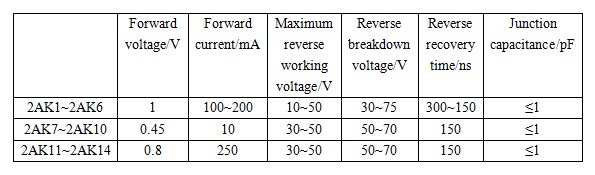
The main parameters of 2AK series switching diodes
2 High-Speed Switching Diode
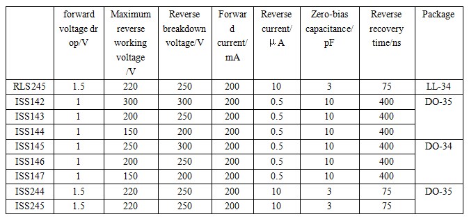
High-speed switching diodes have significantly shorter reverse recovery times compared to general switching diodes and can operate at faster on/off frequencies. Commonly used domestic high-speed switching diodes include the 2CK series, 1N series, 1S series, and 1SS series (leaded plastic package), as well as the RLS series (surface mount). These diodes are essential in high-frequency applications such as RF switching, pulse circuits, and fast rectification. Modern variants include Schottky barrier diodes and fast recovery diodes, which offer even better performance for specific applications.

High-speed diode model parameters
3 Ultra-High-Speed Switching Diode
Commonly used ultra-high-speed diodes include the 1SS series (leaded plastic package) and RLS series (surface package). These diodes feature reverse recovery times typically below 4 nanoseconds and are designed for applications requiring extremely fast switching, such as high-frequency switching power supplies, video signal processing, and advanced communication systems. PIN diodes are also frequently used in ultra-high-speed applications due to their excellent high-frequency characteristics.

Ultra-high-speed switching diode model parameters
4 Low Power Switching Diode
Low-power switching diodes feature lower power consumption, though their zero-bias capacitance and reverse recovery time values are typically higher than those of high-speed switching diodes. Commonly used low-power switching diodes include the RLS series (surface package) and 1SS series (leaded plastic package). These diodes are ideal for battery-powered devices, portable electronics, and applications where energy efficiency is paramount, such as IoT sensors and wearable technology.

Low power switching diode parameters
5 High Back Pressure Switching Diode
High back pressure (high reverse voltage) switching diodes have reverse breakdown voltages above 220V, though their zero-bias capacitance and reverse recovery time values are relatively large. Commonly used high back pressure switching diodes include the RLS series (surface package) and 1SS series (leaded plastic package). These diodes are essential in power supply circuits, AC-DC converters, and industrial equipment where high voltage handling capability is required.
Model parameters of high back pressure switching diode
6 Silicon Voltage Switching Diodes
Silicon voltage switching diodes are specialized semiconductor devices divided into unidirectional voltage switching diodes and bidirectional voltage switching diodes. They are primarily used in flip-flop circuits, overvoltage protection circuits, pulse generators, high-voltage output circuits, delay circuits, electronic switches, and various other applications.

Main parameters of two commonly used silicon voltage switching diodes
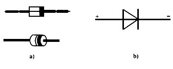
Unidirectional voltage switching diode outline drawing and circuit graphic symbols
Unidirectional voltage switching diodes, also called breakover diodes, consist of silicon semiconductor materials with a four-layer PNPN structure. In the forward direction, they exhibit negative resistance switching characteristics (meaning that when the applied voltage rises to the forward breakover voltage value, the switching diode changes from the off-state to the on-state, transitioning from high resistance to low resistance), while in the reverse direction they exhibit stable voltage characteristics. Bidirectional voltage diodes are composed of five-layer NPNPN silicon semiconductor material and exhibit the same negative resistance switching characteristics in both forward and reverse directions.

Outline drawing and circuit graphic symbol of bidirectional voltage switching diode
Ⅴ Typical Application Circuit Analysis of Switching Diodes
1. LC Resonant Circuit Control
The figure below shows a typical diode switching circuit. VD1 in the circuit is a switching diode, and L1 and capacitor C1 form an LC parallel resonant circuit.

(1) Switch S1 Off: When switch S1 is open, the DC voltage +V cannot reach the anode of VD1. At this time, VD1 is cut off, and the resistance between the anode and cathode is very high. Consequently, C2 is effectively disconnected from the circuit due to the open circuit at VD1. L1 and C1 form an LC parallel resonant circuit with a specific resonant frequency determined by these two components alone.
(2) Switch S1 On: When switch S1 is closed, the DC voltage +V is applied to the anode of VD1 through S1 and R1, turning on VD1. The resistance between the anode and cathode becomes very small, effectively connecting these terminals. In this state, C2 is connected to the circuit and placed in parallel with capacitor C1. Now L1, C1, and C2 form an LC parallel resonant circuit with a different resonant frequency.
In these two states, due to the different total capacitances in the LC parallel resonant circuit (C1 alone versus C1 and C2 in parallel), the resonance frequency of the circuit changes. Therefore, the primary function of VD1 and its associated circuitry is to control the resonance frequency of the LC parallel resonant circuit, enabling frequency-selective or tuning applications.
When analyzing circuits with switches, it is helpful to examine both the switch-on and switch-off cases to understand the complete circuit behavior. The AC signal in the LC parallel resonant circuit is coupled to the anode of VD1 through C2. However, because the signal amplitude in the resonant circuit is relatively small, the positive half-cycle signal amplitude applied to the anode of VD1 is insufficient to forward-bias and conduct VD1, ensuring that the DC control voltage remains the primary switching mechanism.
2. AC Signal Grounding Control Circuit
As shown in the figure below, VD1 in the circuit is a switching diode, and the control voltage is applied to the anode of VD1 through R1. The control voltage is a rectangular pulse voltage, with the waveform shown in the figure.

Operation: When the control voltage is 0V, VD1 cannot conduct and is effectively an open circuit. At this time, it does not affect the L1-C1 and L2-C2 circuits, and signals can pass through normally. When the control voltage is high (logic high level), the control voltage forward-biases and turns on the switching diode VD1. The AC signal at point A in the circuit is then grounded through the conducting VD1 and coupling capacitor C3, effectively creating an AC ground at point A. This makes the L2-C2 circuit inoperative, blocking signal transmission through this path.
From this analysis, it is clear that diode VD1 functions as an electronically controlled switch that determines whether the AC signal at point A is grounded or allowed to pass. This type of circuit is commonly used in signal routing, multiplexing applications, and automatic gain control systems.
Ⅵ How to Test Switching Diodes?
1. Testing Polarity
Set the multimeter to the R×100 or R×1k resistance range. Connect the two test leads to the two terminals of the diode. After the first measurement, reverse the two test leads and measure again. Among the two measurement results, one will show a larger resistance value (reverse resistance) and the other a smaller resistance value (forward resistance). In the measurement with the smaller resistance, the black test lead is connected to the anode of the diode, and the red test lead is connected to the cathode of the diode.
Note: Modern digital multimeters often have a dedicated diode test function (usually marked with a diode symbol). This function applies a small forward voltage and displays the forward voltage drop directly, typically around 0.3V for germanium diodes and 0.6-0.7V for silicon diodes. This method is more accurate and convenient than resistance measurement.
2. Testing Unidirectional Conduction Performance and Determining Condition
Generally, the forward resistance value of germanium material diodes is approximately 1kΩ, and the reverse resistance value is approximately 300kΩ or higher. The forward resistance value of silicon material diodes is approximately 5kΩ, and the reverse resistance value approaches infinity (∞) or is at least several megohms. The smaller the forward resistance, the better, and the larger the reverse resistance, the better. The greater the difference between the forward and reverse resistance values, the better the unidirectional conductivity of the diode.
If the measured forward and reverse resistance values of the diode are both close to zero or both show low resistance, this indicates that the diode has suffered a breakdown short circuit or is damaged. If the measured forward and reverse resistance values of the diode are both infinite (or extremely high), this indicates that the diode has an open circuit and is damaged.
3. Advanced Testing Methods (2025)
For more comprehensive testing of switching diodes, especially for high-speed and ultra-high-speed types, the following parameters should be evaluated using specialized equipment:
• Reverse Recovery Time (trr): Use an oscilloscope with a fast pulse generator to measure the time required for the diode to switch from forward conduction to complete cutoff.
• Junction Capacitance: Use an LCR meter at the specified frequency (typically 1 MHz) to measure the junction capacitance under zero-bias conditions.
• Forward Voltage Drop: Measure at the rated forward current to ensure it falls within the specified range.
• Reverse Leakage Current: Apply the maximum rated reverse voltage and measure the leakage current, which should be minimal (typically in the microampere or nanoampere range).
Ⅶ Modern Applications and Future Trends
As of 2025, switching diodes have expanded into numerous emerging application areas beyond their traditional uses:
1. Wireless Communication Systems: Band switching diodes play crucial roles in modern 5G networks and wireless communication systems, enabling better signal routing and frequency switching. They are essential components in RF front-end modules, antenna tuning circuits, and software-defined radio systems.
2. Automotive Electronics: The automotive industry's shift toward electrification has driven demand for high-reliability switching diodes in electric vehicle (EV) power management systems, battery management circuits, and advanced driver assistance systems (ADAS). The power diode market growth to $2.61 billion in 2025 is largely attributed to automotive applications.
3. Renewable Energy: Switching diodes are critical components in solar inverters, wind turbine power converters, and energy storage systems. High-efficiency, fast-switching diodes help minimize power losses in these applications.
4. IoT and Wearable Devices: Low-power switching diodes are increasingly important in Internet of Things (IoT) sensors, wearable health monitors, and battery-powered devices where energy efficiency is paramount.
5. Emerging Technologies: Research is exploring the use of switching diodes in quantum computing circuits, biomedical implantable devices, and advanced photonic systems. Wide bandgap semiconductor materials such as silicon carbide (SiC) and gallium nitride (GaN) are being used to create switching diodes with superior high-temperature performance and faster switching speeds.
Future Trends:
• Development of ultra-low capacitance diodes for higher frequency applications (millimeter-wave and terahertz frequencies)
• Integration of switching diodes with other semiconductor devices in system-in-package (SiP) solutions
• Enhanced thermal management capabilities for high-power applications
• Improved reliability and longer operational lifetimes for mission-critical applications
• Miniaturization through advanced packaging technologies such as wafer-level chip-scale packages (WLCSP)
Article Recommendations:
Schottky Diodes: Principle, Functions, and Applications
Best 1N4007 Diode Alternatives to Use in 2025
Article Update Information:
This article was originally published in 2020 and has been comprehensively updated in October 2025 to reflect current technology standards, market trends, and emerging applications. Updates include: modern testing methods using digital multimeters, expanded application areas including 5G communications and electric vehicles, current market data showing growth to $2.61 billion in 2025, information on wide bandgap semiconductor materials (SiC and GaN), emerging applications in IoT and wearable devices, and future trends in switching diode technology. All technical specifications and parameters have been verified for accuracy as of 2025.
 UTMEL
UTMEL
We are the professional distributor of electronic components, providing a large variety of products to save you a lot of time, effort, and cost with our efficient self-customized service. careful order preparation fast delivery service
1.How does a diode act as a switch?
Whenever a specified voltage is exceeded, the diode resistance gets increased, making the diode reverse biased and it acts as an open switch. Whenever the voltage applied is below the reference voltage, the diode resistance gets decreased, making the diode forward biased, and it acts as a closed switch.
2.Which diode is used for fast switching?
Depending on the application, switching diode can also operate as a simple rectifier diode,transient-voltage-suppressor or detection diode). It is characterized by a very fast operation rate (measured in nanoseconds, whereas for higher voltages – microseconds).
3.Can you put a diode in backwards?
Without a diode semiconductor, this kickback voltage would damage the control equipment. When properly installed, the diode keeps kickback voltage localized at the lock. Installing the diode backward for a strike can cause the Cloud Node or the door controller to reboot.
4.Where are switching diodes used?
A switching diode is suitable for switching a small signal of up to 100 mA, acting as a rectifier. In contrast, a rectifier diode is used for AC line rectification (from alternating current to direct current). Switching diodes are designed to handle a voltage of less than tens of volts.
5.Can you put two diodes in parallel?
If the load current is greater than the current rating of a single diode, then two or more diodes can be connected in parallel (see Figure 1) to achieve a higher forward current rating. Diodes connection in parallel do not share the current equally due to different forward bias characteristics.
 All You Need to Know About Rectifier CircuitUTMEL24 April 202517208
All You Need to Know About Rectifier Circuit
Read More 15 Key Elements of Diode SelectionUTMEL26 November 202118673
Hello everyone, I am Rose. Welcome back to the new post today. Diodes are one of the most common components in our circuit boards. So, what factors should be considered when selecting models?
Read More What is a PIN Diode?UTMEL04 February 20219885
While diodes with a simple PN junction are by far the most common type of diode in operation, in a variety of applications, other forms of diode may be used. The PIN diode is one type that is used for a number of circuits. In a variety of places, this diode type is used. For RF switching, the PIN diode is very fine, and the PIN structure in photodiodes is very useful as well.
Read More Microwave Diode: Introduction and TypesUTMEL07 January 202125171
Microwave diodes are diodes that work in the microwave frequency band. It is a solid-state microwave device. Microwave band usually refers to the frequency from 300 MHz to 3000 GHz. After the discovery of the point contact diode effect at the end of the 19th century, microwave diodes such as PIN diodes, varactor diodes, and Schottky diode tubes appeared one after another. Microwave diodes have the advantages of small size and high reliability, and are used in microwave oscillation, amplification, frequency conversion, switching, phase shifting and modulation.
Read More What Determines the Maximum Operating Frequency of a Diode?UTMEL29 June 202212620
Hello, wish you a wonderful day. In this essay, we first pose the following query: what determines the diode's maximum operating frequency? In regards to the solution, the first thing we need to understand is that the junction capacitance and the reverse recovery time of the diode are two distinct concepts. The charging and discharging times of the junction capacitance cannot match the reverse recovery time. You say that, why? Let's start by taking a look at these facts.
Read More
Subscribe to Utmel !
![BLM18BB220SN1D]() BLM18BB220SN1D
BLM18BB220SN1DMurata Electronics
![BLM15BD221SN1D]() BLM15BD221SN1D
BLM15BD221SN1DMurata Electronics
![MPZ1608S601ATD25]() MPZ1608S601ATD25
MPZ1608S601ATD25TDK Corporation
![BLM15BB470SN1D]() BLM15BB470SN1D
BLM15BB470SN1DMurata Electronics
![NFM21CC471R1H3D]() NFM21CC471R1H3D
NFM21CC471R1H3DMurata Electronics
![BLM18HG471SN1D]() BLM18HG471SN1D
BLM18HG471SN1DMurata Electronics
![ST1284-01A8RL]() ST1284-01A8RL
ST1284-01A8RLSTMicroelectronics
![MMZ2012R102AT000]() MMZ2012R102AT000
MMZ2012R102AT000TDK Corporation
![MMZ2012Y102BTD25]() MMZ2012Y102BTD25
MMZ2012Y102BTD25TDK Corporation
![BKP1005HS221-T]() BKP1005HS221-T
BKP1005HS221-TTaiyo Yuden


