Product
 Brand
Brand Articles
 Tools
Tools
All You Need to Know About Rectifier Circuit

Introduction to Diode Rectifier Circuits
Catalog
2. Rectifier circuit classification
1. What is a rectifier circuit?
The function of the rectifier circuit is to convert the low-voltage AC power output by the AC step-down circuit into a unidirectional pulsating DC power. This is the rectification process of the AC power. The rectifier circuit is mainly composed of rectifier diodes. The voltage after passing through the rectifier circuit is no longer AC voltage, but a mixed voltage containing DC voltage and AC voltage. It is customarily called unidirectional pulsating DC voltage.
Most rectifier circuits are composed of transformers, rectifier main circuits, and filters. It is widely used in the fields of DC motor speed regulation, generator excitation regulation, electrolysis, electroplating, and so on. After the 1970s, the main circuit is mostly composed of silicon rectifier diodes and thyristors. The filter is connected between the main circuit and the load to filter out AC components in the pulsating DC voltage. The setting of the transformer depends on the specific situation. The function of the transformer is to achieve the matching between the AC input voltage and the DC output voltage and the electrical isolation between the AC power grid and the rectifier circuit.
Basic principles of rectification
Rectification is the process of converting alternating current (AC) into unidirectional pulsating direct current (DC) by utilizing the unidirectional conductivity of the diode. When the AC voltage is positive half-cycle, the diode conducts positively and current passes through; when the AC voltage is negative half-cycle, the diode cuts off negatively and current is blocked. Different types of rectification can be realized through different diode combinations.
The rectified voltage still contains a large AC component (called ripple) and usually needs to be further processed by a filter circuit to obtain a smooth DC voltage.
2. Rectifier circuit classification
Usually, the DC stabilized power supply uses a power transformer to change the voltage input to the subsequent circuit. The power transformer is composed of a primary winding, a secondary winding, and an iron core. The primary winding is used to input the AC voltage of the power supply, and the secondary winding outputs the required AC voltage. Transformers work through the principle of electromagnetic induction, converting the alternating current from the primary coil into an alternating magnetic field in the iron core, and then the secondary coil converts the magnetic field into alternating current at the desired voltage. When the secondary is connected to the load, the circuit is closed and an alternating current flows through the secondary circuit.
The alternating current is still alternating current after being transformed by the transformer, and it needs to be converted to direct current before it can be supplied to the subsequent circuit. This conversion circuit is the rectifier circuit. The rectifier circuit uses the single conductivity characteristic of the diode in the DC stabilized power supply to rectify the alternating current that changes in the direction into direct current.
2.1. Half-wave rectifier circuit
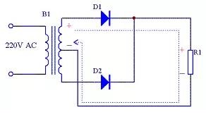
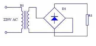
The half-wave rectifier circuit is shown in Figure 1. Among them, B1 is the power transformer, D1 is the rectifier diode, and R1 is the load.
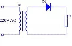
B1 secondary is a sine wave voltage whose direction and magnitude change with time, the waveform is shown in Figure 2(a). The period from 0 to π is the positive half cycle of this voltage. At this time, the upper end of the B1 secondary is positive and the lower end is negative. The diode D1 is in forwarding conduction, and the power supply voltage is applied to the load R1, and the current flows through the load R1. The period from π to 2π is the negative half cycle of the voltage. The upper end of the secondary B1 is negative and the lower end is positive, the diode D1 is reversely cut off. No voltage is applied to the load R1, and no current flows in the load R1.
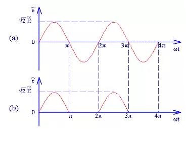
Repeat the above process in the subsequent cycles of 2π~3π, 3π~4π, etc., so that the waveform of the negative half cycle of the power supply is "cut" and a single direction voltage is obtained. The waveform is shown in Figure 2(b). Since the size of the voltage waveform obtained in this way changes with time, we call it pulsating direct current.
Suppose the secondary voltage of B1 is E, and the voltage across the load R1 in an ideal state can be calculated by the following formula:
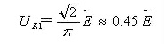
Figure 3. Half-wave rectification calculation formula
The reverse peak voltage of the rectifier diode D1 is:

Figure 4. Calculation formula of the reverse peak voltage of half-wave rectifier diode
Since the half-wave rectifier circuit only uses the positive half cycle of the power supply, the utilization efficiency of the power supply is very low, so the half-wave rectifier circuit is only used in a few cases such as high voltage and small current, and is rarely used in general power circuits.
Although the half-wave rectifier circuit has a simple structure, it utilizes only the positive half-cycle of the alternating current, resulting in low power utilization and a large ripple coefficient of the output voltage. In order to improve power utilization and reduce ripple, full-wave rectifier circuits have emerged. Full-wave rectifier circuits are able to utilize both the positive and negative half cycles of the alternating current so that the frequency of the output voltage is twice the frequency of the input, thus making filtering easier.
2.2. Full-wave rectifier circuit
Because the efficiency of the half-wave rectifier circuit is low, people naturally think of using the negative half cycle of the power supply, so that there is a full-wave rectifier circuit. The full-wave rectifier circuit diagram is shown in Figure 5.
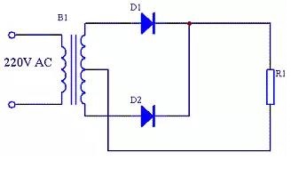
Compared with the half-wave rectifier circuit, the full-wave rectifier circuit uses a rectifier diode D2, and the secondary of the transformer B1 also adds a center tap. This circuit essentially combines two half-wave rectifier circuits together. During the period from 0 to π, the upper end of B1 secondary is positive and the lower end is negative. D1 is forward conducting, and the power supply voltage is applied to R1. The upper end of the voltage across R1 is positive and the lower end is negative. The waveform is shown in Figure 6(b), the current flow is shown in Figure 7.
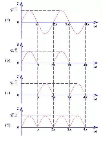
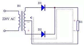
During the period of π~2π, the upper end of B1 secondary is negative and the lower end is positive. D2 is forward conducting, and the power supply voltage is applied to R1. The voltage at both ends of R1 is still positive and the lower end is negative. The waveform is shown in Figure 6 (c), the current flow is shown in Figure 8. Repeat the above process in the subsequent cycles of 2π~3π, 3π~4π, etc., so that the positive and negative voltages of the two half cycles of the power supply are rectified by D1 and D2 and then applied to both ends of R1. The voltage obtained on R1 is always positive and negative. The waveform is shown in Figure 6 (d).
Suppose the secondary voltage of B1 is E, and the voltage across the load R1 in an ideal state can be calculated by the following formula:
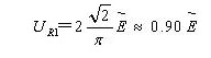
Figure 9. The full-wave rectification calculation formula
The reverse peak voltage of the rectifier diodes D1 and D2 is:
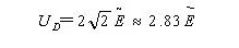
Figure 10. Calculation formula of the reverse peak voltage of full-wave rectifier diode
The current flowing through each rectifier diode of the full-wave rectifier circuit is only half of the load current, which is twice as small as the half-wave rectifier.
2.3. Bridge rectifier circuit
Since the full-wave rectifier circuit requires a special transformer, it is more troublesome to manufacture, so a bridge rectifier circuit appears. This rectifier circuit uses an ordinary transformer but uses two more rectifier diodes than full-wave rectification. Since the four rectifier diodes are connected in the form of a bridge, this rectifier circuit is called a bridge rectifier circuit.
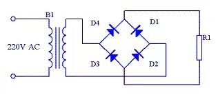
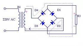
From Figure 12, it can be seen that during the positive half cycle of the power supply, the upper end of the B1 secondary is positive and the lower end is negative. The rectifier diodes D4 and D2 conduct. The current flows from the upper end of the transformer B1 secondary through D4, R1, D2, and returns to the lower end of the transformer B1 secondary.
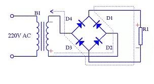
From Figure 13, it can be seen that during the negative half cycle of the power supply, the lower end of the B1 secondary is positive and the upper end is negative. The rectifier diodes D1 and D3 conduct, and the current returns from the lower end of the transformer B1 secondary to the upper secondary of transformer B1 through D1, R1, and D3. The voltage across R1 is always positive and negative, and its waveform is consistent with that of full-wave rectification.
Suppose the secondary voltage of B1 is E, and the voltage across the load R1 in an ideal state can be calculated by the following formula:
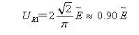
Figure 14. Bridge rectifier calculation formula
The reverse peak voltage of the rectifier diodes D1 and D2 is:

Figure 15. The formula for calculating the reverse peak voltage of bridge rectifier diodes
The current flowing through each rectifier diode of the bridge rectifier circuit is half of the load current, which is the same as full-wave rectification.
Under normal circumstances, the bridge rectifier circuit is simplified to the form shown in Figure 16.
Bridge Rectification vs. Full Wave Rectification
Bridge rectifier circuits have several advantages over full wave rectifier circuits:
No need for a center-tapped transformer, using an ordinary transformer can be, reducing cost and complexity
The output voltage is the same as the full-wave rectifier, which is about 0.9 times the input peak voltage
Each diode withstand reverse peak voltage only input peak voltage, while the full-wave rectifier for the input peak voltage of 2 times
The disadvantages are that four diodes are required instead of two, which increases the component cost, and each diode has a voltage drop, which may result in a large energy loss in low-voltage applications.
2.4. Voltage doubler rectifier circuit
The output voltage of the three rectifier circuits introduced above is less than the effective value of the input AC voltage. If the output voltage is required to be greater than the effective value of the input AC voltage, a voltage doubler circuit can be used, as shown in Figure 17.
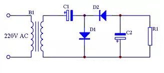
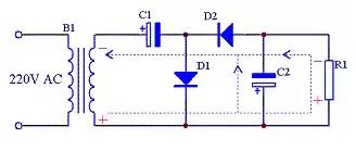
It can be seen from Figure 18 that in the positive half cycle of the power supply, the upper end of the transformer B1 secondary is positive and the lower end is negative, D1 is on, D2 is off, and C1 is charged through D1. After charging, the voltage across C1 is close to the peak value of the secondary voltage of B1. The direction is positive on the left and negative on the right.
It can be seen from Figure 19 that in the negative half cycle of the power supply, the upper end of the transformer B1 secondary is negative and the lower end is positive, D1 is off, D2 is on, and C2 is charged through D1. After charging, the voltage across C2 is close to the voltage across C1. The sum of the peak values of the secondary voltage of B1, the direction is the lower end is positive and the upper end is negative. Since load R1 is connected in parallel with C1, when R1 is large enough, the voltage across R1 is close to twice the B1 secondary voltage.
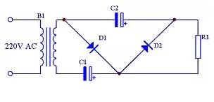
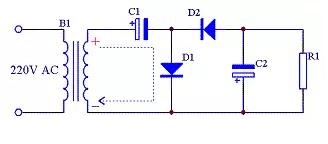
There is another way of drawing the double voltage rectifier circuit. As shown in Figure 20. The principle is exactly the same as that in Figure 17, but the form of expression is different.
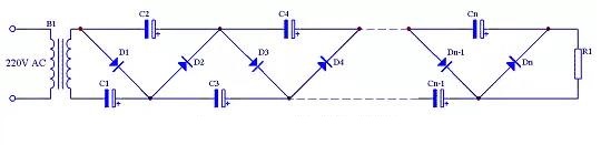
The double voltage circuit can also be easily expanded into an n double voltage circuit. The specific circuit is shown in Figure 21.
2.5. Filtering techniques for rectifier circuits
The rectified pulsating DC contains a large AC component, which requires a filter circuit to reduce the ripple and obtain a smooth DC. Commonly used filtering methods include:
Capacitive Filtering
The most commonly used filtering method utilizes the charging and discharging characteristics of capacitors to smooth the voltage waveform. Capacitor filter circuit is simple and low cost, but the ripple suppression ability is limited.
LC Filtering
Combination of inductor and capacitor filtering, the filtering effect is better than capacitor filtering alone, but the cost is higher and the volume is larger.
π-Type Filtering
Consisting of two capacitors and one inductor, it has better filtering effect and is often used in demanding power supply circuits.
The choice of filter circuit depends on factors such as load requirements, cost budget and space constraints.
2.6. Limitations and solutions of rectifier circuits
Ripple problem
The rectified voltage contains obvious ripple components, which will lead to unstable load operation. The solution is to add a filtering circuit. Commonly used filtering circuits include capacitor filtering, inductor filtering and LC filtering.
Voltage Drop Problems
The forward voltage drop of a diode (about 0.7V) can cause significant energy loss in low voltage applications. The solution is to use Schottky diodes (voltage drop of about 0.3V) or synchronous rectification techniques.
Efficiency Issues
Conventional rectifier circuits typically have efficiencies of around 80%. Modern power supply designs can increase efficiency to over 95% by using techniques such as synchronous rectification and resonant rectification.
3. Practical applications of rectifier circuits
Cell phone chargers
Modern cell phone chargers usually use bridge rectifier circuits to convert 220V AC to DC and then step down to about 5V by switching power supply technology.
Power Adapter
Power adapters for laptops, monitors, and other devices contain rectifier circuits that convert AC power to the DC power needed by the device.
Power tool chargers
Chargers for rechargeable power tools such as drills, chainsaws, etc. use rectifier circuits to convert AC power to DC power to charge the batteries.
Solar Power System
The inverter in a solar power system contains rectifier circuits to convert the DC power generated by solar cells into AC power for household use.
 UTMEL
UTMEL
We are the professional distributor of electronic components, providing a large variety of products to save you a lot of time, effort, and cost with our efficient self-customized service. careful order preparation fast delivery service
1. What is rectifier circuit and why it is needed?
Rectifiers are essential circuits for power supplies that convert an AC input voltage into a DC voltage supply that can be used to power electronic circuits.
2. Why is the rectification process important?
Rectification is the process of converting bidirectional current flow to unidirectional current flow. The process is of vital importance in many areas of circuit design, including radio communication and AC to DC power conversion.
 All You Need to Know About Rectifier CircuitUTMEL24 April 202517610
All You Need to Know About Rectifier Circuit
Read More 15 Key Elements of Diode SelectionUTMEL26 November 202118902
Hello everyone, I am Rose. Welcome back to the new post today. Diodes are one of the most common components in our circuit boards. So, what factors should be considered when selecting models?
Read More What is a PIN Diode?UTMEL04 February 202110229
While diodes with a simple PN junction are by far the most common type of diode in operation, in a variety of applications, other forms of diode may be used. The PIN diode is one type that is used for a number of circuits. In a variety of places, this diode type is used. For RF switching, the PIN diode is very fine, and the PIN structure in photodiodes is very useful as well.
Read More Microwave Diode: Introduction and TypesUTMEL07 January 202126026
Microwave diodes are diodes that work in the microwave frequency band. It is a solid-state microwave device. Microwave band usually refers to the frequency from 300 MHz to 3000 GHz. After the discovery of the point contact diode effect at the end of the 19th century, microwave diodes such as PIN diodes, varactor diodes, and Schottky diode tubes appeared one after another. Microwave diodes have the advantages of small size and high reliability, and are used in microwave oscillation, amplification, frequency conversion, switching, phase shifting and modulation.
Read More What Determines the Maximum Operating Frequency of a Diode?UTMEL29 June 202212925
Hello, wish you a wonderful day. In this essay, we first pose the following query: what determines the diode's maximum operating frequency? In regards to the solution, the first thing we need to understand is that the junction capacitance and the reverse recovery time of the diode are two distinct concepts. The charging and discharging times of the junction capacitance cannot match the reverse recovery time. You say that, why? Let's start by taking a look at these facts.
Read More
Subscribe to Utmel !
![BLM18KG601SH1D]() BLM18KG601SH1D
BLM18KG601SH1DMurata Electronics
![BLM15BC121SN1D]() BLM15BC121SN1D
BLM15BC121SN1DMurata Electronics
![MMZ2012S800AT000]() MMZ2012S800AT000
MMZ2012S800AT000TDK Corporation
![MMZ1608D121CTAH0]() MMZ1608D121CTAH0
MMZ1608D121CTAH0TDK Corporation
![NFM3DCC102R1H3L]() NFM3DCC102R1H3L
NFM3DCC102R1H3LMurata Electronics
![NFM31KC223R1H3L]() NFM31KC223R1H3L
NFM31KC223R1H3LMurata Electronics
![MMZ1608B102CTD25]() MMZ1608B102CTD25
MMZ1608B102CTD25TDK Corporation
![MMZ1608Y600BTA00]() MMZ1608Y600BTA00
MMZ1608Y600BTA00TDK Corporation
![HFCN-1760]() HFCN-1760
HFCN-1760Mini-Circuits
![BLM03BD750SN1D]() BLM03BD750SN1D
BLM03BD750SN1DMurata Electronics