AC/DC, DC/DC Converter Fundamental Guide

how to convert AC to DC
| Topics covered in this article: |
| Ⅰ. AC/DC converter |
| Ⅱ. DC/DC converter |
| Ⅲ. Types of Power ICs |
| Ⅳ. What is LDO? |
First, let's go over the concepts of AC (alternating current) and DC (direct current).
What is AC?

Acronym for Alternating Current.
AC is an electrical current whose magnitude and polarity (direction) change repeatedly throughout time.
The frequency, which is measured in Hz, is the number of times the current polarity changes in one second.
What is DC?
Acronym for Direct Current.
The polarity (direction) of a DC current does not vary over time.
①A DC current is defined as one whose flow polarity (direction) and magnitude do not fluctuate over time.

② Although the flow polarity does not change with time, the current whose amplitude does is also DC, and is known as Ripple current.

Ⅰ. AC/DC Converter
What is an AC/DC Converter?
An AC/DC converter is an element that converts AC (alternating voltage) into DC (direct current voltage).
Why do you need an AC/DC Converter?
Because family dwellings and buildings receive 100V or 200V AC voltage, this is the case.
The majority of your electrical equipment, on the other hand, works on a DC voltage of 5V or 3.3V.
That is, the appliance will not function unless the AC voltage is converted to DC voltage.

There are also goods that can be operated by AC voltage, such as motors and light bulbs, but because the motors are connected to the microcontroller's control circuit and the light bulbs also become energy-saving LEDs, ACDC conversion is required.
Why is AC voltage transmitted?
"Since the appliance uses DC, why not send DC in the first place?" some may reason.
Hydroelectric power plants, thermal power plants, nuclear power plants, and other sources of electricity are all well-known. These power plants are located in mountainous or coastal areas, and AC voltage is more advantageous between these areas and urban centers.
In short, transmission loss (energy loss) can be reduced by transferring AC power with high voltage and low current.
However, because high voltage cannot be utilized directly in a residence, it must be transformed (stepped down) in steps through multiple substations before being converted to 100V or 200V and then entered. Because AC is used in these conversions, the AC voltage is transferred.
Full-wave rectification and half-wave rectification (AC/DC conversion)
When converting AC (alternating voltage) to DC, there are two methods: full-wave rectification and half-wave rectification (direct voltage). The forward current flow characteristic of the diode is used for rectification in both circumstances.

Full-wave rectification is the process of converting the negative voltage component of an input voltage into a positive voltage and then rectifying it into a DC voltage using a diode bridge circuit construction (pulse voltage). A diode is used in half-wave rectification to eliminate the negative voltage component in the input and rectify it into a DC voltage (pulse voltage).
The waveform is then flattened by the capacitor's charging and discharging operation before being transformed to a pure DC voltage.
As a result, full-wave rectification, which does not use input negative voltage components, is a more efficient rectification approach than half-wave rectification.
In addition, the smoothed ripple voltage varies with capacitor capacity and load (LOAD).
Under the same capacitor capacity and load conditions, the ripple voltage of full-wave rectification is lower than that of half-wave rectification. The higher the stability and the better the performance, the lower the ripple voltage.
AC/DC conversion method
AC/DC conversion has a transformer method and a switching method.
Transformer method
This is the transformer-type circuit structure of an ordinary AC/DC converter.
[Example of the circuit configuration of the transformer method]

The voltage waveform changes in the transformer mode, as seen in the diagram below.
The transformer approach necessitates first scaling down the AC voltage to the suitable AC voltage via a transformer (eg, from AC100V to AC10V, etc.). The transformer's winding ratio determines the step-down value in this AC/AC conversion.
The full-wave rectified AC voltage stepped down by the transformer is then turned into a pulse voltage using a diode bridge rectifier.
Finally, the capacitor smooths down the voltage and outputs a DC voltage with little ripple, which is the most common AC/DC conversion method.
[Transformation of the waveform of the transformer method]

Switch mode
This is the switch-mode circuit structure of an ordinary AC/DC converter.
[Example of circuit configuration of switching method]

In switching mode, the voltage waveform changes as shown in the diagram below.
The transformer approach involves using a transformer to conduct AC/AC step-down, while the switch method involves directly rectifying the AC voltage with a diode bridge rectifier. Because most residential power is AC100V or AC200V, the diode bridge rectifier must have requirements that can handle high voltages.
After that, use a capacitor to smooth down the DC voltage (pulse voltage). High-voltage-resistant capacitors are also required for capacitors.
The DC voltage is then chopped (cut) by the switching element's ON/OFF, and the voltage is stepped down and transferred to the secondary side by a high-frequency transformer. The chopping waveform transforms into a square wave at this point.
In comparison to household frequencies (50/60Hz), switching elements employ higher frequencies (e.g. 100kHz). Miniaturization and weight reduction of the transformer are possible due to the high-frequency operation.
[Waveform transition of switching method]

On the secondary side, a rectifier diode half-wave rectifies the square wave, which is then smoothed by a capacitor and output as a DC voltage.
The switching approach employs a control circuit to regulate the switching element and produce a predictable DC output (for example, DC12V).
The switching technique, as opposed to the transformer approach, is made up of switching elements and control circuits, and the circuit topology is more complex. However, because a small transformer may be utilized with high-frequency control, it contributes to the equipment's miniaturization, which is a significant benefit.
Feedback control
What is feedback control?
The switching AC/DC converter validates the actual output DC voltage value and regulates the switching element based on this information, ensuring that the intended DC output is realized in a reliable manner. The feedback control method confirms the output voltage value to control the switching element (FB control).

Example of Switching Circuit Structure
Schematic diagram of feedback control
A switching AC/DC converter converts AC electricity to DC voltage by rectifying it with a diode bridge and smoothing it out with a capacitor. The DC voltage is then chopped (ON/OFF) by a switching element, then stepped down by a high-frequency transformer and sent to the secondary side, before being smoothed out by a capacitor to provide a specified DC value (VDC).
The FB control circuit determines whether the actual output voltage value is equal to or greater than the target voltage value.

Schematic Diagram of Output Voltage After Smoothing
The switching element is adjusted to make the ON time longer when the actual output voltage value is lower than the goal voltage value. As a result, the output voltage will increase. When the voltage is higher than the target voltage value, however, the control ON time is reduced.
As a result, the feedback control circuit constantly validates the actual output voltage value and adjusts the ON/OFF duration of the switching element to ensure the target output voltage value's stability.
Light load mode
What is light load mode?
Light load mode is a strategy for increasing efficiency while using less output current. It's also known as burst mode in DC/DC converters and other electronic devices.
To provide a stable output voltage value, switching AC/DC and DC/DC converters use ON/OFF conversion to accomplish voltage chopping and capacitor smoothing.
During ON/OFF, however, this switching generates a brief leakage current (through current). That is, the greater the loss caused by leakage current and the poorer the efficiency, the more ON/OFF times per unit time.
Even though the ON/OFF time ratio changes when the period is constant (PWM control), the number of occurrences per unit time remains constant. As a result, self-dissipated power remains constant, and switching leakage current losses at light loads degrade efficiency. As a result, when less current is utilized, frequency modulation (PFM control) is employed to extend and slow down the cycle, minimizing the number of ON/OFF transitions per unit time and lowering losses. This method is known as light load mode.

PWM Method and PFM Method
The usage of PWM and PFM can boost efficiency even more depending on the situation. When the load is large (current is used), the cycle-constant PWM control is employed, and when the load is light, the cycle-variable PFM control is used (current is not used).
■PWM (Pulse Width Modulation): The frequency is constant, and the output part's control mode is triggered by the input voltage.
■PFM (Pulse Frequency Modulation): A way of summoning the output component by varying the frequency while keeping the ON time constant (changing the OFF time). On the other hand, there are ways to fix the OFF time and change the ON time. PWM and PFM are two different types of power management systems.
The PFM method has high efficiency and changes the frequency according to the amount of output current, although noise occurs intermittently during switching. It's difficult to get rid of noise whose frequency can't be established. It is easier to solve the noise by using a PWM approach with a constant frequency.
Low-noise PWM and high-efficiency PFM can thus complement one another. PWM is utilized for high-frequency driving with high loads (which results in higher noise), while PFM is used for low loads and lower current usage. Boost productivity.
Ⅱ. DC/DC converter
What is a DC/DC Converter?
A DC/DC converter is a device that converts DC (direct current) to DC (direct current), and more precisely, a device that converts voltage using DC (direct current). Because electronic components, such as ICs, operate at different voltage ranges, they must be converted to the appropriate voltages.
A "buck converter" produces a voltage lower than the initial voltage, while a "boost converter" creates a voltage greater than the beginning voltage.
Name description
A device that converts direct current to direct current is known as a DC/DC converter.
Following the conversion process, it is commonly referred to as a linear regulator, switching regulator, or other terms.

Step-down power supply units Buck converters, Buck converters, Step-down converters
Voltage boosting power supply Boost converter, Boost converter, Step-up converter
Buck-Boost Power Supply Buck-Boost Converter, Buck-Boost Converter
Power supply units that generate negative voltages Negative voltage converters, inverting converters, inverting converters
Why do you need a DC/DC Converter?
An "AC/DC converter," which converts AC (alternating current) 100V to DC, is required for electrical items that are plugged into an outlet for operation (direct current).
Because most semiconductor components can only operate at DC, this is the case.
The working voltage range of the ICs installed on the circuit board of the entire machine is diverse, as are the voltage accuracy requirements.
Powering a device with an inconsistent voltage might result in faults or deterioration of its attributes.
As a result, a "DC/DC converter" is employed to convert to and stabilize the desired voltage.

A voltage regulator is a device that uses a DC/DC converter to accomplish voltage stabilization.
Ⅲ. Types of Power ICs
Linear regulators and switching regulators are the two basic types of power ICs.
Linear regulators can only step-down output voltages that are lower than the input voltage because of their output forms.
Switching regulators have four output types, each with its own degree of freedom:
・Step-down output voltage lower than input voltage
・Boost output voltage higher than input voltage
・The buck-boost output constant voltage, regardless of the input voltage
・Reverse output from positive voltage to negative voltage
Moreover, the rectification methods of switching regulators include synchronous rectification and asynchronous rectification (diode rectification).

Types of Power ICs
Linear and Switching Regulator
A voltage regulator is a device that uses a DC/DC converter to accomplish voltage stabilization.
Voltage regulators are classified into two sorts based on the conversion method: linear regulators and switching regulators.
Linear Regulator
It's called a "linear regulator" because the relationship between input and output is linear throughout operation.
Because a control element is connected in series between the input and output, it is also referred to as a "series regulator."

Because the control element steps down the voltage, the greater the voltage differential between the input and output (the degree of step-down), the higher the loss and the lower the efficiency.
As a result, it is appropriate for low-power power supplies.


Advantages: Simple circuit, Fewer external parts, low noise
Disadvantages: Low efficiency, Great fever, Buck converter only
Switching Regulator
The switching element (MOSFET) is activated, allowing power to flow from the input to the output until the output voltage reaches the desired level.
The switching element is shut off when the output voltage reaches the required value, and the input power is no longer utilized.
The output voltage is adjusted to a specified value by repeating this procedure at a rapid speed.
Advantages: efficient, low fever, Boost/buck/negative voltage conversion possible
Disadvantages: Many external parts, Design difficulties, Loud noise
How Linear Regulators Work
General pin configuration
A linear regulator has three pins: VIN (input), VO (output), and GND (ground) (ground).
A FB (feedback pin) is added to the linear regulator with variable output for feedback on the output voltage.
In a nutshell, a voltage stabilizer with a built-in voltage-variable external resistor is known as a voltage-fixed type.
The internal circuit of the linear regulator is depicted in the diagram below.

Internal Circuit
Its operation is similar to that of an inverting amplifier circuit. Because the error amplifier's non-inverting pin (FB) voltage is the same as the reference voltage (VREF), the output voltage value (VO) is determined by the ratio of the two resistors' resistance values (R1 and R2). Decide.
VREF=[(R1+R2) / R2] Vo=[(R1+R2) / R2]
The output transistor in the diagram below is a MOSFET, but bipolar transistors are also used in some products.

Classification of Linear Regulator
Sort by function
When it comes to function, there are two sorts of linear regulators: positive voltage and negative voltage.
There are also goods that do not require a positive power source but do require a negative power supply, depending on the circuit utilized.
If the power supply is just on the positive side, it will not be able to handle voltages below ground, and the voltage of the transistor's output pin will not be able to be distributed to a negative level. Connect the control transistor to the negative output line, resulting in a negative voltage.

Classified by Function
Second, it can be separated into two types: constant voltage and variable voltage. The fixed type contains three pins: input, output, and GND, as well as an integrated resistor for setting the output voltage.
When the variable is of the GND reference type, adding a feedback pin increases the number of pins to four. There is a floating operation type without a GND pin in the variable type, however, it has three pins in this case.

The voltage-fixed and voltage-variable kinds are further separated into two categories: standard and LDO.
Low Dropout (LDO) is an abbreviation for a linear regulator that lowers the potential difference between input and output. The standard type has a minimum potential difference between the input and output of roughly 2V, whereas the LDO can be controlled at less than 1V.
Ⅳ. What is LDO?
Low Dropout (LDO) is an abbreviation for a linear regulator that can work even when the potential difference between input and output is small.
It's also known as a low-saturation linear regulator or a low-loss linear regulator.
The potential difference between the LDO's input and output has no numerical definition. In general, it refers to a voltage stabilizer whose minimum potential difference can be controlled below 1V while it is working well.
Because the normal type cannot generate a 5V to 3.3V power supply, an LDO with a low potential difference between the input and output is required for an IC that requires a 3.3V power supply.
This allows the LDO to use a lower input voltage while still producing the same output voltage as a traditional regulator.
Energy loss and heat dissipation can both be decreased by operating at a low potential difference.
pressure drop
A transistor is introduced from VIN to VO inside the linear regulator, and the voltage drop is the minimal potential difference between the input and output required to make the transistor work reliably.
The transistor struggles to maintain stable operation when the voltage difference between the input and output is less than the voltage drop, and the output voltage drops.

In this approach, the required minimum input voltage value is set in order for the linear regulator with LDO to work, and (VO + voltage drop) is the regulator's minimum operating voltage value at this time.
The output voltage cannot work reliably if the input voltage value (VIN) is less than the minimum working voltage.
1. What does 12v power supply DC and AC mean?
AC is alternating current, and the direction of current changes periodically with time is alternating current. Its most basic form is sinusoidal current. DC is direct current, also known as constant current, which is a kind of direct current, with the same magnitude and direction.
2. What is the function of a DC/DC converter?
The function of the DC/DC converter is to effectively output a fixed voltage after converting the input voltage.
Basic principle: The output voltage is compared with the reference voltage through a voltage divider resistor to form a feedback. When the output voltage decreases and falls below the reference voltage, the comparator output flips and triggers the oscillator circuit to work. The oscillator circuit outputs a pulse with a fixed time for controlling the conduction of the MOS tube. Otherwise, the MOS tube will be cut off. The turn-on is controlled by the oscillator, and the turn-off time depends on the load. In this way, the output voltage can be controlled.
3. What is the difference between a switching power supply and an AC/DC converter
An AC/DC converter is a switching power supply. Simply put, the switching power supply adopts the PWM principle. The MOS tube works in the switching state to generate a changing waveform, and the voltage is transformed through the transformer, and then output after rectification.
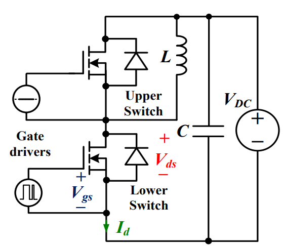 Discovering New and Advanced Methodology for Determining the Dynamic Characterization of Wide Bandgap DevicesSaumitra Jagdale15 March 20242369
For a long era, silicon has stood out as the primary material for fabricating electronic devices due to its affordability, moderate efficiency, and performance capabilities. Despite its widespread use, silicon faces several limitations that render it unsuitable for applications involving high power and elevated temperatures. As technological advancements continue and the industry demands enhanced efficiency from devices, these limitations become increasingly vivid. In the quest for electronic devices that are more potent, efficient, and compact, wide bandgap materials are emerging as a dominant player. Their superiority over silicon in crucial aspects such as efficiency, higher junction temperatures, power density, thinner drift regions, and faster switching speeds positions them as the preferred materials for the future of power electronics.
Read More A Comprehensive Guide to FPGA Development BoardsUTMEL11 September 20259784
This comprehensive guide will take you on a journey through the fascinating world of FPGA development boards. We’ll explore what they are, how they differ from microcontrollers, and most importantly, how to choose the perfect board for your needs. Whether you’re a seasoned engineer or a curious hobbyist, prepare to unlock new possibilities in hardware design and accelerate your projects. We’ll cover everything from budget-friendly options to specialized boards for image processing, delve into popular learning paths, and even provide insights into essential software like Vivado. By the end of this article, you’ll have a clear roadmap to navigate the FPGA landscape and make informed decisions for your next groundbreaking endeavor.
Read More Applications of FPGAs in Artificial Intelligence: A Comprehensive GuideUTMEL29 August 20252527
This comprehensive guide explores FPGAs as powerful AI accelerators that offer distinct advantages over traditional GPUs and CPUs. FPGAs provide reconfigurable hardware that can be customized for specific AI workloads, delivering superior energy efficiency, ultra-low latency, and deterministic performance—particularly valuable for edge AI applications. While GPUs excel at parallel processing for training, FPGAs shine in inference tasks through their adaptability and power optimization. The document covers practical implementation challenges, including development complexity and resource constraints, while highlighting solutions like High-Level Synthesis tools and vendor-specific AI development suites from Intel and AMD/Xilinx. Real-world applications span telecommunications, healthcare, autonomous vehicles, and financial services, demonstrating FPGAs' versatility in mission-critical systems requiring real-time processing and minimal power consumption.
Read More 800G Optical Transceivers: The Guide for AI Data CentersUTMEL24 December 20251569
The complete guide to 800G Optical Transceiver standards (QSFP-DD vs. OSFP). Overcome supply shortages and scale your AI data center with Utmel Electronic.
Read More Xilinx FPGAs: From Getting Started to Advanced Application DevelopmentUTMEL09 September 20253360
This guide is your comprehensive roadmap to understanding and mastering the world of Xilinx FPGA technology. From selecting your first board to deploying advanced AI applications, we'll cover everything you need to know to unlock the potential of these remarkable devices. The global FPGA market is on a significant growth trajectory, expected to expand from USD 8.37 billion in 2025 to USD 17.53 billion by 2035. This surge is fueled by the relentless demand for high-performance, adaptable computing in everything from 5G networks and data centers to autonomous vehicles and the Internet of Things (IoT). This guide will walk you through the key concepts, tools, and products in the Xilinx ecosystem, ensuring you're well-equipped to be a part of this technological revolution.
Read More
Subscribe to Utmel !
![KSZ8993ML]() KSZ8993ML
KSZ8993MLMicrochip Technology
![AT88SC0404CA-SH-T]() AT88SC0404CA-SH-T
AT88SC0404CA-SH-TMicrochip Technology
![ATECC508A-MAHDA-T]() ATECC508A-MAHDA-T
ATECC508A-MAHDA-TMicrochip Technology
![ATECC608A-SSHDA-T]() ATECC608A-SSHDA-T
ATECC608A-SSHDA-TMicrochip Technology
![HCS500-I/SM]() HCS500-I/SM
HCS500-I/SMMicrochip Technology
![AT88SC0404CA-SH]() AT88SC0404CA-SH
AT88SC0404CA-SHMicrochip Technology
![FSSD06BQX]() FSSD06BQX
FSSD06BQXON Semiconductor
![AD5522JSVDZ]() AD5522JSVDZ
AD5522JSVDZAnalog Devices Inc.
![HCS515-I/SL]() HCS515-I/SL
HCS515-I/SLMicrochip Technology
![AT88SC0104CA-SH-T]() AT88SC0104CA-SH-T
AT88SC0104CA-SH-TMicrochip Technology


