What is the Ripple of the Power Supply, How to Measure its Value, and How to Suppress it?
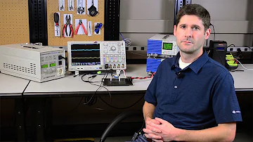
How to Measure Ripple & Noise in Power Supplies
| Topics covered in this article: |
| Ⅰ. How does Power Ripple Generate? |
| Ⅱ. What’s the Harm of Ripple? |
| Ⅲ. How to Measure Power Ripple? |
| Ⅳ. How to Suppress Ripple? |
Ⅰ. How does Power Ripple Generate?
Linear and switching power supplies are two types of power supplies that we commonly use. The AC voltage is rectified, filtered, and stabilized to produce the DC voltage they output. Because the filtering isn't good enough, clutter signals with periodic and random components end up on the DC level, causing ripples. The so-called ripple voltage is the peak value of the AC voltage in the output DC voltage in the situation of rated output voltage and current. Ripple is a multi-dimensional clutter signal. It's a periodic signal that varies up and down around the output DC voltage, but the period and amplitude aren't fixed, and the ripples of different power sources alter with time. In addition, the waveform is different.
Ⅱ. What’s the Harm of Ripple?
Ripple, in general, has a hundred drawbacks but no benefits. Ripple's key drawbacks are as follows:
a. The ripple carried in the power supply will generate harmonics on the electrical appliances, reducing the efficiency of the power supply;
b. Higher ripple may generate surge voltage or current, which may cause abnormal operation of electrical equipment or accelerate equipment aging;
c. Ripple in the digital circuit will interfere with the logical relationship of the circuit;
d. Ripple will also bring noise interference to communication, measurement and measurement instruments and meters, destroy the normal measurement and measurement of signals, and even damage the equipment.
As a result, when designing a power supply, we must keep the ripple below a few percent. We must consider reducing the ripple to a lesser value for devices with high ripple requirements.
The methods for measuring power supply ripple are usually classified into two categories: one for identifying a single power supply and the other for product debugging.
Indoors (about 20°C) is necessary for power supply identification in the power supply sector and by power users. The humidity should be less than 80%, and there should be minimum mechanical vibration and electromagnetic interference that affects the measurement. The standard instrument and the power supply that is being evaluated should both be above. Allow it to sit in the test environment for at least 24 hours.
When measuring power supply ripple for pure power supplies, it is necessary to do it during loading, and the load should be such that the output current exceeds 80% of the specified output current.
The necessary measurement standards must also be chosen for low-noise purely resistive or electronic loads. Different measurement standards will yield different results.
Ripple voltage can be stated in both absolute and relative terms. The ripple coefficient, or the ratio of the ripple voltage to the DC output voltage, is commonly used to evaluate the filtering performance of a DC power supply. The ripple coefficient is a critical metric for assessing DC power supplies. The percentage of the effective value of the ripple voltage to the DC output voltage is used to calculate it.
Ⅲ. How to Measure Power Ripple?
An oscilloscope is typically used to monitor power ripple, and there are three popular measurement methods:
1) Reliance on the connection method
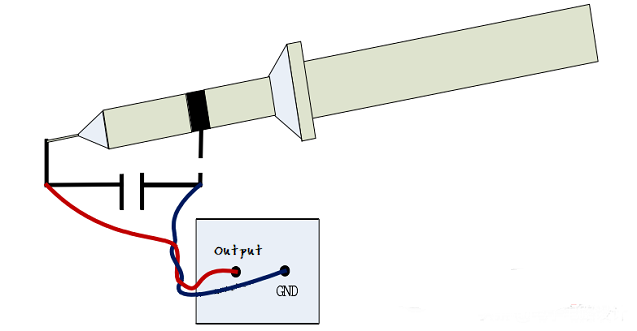
Touch the probe directly to the pin of the positive output, and the wire loop directly to the pin of the negative output, using an oscilloscope probe with a ground wire loop. This is due to the loop being set as short as possible, allowing the peak value read from the oscilloscope to represent the output Ripple and noise on the line. As seen in the diagram below
2) Direct method
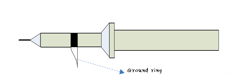
Connect the ground wire ring to the pin of the negative output and verify the output end with the probe ground ring.
3) Stranding method
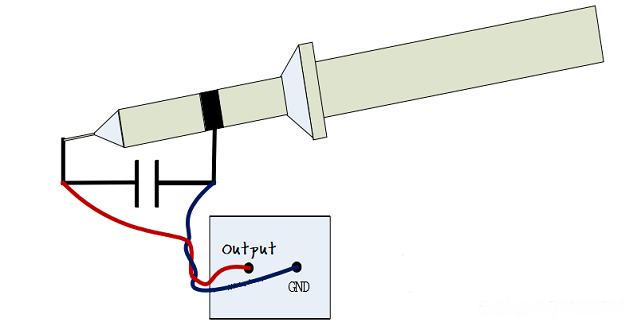
The output pin is linked to the twisted pair, which is then connected to the capacitor, and the capacitor's two ends are monitored with an oscilloscope.
When measuring ripple, keep the following in mind: It is vital to understand the ripple bandwidth's top limit. Because the ripple is low-frequency noise, it's best to use an oscilloscope that doesn't go too far beyond the ripple bandwidth's upper limit.
To decrease loop interference caused by the excessively long ground wire, switch on the oscilloscope's bandwidth limit function, set the bandwidth to 20MHz, and connect the shielding ground of the probe directly to the output ground.
To prevent boundary interference signals from entering the oscilloscope, connect a small ceramic capacitor and a small electrolytic capacitor in parallel at the probe access point.
Ⅳ. How to Suppress Ripple?
Low-frequency input ripple, high-frequency ripple, common-mode ripple noise induced by parasitic parameters, and ripple noise caused by closed-loop regulation control are the five main sources of power supply output ripple.
Increasing the capacitance of the filter circuit, utilizing an LC filter circuit, employing a multi-stage filter circuit, replacing the switching power supply with a linear power supply, and reasonable wiring are all common strategies for suppressing these waves. However, tailored interventions, according to its classification, can often accomplish twice the outcome with half the work.
1. Suppression of high-frequency ripple
High-frequency power conversion circuits are the primary source of high-frequency ripple noise. In high-frequency power conversion circuits, high-frequency power devices convert the input DC voltage, which is then rectified and filtered to provide a regulated output. High-frequency ripples with the same frequency as the switching working frequency are common, and they influence the external circuit. The output filter's form and settings are largely determined by the switching frequency of the switching power source. The power converter's working frequency is increased as much as possible in the design to lessen the filtering needs for high-frequency switching ripple.
2. Suppression of low-frequency ripple
The size of the filter capacitor in the output circuit determines the size of the low-frequency ripple. The capacitor's capacity can't be expanded endlessly, which means the output will always have residual low-frequency ripple. The AC ripple is output after being attenuated by the DC/DC conversion circuit, and its size is regulated by the gain of the control system and the DC/DC conversion circuit, which belongs to the low-frequency noise band. Because current-type and voltage-type control DC/DC conversion circuits have low ripple suppression capabilities and huge low-frequency AC ripples at their output end. To achieve a low-ripple output of the power supply, filtering methods for the low-frequency power supply ripple must be taken.
For some power supplies, the DC/DC converter's closed-loop gain circuit can be raised, and the pre-regulator circuit can be utilized to improve the ripple suppression effect, which can be done by changing the rectifier filter's capacitance and tweaking the feedback loop's parameters. Low-frequency ripple suppression.
3. Suppression of common-mode ripple
Switching power supplies are prone to common mode ripple noise. The parasitic capacitance and inductance in the wire between the power device and the heat sink base plate, as well as the primary and secondary sides of the transformer, interact with the rectangular wave voltage of the switching power supply when it acts on the power device. Make ripple noise in the common mode. The following are the ways for suppressing common-mode ripple noise:
1) Add a common-mode suppression inductance and capacitance at the output end to reduce parasitic capacitance between the control power device, the transformer, and the chassis ground;
2) Use EMI filters to effectively suppress common mode ripple interference;
3) Reduce the amplitude of switch glitches.
4. Suppression of closed-loop control loop ripple
The ripple in a closed-loop control loop is usually caused by incorrect parameter sets in the loop. The feedback network feeds the fluctuating voltage at the output end to the regulator loop when there is a particular fluctuation at the output end, causing the regulator to create a self-excited response. Additional ripple should be generated.
Suppression of the regulator's self-excited response, appropriate loop amplification selection, regulator stability, and LDO filtering at the power supply output end are the key suppression approaches. This is the most effective method for reducing noise and ripple.
1. How to eliminate power ripple?
Connect 103, 102, 104 ceramic capacitors in parallel to the ground at the output port. The smaller the capacitance value, the higher the frequency of the ripple filtered out. You can also consider connecting magnetic beads in series with the output port, and then output, but if you have a DC-DC module behind the power supply, you have to use magnetic beads with caution, because the magnetic beads may be a certain specification of DC-DC module that does not work properly.
2. What is the general output ripple of the switching power supply?
The output ripple is below 200mV to 50mV, and the full load cannot exceed this range.
3. How to distinguish the ripple and noise of the power supply output?
It can be judged by the observation of an oscilloscope. The ripple is generally synchronized with the switching frequency of the power supply, and the frequency of the noise is relatively high.
 LLC Converter with Planar Matrix Transformer for High-Current-High-Power ApplicationsSaumitra Jagdale15 March 20242911
The rise of data centres in recent years, driven by cloud computing and big data, has caused a significant increase in electricity consumption. In the United States alone, it exceeded 70 billion kWh by 2014, making up 1.8% of total national electricity usage.
Read More Enhancing Frequency Stability in Modern Distributed Power SystemsRakesh Kumar, Ph.D.21 September 20242546
The article discusses the importance of primary frequency regulation in maintaining grid stability. It also explores battery energy storage systems, virtual synchronous generators, and advanced control strategies to enhance frequency stability in power systems.
Read More The Impact of SMPS on LED Lighting and Diverse IndustriesUTMEL05 June 2025759
Switched-Mode Power Supplies (SMPS) enhance LED lighting and industries by improving energy efficiency, reliability, and sustainability across diverse applications.
Read More What is Uninterruptible Power Supply (UPS)?UTMEL08 April 20214775
UPS is an uninterruptible power supply containing the energy storage device. It is mainly used to give a part of a device with a higher power stability, providing uninterrupted power supplies.
Read More Switch-mode Power Supply BasicsUTMEL14 December 20206025
Switched-mode Power Supply (SMPS), also known as switching converter, is a high-frequency electric energy conversion device and a type of power supply. Its function is to convert a level of voltage into the voltage or current required by the user through different forms of architecture.
Read More
Subscribe to Utmel !
![JVN1AF-12V-F]() JVN1AF-12V-F
JVN1AF-12V-FPanasonic Electric Works
![ADW1103W]() ADW1103W
ADW1103WPanasonic Electric Works
![JQ1-24V-F]() JQ1-24V-F
JQ1-24V-FPanasonic Electric Works
![RJ1S-C-A24]() RJ1S-C-A24
RJ1S-C-A24IDEC
![2967235]() 2967235
2967235Phoenix Contact
![9290-05-00]() 9290-05-00
9290-05-00Coto Technology
![JW1AFSN-DC12V-F]() JW1AFSN-DC12V-F
JW1AFSN-DC12V-FPanasonic Electric Works
![G6RL-1-ASI-DC24]() G6RL-1-ASI-DC24
G6RL-1-ASI-DC24Omron Electronics Inc-EMC Div
![RJ2S-CL-D12]() RJ2S-CL-D12
RJ2S-CL-D12IDEC
![2903297]() 2903297
2903297Phoenix Contact


