
 Product
 Brand
Brand Articles
 Tools
Tools
Characteristics, Types, and Functions of Electrolytic Capacitors

What is a electrolytic capacitor?
Non-polar (bipolar) electrolytic capacitors adopt a dual oxide film structure, which is similar to two polar electrolytic capacitors that are formed by connecting two negative electrodes (cathodes). Their two electrodes are two metal plates (both with an oxide film), with the electrolyte in the middle of the two sets of oxide films. Polarized electrolytic capacitors are typically used for power filtering, decoupling, signal coupling, time constant setting, and DC blocking in power circuits or intermediate and low-frequency circuits. Non-polar electrolytic capacitors are commonly used in audio frequency divider circuits, television correction circuits, and starter circuits for single-phase motors.
Catalog
I Characteristics
1. Working Voltage

Figure 1. Electrolytic capacitor
The working voltage of electrolytic capacitors typically ranges from 4V, 6.3V, 10V, 16V, 25V, 35V, 50V, 63V, 80V, 100V, 160V, 200V, 300V, 400V, 450V, up to 500V, with specialized types available up to 630V or higher. The operating temperature range is typically -40°C to +105°C (with some high-performance types rated to +125°C). Electrolytic capacitors are characterized by large capacity, relatively large volume, and polarity. They are generally used for filtering and rectifying in DC circuits. At present, the most commonly used electrolytic capacitors are aluminum electrolytic capacitors and tantalum electrolytic capacitors. It is important to note that tantalum capacitors are indeed a type of electrolytic capacitor, despite common misconceptions. Both aluminum and tantalum capacitors belong to the electrolytic capacitor family.
2. Nominal Capacitance and Allowable Deviation
Nominal capacitance is the capacitance marked on the capacitor. The basic unit of capacitance is the farad (F), but this unit is too large and is rarely used in field labeling.
The relationship between other units is as follows:
1F = 1000mF
1mF = 1000μF
1μF = 1000nF
1nF = 1000pF
The deviation between the actual capacitance of the capacitor and the nominal capacitance is called the tolerance, and the accuracy is within the allowable deviation range.
Correspondence between accuracy level and allowable tolerance: 00 (01)-±1%, 0 (02)-±2%, Ⅰ-±5%, Ⅱ-±10%, Ⅲ-±20%, Ⅳ-(+20% -10%), Ⅴ-(+50% -20%), Ⅵ-(+50% -30%)
General capacitors are usually Ⅰ, Ⅱ, Ⅲ grade, while electrolytic capacitors are typically Ⅳ, Ⅴ, Ⅵ grade, selected according to use.
3. Rated Voltage
The rated voltage is the maximum DC voltage that can be continuously applied to the capacitor at the rated ambient temperature, generally directly marked on the capacitor case. If the operating voltage exceeds the capacitor's rated voltage, the capacitor will break down, causing permanent damage that cannot be repaired. For optimal reliability and longevity, it is recommended to operate electrolytic capacitors at 50-80% of their rated voltage. Operating capacitors near their maximum rated voltage can significantly reduce their lifespan and increase leakage current.
4. Insulation Resistance
When DC voltage is added to the capacitor, leakage current is generated. The ratio between the two is called insulation resistance.
When the capacitance is small, it mainly depends on the surface state of the capacitor. When the capacitance is greater than 0.1μF, it mainly depends on the performance of the dielectric. The larger the insulation resistance, the better.
Capacitor time constant: To properly evaluate the insulation of large-capacity capacitors, a time constant is introduced, which is equal to the product of the capacitor's insulation resistance and capacity.
5. Loss
Under the action of an electric field, the energy consumed by a capacitor due to heating in a unit time is called loss. All types of capacitors have specified their allowable losses in a certain frequency range. The losses of capacitors are mainly caused by dielectric loss, conductivity loss, and resistance of all metal parts of the capacitor.
Under the action of a DC electric field, the loss of a capacitor exists in the form of leakage loss, which is generally small. Under the action of an alternating electric field, the loss of the capacitor is not only related to the leakage conductance, but also the periodic polarization establishment process.
II Aluminum Electrolytic Capacitors
1. Structural Characteristics of Aluminum Electrolytic Capacitors:
The aluminum case and the plastic cover are sealed to form an electrolytic capacitor. Compared with other types of capacitors, aluminum electrolytic capacitors have the following obvious characteristics in structure:
(1) The working medium of aluminum electrolytic capacitors is produced by creating a thin layer of aluminum oxide (Al₂O₃) on the surface of aluminum foil by anodization. This oxide dielectric layer and the anode of the capacitor are combined into a complete system. They are interdependent and cannot be independent of each other.
(2) The anode of an aluminum electrolytic capacitor is an aluminum foil that generates an Al₂O₃ dielectric layer on the surface. The cathode is not the negative foil as commonly assumed, but rather the electrolytic solution of the capacitor.
(3) The negative foil plays the role of electrical extraction in the electrolytic capacitor because the electrolyte used as the cathode of the electrolytic capacitor cannot be directly connected to the external circuit, and an electrical path must be formed through another metal electrode and other parts of the circuit.
(4) The anode aluminum foil and cathode aluminum foil of aluminum electrolytic capacitors are usually etched aluminum foils, and the actual surface area is much larger than their apparent surface area. This is one reason why aluminum electrolytic capacitors usually have large capacitance. Due to the use of aluminum foil with numerous micro-etched pores, a liquid electrolyte is usually required to more effectively utilize its actual electrode area. The etched surface can increase capacitance by a factor of up to 200 compared to a smooth surface.
(5) Since the dielectric oxide film of the aluminum electrolytic capacitor is obtained by anodizing, and its thickness is proportional to the voltage applied by the anodizing, in principle, the thickness of the dielectric layer of the aluminum electrolytic capacitor can be artificially and precisely controlled. The dielectric thickness is approximately 1.4 nanometers per volt of forming voltage.
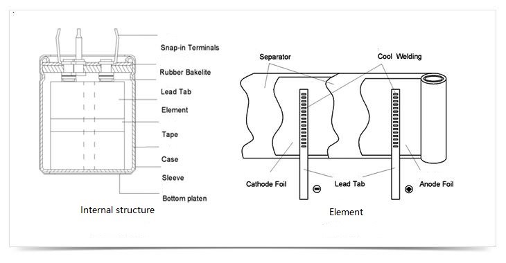
Figure 2. The internal structure of the aluminum electrolytic capacitor
As the figure shows, the positive electrode and the negative electrode are wound according to their central axes to form the core of an aluminum electrolytic capacitor. The core is placed in an aluminum case to package the aluminum electrolytic capacitor. To keep the electrolyte solution from leaking and drying up, the opening of the aluminum case of the electrolytic capacitor package is sealed with a rubber plug. To obtain a large capacitance and a small volume, the surface of the positive aluminum foil is chemically etched to form an uneven surface, which increases the surface area of the electrode, thereby increasing the capacitance.
The reason why aluminum electrolytic capacitors have polarity is that the aluminum oxide film on the positive electrode plate has unidirectional conductivity. Only when the positive electrode of the capacitor is connected to the positive electrode of the power supply and the negative electrode is connected to the negative electrode of the power supply can the aluminum oxide film serve as an insulating medium. If the polarity of the aluminum electrolytic capacitor is reversed, the aluminum oxide film becomes a conductor, and the electrolytic capacitor not only fails to function but also causes a large current to pass through, causing damage to the capacitor and potentially resulting in catastrophic failure, fire, or explosion.
To prevent the accidental explosion of aluminum electrolytic capacitors during use, mechanical grooves are generally pressed on the end face of the aluminum casing package. Once the internal pressure of the electrolytic capacitor is too high, the grooves at these weak points will rupture and release the pressure, providing explosion protection.
Although aluminum electrolytic capacitors have polarity, if a special construction is used with two anodes connected in series (back-to-back configuration), non-polar electrolytic capacitors can also be made.
2. Advantages of Aluminum Electrolytic Capacitors
Compared with other types of capacitors, the advantages of aluminum electrolytic capacitors are shown in the following aspects:
(1) The capacitance per unit volume is particularly large. The lower the operating voltage, the more prominent this feature is. Therefore, it is particularly suitable for miniaturization and large capacity of capacitors. For example, the specific capacity of the CD26 low-voltage large-capacity aluminum electrolytic capacitor is about 300 μF/cm³, while the specific capacity of other low-voltage chip ceramic capacitors, which are also characterized by miniaturization, is generally not more than 2 μF/cm³.
(2) Aluminum electrolytic capacitors have "self-healing" characteristics during the working process. The so-called "self-healing" characteristic means that the defects or deficiencies in the dielectric oxide film can be repaired at any time during the capacitor's working process, recovering the insulation capacity it should have, and avoiding avalanche breakdown of the dielectric.
(3) The dielectric oxide film of aluminum electrolytic capacitors can withstand very high electric field strength. During the operation of aluminum electrolytic capacitors, the electric field strength of the dielectric oxide film is about 600kV/mm, which is more than 30 times that of paper dielectric capacitors.
(4) High-rated electrostatic capacity can be obtained. Low-voltage aluminum electrolytic capacitors can easily obtain electrostatic capacitances of thousands or even tens of thousands of microfarads. Capacitance values commonly range from 1μF to over 100,000μF, with modern designs pushing these limits even further.
3. Disadvantages of Aluminum Electrolytic Capacitors
(1) Poor insulation performance. It can be said that aluminum electrolytic capacitors have the worst insulation performance among all types of capacitors. For aluminum electrolytic capacitors, leakage current is usually used to characterize its insulation performance. The leakage current of high-voltage and large-capacity aluminum electrolytic capacitors can reach less than 1mA.
(2) The loss factor is large. The dissipation factor (DF) of a low-voltage aluminum electrolytic capacitor is usually above 10%, significantly higher than ceramic or film capacitors.
(3) The temperature characteristics and frequency characteristics of aluminum electrolytic capacitors are poor compared to other capacitor types. Performance can degrade significantly at temperature extremes and high frequencies.
(4) Aluminum electrolytic capacitors have polarity. When used in electronic circuits, the anode of an aluminum electrolytic capacitor must be connected to a point with a high potential in the circuit, and the cathode to a point with a low potential to perform its electrical function normally. If the connection is reversed, the leakage current of the capacitor will increase sharply, and the core will be seriously heated, which will cause the capacitor to fail, and may explode and damage other components on the circuit board.
(5) There is a practical upper limit for the working voltage. According to the special generation method of the aluminum electrolytic capacitor dielectric oxide film, the maximum working voltage for standard types is generally 500V to 630V, and its development potential is limited beyond these voltages. For other non-electrolytic capacitors, as long as the dielectric thickness is appropriately increased, the theoretical working voltage can reach higher limits.
(6) The performance of aluminum electrolytic capacitors is liable to deteriorate over time, particularly when stored without voltage applied. When using aluminum electrolytic capacitors that have been stored for a long time, the rated operating voltage should not be applied suddenly but should be gradually increased to the rated voltage through a process called "reforming."
(7) Because the traditional aluminum electrolytic capacitor uses the electrolytic solution as a cathode, there is a significant obstacle in chip formation. Its chip formation process lags behind ceramic capacitors and metalized film capacitors, although modern surface-mount aluminum electrolytic capacitors have addressed many of these challenges.
III Uses of Electrolytic Capacitors
1. DC Blocking: The role is to prevent DC from passing and allow AC to pass.
2. Bypass (Decoupling): Provides a low-impedance path for some parallel components in an AC circuit, effectively shunting unwanted AC signals to ground.
3. Coupling: As a connection between two circuits, allowing AC signals to pass through and be transmitted to the next stage circuit while blocking DC components.
4. Filtering: This is very important in power supply design. The capacitors smooth out voltage ripples and provide stable DC output.
5. Temperature Compensation: To compensate for the influence of other components' inadequate temperature adaptability, compensation is performed to improve the stability of the circuit.
6. Timing: The capacitor and resistor are used together to determine the time constant of the circuit. The time constant t = RC.
7. Tuning: System tuning of frequency-related circuits, such as mobile phones, radios, and televisions.
8. Rectification Support: Works with rectifier circuits to smooth pulsating DC output from AC sources.
9. Energy Storage: Stores electrical energy for release when necessary, such as camera flash, heating equipment, motor starting applications, and power backup systems.
IV Types of Electrolytic Capacitors
According to analysis and statistics, electrolytic capacitor package types are mainly divided into the following categories:
1. Divided into three categories according to structure: fixed capacitors, variable capacitors, and trimmer capacitors.
2. Classified by dielectric: organic dielectric capacitors, inorganic dielectric capacitors, electrolytic capacitors, and air dielectric capacitors.
3. According to the purpose: high-frequency bypass, low-frequency bypass, filtering, tuning, high-frequency coupling, low-frequency coupling, and small capacitors.
4. According to the manufacturing materials, it can be divided into ceramic capacitors, polyester capacitors, electrolytic capacitors (both aluminum and tantalum types), and advanced polypropylene capacitors.
5. High-frequency bypass: ceramic capacitors, mica capacitors, glass film capacitors, polyester capacitors, glass glaze capacitors.
6. Low-frequency bypass: paper dielectric capacitors, ceramic capacitors, aluminum electrolytic capacitors, polyester capacitors.
7. Filtering: aluminum electrolytic capacitors, paper capacitors, composite paper capacitors, liquid tantalum capacitors.
8. Tuning: ceramic capacitors, mica capacitors, glass film capacitors, polystyrene capacitors.
9. Low-frequency coupling: paper dielectric capacitors, ceramic capacitors, aluminum electrolytic capacitors, polyester capacitors, solid tantalum capacitors.
10. Small capacitors: metalized paper capacitors, ceramic capacitors, aluminum electrolytic capacitors, polystyrene capacitors, solid tantalum capacitors, glass glaze capacitors, metalized polyester capacitors, polypropylene capacitors, mica capacitors.
Note on Tantalum Capacitors: Tantalum electrolytic capacitors are indeed a type of electrolytic capacitor, using tantalum metal for the anode and tantalum pentoxide as the dielectric. They offer higher capacitance density, lower ESR (Equivalent Series Resistance), better frequency response, and superior stability compared to aluminum electrolytic capacitors. However, they are more expensive and have a lower maximum voltage rating (typically limited to 50V or less for common types). Tantalum capacitors are particularly popular in surface mount applications and are extensively used in portable electronics, medical devices, aerospace, and military applications. About 80% of tantalum electrolytic capacitors are manufactured in surface mount device (SMD) form.
V Polarity Discrimination of Electrolytic Capacitors
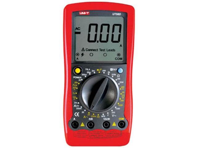
Figure 3. A multimeter
If you do not know the polarity of electrolytic capacitors, the multimeter's resistance range can be used to measure the polarity of electrolytic capacitors. It is best to use R×100 or R×1K range when measuring.
We know that only when the positive end of the electrolytic capacitor is connected to the positive power supply (black test lead when using resistance measurement) and the negative end is connected to the negative power supply (red test lead when using resistance measurement), the leakage current of the electrolytic capacitor is small (large leakage resistance). On the contrary, the leakage current of the electrolytic capacitor increases (the leakage resistance decreases).
When measuring, first assume that a certain "+" pole is connected to the black test lead of the multimeter, and the other electrode is connected to the red test lead of the multimeter. Note the stopping scale of the meter hand (the left-hand value of the hand represents higher resistance), and then discharge the capacitor (touch both leads together). Reverse the two test leads and repeat the measurement. In the two measurements, the time when the meter hand stays furthest to the left (highest resistance value) indicates that the black test lead is connected to the positive electrode of the electrolytic capacitor.
Article Recommended:
 UTMEL
UTMEL
We are the professional distributor of electronic components, providing a large variety of products to save you a lot of time, effort, and cost with our efficient self-customized service. careful order preparation fast delivery service
1.What is the use of electrolytic capacitor?
Smoothing the input and output to a filter. Noise filtering or decoupling in power supplies. Coupling signals between amplifier stages. Storing energy in low power applications.
2.How do electrolytic capacitors work?
Like other conventional capacitors, electrolytic capacitors store the electric energy statically by charge separation in an electric field in the dielectric oxide layer between two electrodes. The non-solid or solid electrolyte in principle is the cathode, which thus forms the second electrode of the capacitor.
3.What is the difference between electrolytic and non electrolytic capacitor?
An electrolytic capacitor is unipolar due to the electrolyte just like a battery. A non-electrolytic is bi-polar as it consists of a dielectric material and not an electrolyte.
4.Are electrolytic capacitor AC or DC?
Because electrolytic capacitor is in fact used with DC. For AC, there are special kind of electrolytic capacitors.
5.What is the main disadvantage of electrolytic capacitors?
Along with the obvious danger of explosion, the main disadvantage to using aluminum electrolytic capacitors is the likelihood of dry-out. Essentially, when the capacitor is not in use, it will start to decrease the dielectric on the anode foil.
 What is Feedthrough Capacitor?UTMEL06 November 202140557
Hello, everyone. I am Rose. Today I will introduce the feedthrough capacitor to you. The feedthrough capacitor is a three-terminal capacitor that is used to reduce high frequencies. The feedthrough capacitor, unlike regular three-terminal capacitors, is directly installed on the metal panel, resulting in a lower grounding inductance and a negligible effect on the lead inductance.
Read More Detailed Explanation About Twenty Kinds of CapacitorUTMEL08 November 20218971
Hello everyone, I am Rose. Today I will introduce 20 kinds of capacitor to you. I will illustrate them in three or four aspects: Structure, features, Usages, advantages and disadvantages.
Read More What is a Polypropylene Capacitor?UTMEL08 November 202120958
A polypropylene capacitor is a kind of capacitor with a very stable electric capacity. It is often used in applications requiring very precise capacitance and can replace most polyphenylene or mica capacitors.
Read More What is the Difference between MOM, MIM and MOS Capacitors?UTMEL17 April 202567972
This article mainly introduces the structure, principle, advantages and disadvantages of MOM, MIM and MOS capacitors and the difference between them.
Read More What is a Power Capacitor?UTMEL20 November 20216261
Power capacitors are capacitors used in power systems and electrical equipment. Any two pieces of metal conductors are separated by an insulating medium to form a capacitor. The size of the capacitor is determined by its size and the characteristics of the insulating medium between the two plates.
Read More
Subscribe to Utmel !
![EVAL-RHF1009A]() EVAL-RHF1009A
EVAL-RHF1009ASTMicroelectronics
![SR1550NA]() SR1550NA
SR1550NAIntel
![DK-V7-VC709-G]()
![LX2208 EVAL KIT]() LX2208 EVAL KIT
LX2208 EVAL KITMicrochip
![THEVAF84C]() THEVAF84C
THEVAF84CTHine
![MAX1672EVKIT]() MAX1672EVKIT
MAX1672EVKITAnalog Devices
![MAX24310EVKIT#]() MAX24310EVKIT#
MAX24310EVKIT#Microchip
![MAX77975EVKIT#]() MAX77975EVKIT#
MAX77975EVKIT#Maxim
![ADM00831]() ADM00831
ADM00831Microchip
![BMP86D100FF0A]() BMP86D100FF0A
BMP86D100FF0AToshiba
