Aluminum Electrolytic Capacitor Basis: Definition, Characteristics and Life

Inside An aluminum electrolytic capacitor || Let's See Inside || as fast as possible
Ⅰ. Introduction
Aluminum electrolytic capacitors are made up of a negative electrode made of an aluminum cylinder that is filled with liquid electrolyte and put into a positive electrode formed of a bent aluminum strip. It must also be exposed to DC voltage in order to develop an oxide film on the positive plate, which will serve as a medium. It is useful for power supply filtering or low-frequency circuits and has a big capacity but high leakage, poor stability, positive and negative polarity. Do not invert the positive and negative poles when utilizing. Aluminum electrolytic capacitors, along with ceramic capacitors, are the most extensively used capacitor kinds today.
Ⅱ. Overview of aluminum electrolytic capacitors
2.1 The basic model
Capacitors are components that are not active. Aluminum electrolytic capacitors have a higher CV value and are less expensive than other capacitors of the same size across the board. The image depicts the fundamental model of a capacitor.
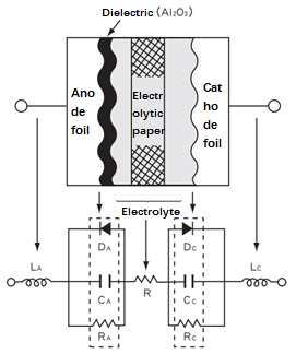
Figure. 1
The electrostatic capacity is calculated using the following formula:

Figure. 2
The dielectric constant is one of them, as is S, which is the surface area facing the two-pole plate, and d, which is the distance between the two-pole plates (dielectric thickness).
The electrostatic capacity is proportional to the dielectric constant, the electrode plate surface area, and inversely proportional to the distance between the two electrode plates, as shown in the formula. The dielectric constant of the dielectric oxide layer (Al2O3) used in aluminum electrolytic capacitors is typically 810, which is comparable to other capacitor types. The surface area of the aluminum foil is increased by etching it, and the electrochemical treatment is employed to make the film thinner. Aluminum electrolytic capacitors can reach higher CV values per unit area than other capacitors thanks to an oxidized dielectric layer with a greater withstand voltage.
The following are the key components of aluminum electrolytic capacitors:
Aluminum foil as anode
On the surface of the anode aluminum foil, a dielectric —- oxide coating (Al2O3) is generated.
Cathode - The electrolyte is the true cathode.
Electrolytic paper soaked with electrolyte and cathode foil connected to the electrolyte are two other components, Aluminum electrolytic capacitors, in summary, are polar, asymmetrically built devices. A bipolar (non-polar) capacitor with both electrode s made of anodized aluminum foil.
2.2 The basic structure
The graphic depicts the structure of an aluminum electrolytic capacitor element. The anode foil, electrolytic paper, cathode foil, and terminals (internal and external terminals) are twisted together and impregnated with electrolyte before being placed into an aluminum box and sealed with rubber.

Figure. 3
2.3 Material properties
Aluminum electrolytic capacitors are made primarily of aluminum foil. The anode is made of aluminum foil. An oxide coating (Al2O3) will form on the surface of the aluminum foil after it has been activated in the electrolyte. This oxide layer has a dielectric function.
After the oxide coating is produced, the aluminum foil becomes a metal with rectifying properties in the electrolyte, similar to a diode, and is referred to as a valve metal.
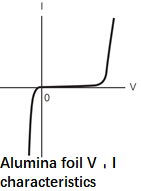
Figure. 4
①Anode aluminum foil
To begin, the aluminum foil material was electrochemically etched in an aqueous chloride solution to increase the surface area. After that, a dielectric oxide layer (Al2O3) is created on the surface of the aluminum foil after applying a voltage higher than the rated voltage in the ammonium borate solution.
②Cathode aluminum foil
The cathode aluminum foil, like the anode foil, goes through an etching process but not an oxidation process. As a result, the surface of the cathode aluminum foil has only a small amount of natural oxidation (Al2O3), and the voltage that can be tolerated is only about 0.5V.
③ Electrolyte
The electrolyte is an ionically conductive liquid that serves as the true cathode, connecting the dielectric layer on the anode aluminum foil's surface. To connect the true cathode and the internal circuit, the cathode aluminum foil functions as a collector. The electrolyte is a fundamental component that determines the characteristics of a capacitor (temperature characteristics, frequency characteristics, service life, etc.).
④ Electrolytic paper
The electrolytic paper's primary function is to equalize the electrolyte distribution and maintain the distance between the cathode and anode foils.
2.4 The production process
① Etching (enlarges the surface area)
The etching process increases the surface area of the aluminum foil. In a chloride solution, etching is an electrochemical process in which alternating or direct current is delivered.
②Chemical formation (formation of dielectric layer)
The process of generating a dielectric layer (Al2O3) on the surface of the anode aluminum foil is known as formation. In most cases, the anode is manufactured aluminum foil.
③Cutting
According to the size requirements of different goods, cut the aluminum foil (cathode foil and anode foil) and electrolytic paper to the desired size.

Figure. 5
④Winding
In the winding process, the electrolytic paper is inserted between the cathode and anode foils, rolled into a cylindrical shape, and the cathode and anode foils are linked with terminals.
⑤Impregnation
The process of immersing an element in an electrolyte is known as immersion. The dielectric layer can be repaired further using the electrolyte.
⑥Seal
The process of placing an element into an aluminum box and sealing it with a sealing substance is known as sealing (rubber, rubber cover, etc.).
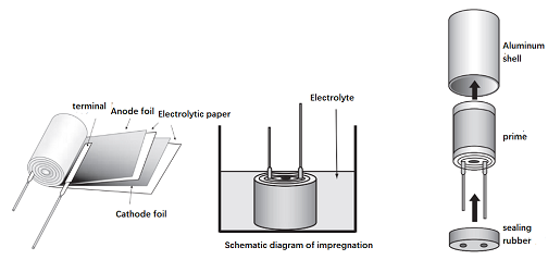
Figure. 6
⑦Aging (reforming)
The process of supplying a voltage to a sealed capacitor at a high temperature is known as aging. This procedure can help to heal some of the dielectric layer damage caused by the cutting and winding processes.
⑧Full inspection, packaging
All goods are tested for electrical characteristics after age. Also, perform terminal processing, tape, and other similar tasks. At the end, the packaging is completed.
Ⅲ. Basic Features
3.1 Electrostatic capacity
The greater the capacity, the larger the electrode surface area (the ability to store charge). The aluminum electrolytic capacitor's electrostatic capacitance value is the value measured at 20°C, 120Hz/0.5V under AC conditions.
① When the temperature rises, the capacity rises with it; when the temperature falls, the capacity falls with it.

Figure. 7
②The capacity is smaller the higher the frequency; the capacity is larger the lower the frequency.
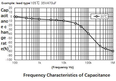
Figure. 8
3.2 Loss angle

Figure. 9
The electrolytic capacitor's analogous circuit is depicted in the diagram above (ignoring the insulation resistance). Because the frequency is so low in comparison to the equivalent series inductance L at 120Hz (the nominal loss angle of the general capacitor is measured at this frequency), it can be ignored. The loss angle model is as follows:
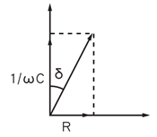
Figure. 10
The loss angle formula can be obtained:

Figure. 11
The graph below depicts the link between loss angle and temperature. The smaller the loss angle, the higher the temperature.
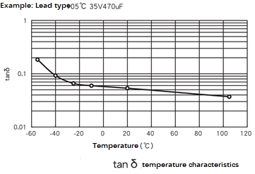
Figure. 12
The loss angle increases dramatically at low temperatures, reaching 0.05 at 20°C and 0.09 at -40°C. The ESR grows by approximately a factor of one, according to the formula.
3.3 Leakage current
Aluminum electrolytic capacitors have a leakage current as one of their properties. The dielectric oxide layer permits a tiny current to pass through when a DC voltage is applied. Leakage current refers to this portion of the tiny current. A capacitor that does not leak current is ideal (unlike charging current, which is constant even if the voltage is constant).
As illustrated, the leakage current varies with time and gradually reduces to attain a stable value. As a result, the leakage current specification value is the value measured after applying the rated voltage for a period of time at 20°C.
The leakage current increases as the temperature rises; when the temperature falls, the leakage current reduces. The applied voltage decreases, and the leakage current value also decreases.
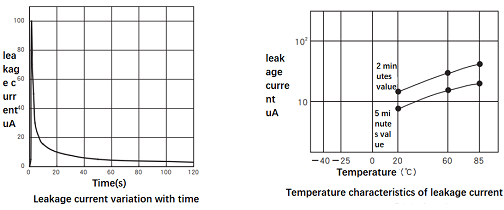
Figure. 13
3.4 Impedance-frequency curve
The capacitor's complex impedance, according to the model, is:

Figure. 14
The impedance's modulo value is:

Figure. 15
Draw the following impedance-frequency curve:
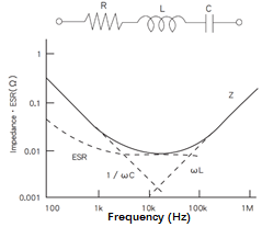
Figure. 16
The capacitive reactance is 1/C, and the downward angle of the capacitive reactance straight line in the figure forms a 45° angle. The inductive reactance, L, has a line that creates a 45° angle with the upper right corner. Equivalent Series Resistance is abbreviated as R. The frequency-dependent dielectric loss has a large influence in the low frequency band, hence the R curve slopes downward. Because the resistance of the electrolyte and electrolytic paper is dominant in the high frequency range and is no longer affected by frequency, the R value tends to be stable.
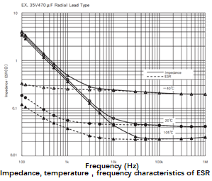
Figure. 17
Ⅳ. Common aluminum electrolytic capacitor parameters
Electrolytic capacitors with low ESR, extended life, and high temperature are available from a variety of manufacturers. The general product is the cheapest and has the lowest performance. 85°C/105°C-1000h/2000h are the general temperature and life parameters. This is the aluminum electrolytic capacitor that was mentioned before in this section.
4.1 ESR parameters
To begin with, most manufacturers will not explicitly provide the ESR value of typical aluminum electrolytic capacitors, instead providing the loss angle parameter, which is currently set at 120Hz (the loss angle is related to the frequency).
The parameters of the most common aluminum electrolytic capacitors, 100uF-16V, from several brands are listed below. The ESR value of 120Hz is computed using the method described above.
When the capacitance value and the rated voltage value are determined, it can be seen that the ESR of each manufacturer is not that different.
In addition, it can also be noted that changing packages (sizes) will not change the ESR too much, but will affect the size of the ripple current. The larger the size, the greater the heat resistance and ripple current.
So, what is the ESR of various capacities and voltages of aluminum electrolytic capacitors?
We can draw the following conclusions:
①The larger the capacity, the smaller the ESR value.
②The larger the rated voltage, the smaller the ESR value.
It should be noted that this ESR value is for a 120Hz frequency. The ESR will drop as the frequency rises. Looking at the last chapter's ESR and frequency curve, it lowers to about 1/2-1 of 120hz at 100Khz. /4 (this scale data is really poor) or so.
4.2 Rated ripple current
Aluminum electrolytic capacitors, unlike MLCC ceramic capacitors, must pay attention to the rated ripple current, which is an effective value that cannot be exceeded beyond the specification. Aluminum electrolytic capacitors have a relatively high ESR. As a result, if the ripple current is strong enough, the internal heating will be severe, causing the capacitor to fail. As a result, each product has a rated ripple current.
The smaller the ESR, the larger the rated ripple current.
The larger the package, the higher the rated ripple current.
Although some series reduce the ambient temperature to apply a ripple current greater than the rated value, the life will be shortened if the self-temperature rise T increases. At varied ambient temperatures, T has a stated limit value; please do not exceed the limit value during use.
The calculation formula of self-temperature rise △T is as follows:
Io: The rated ripple current Arms after using the frequency coefficient correction at the working upper limit temperature.
Ix: Ripple current Arms in actual use.
△To: Self-temperature rise when rated ripple current is superimposed.
Ordinary aluminum electrolytic capacitors have a nominal rated ripple current of 120Hz. What about other frequency' rated current ripple values? Manufacturers will typically include a ripple current frequency correction coefficient in their specifications.
For example, the Ruby 100UF-16V aluminum electrolytic capacitor's rated ripple current at 120Hz is 135mA; what is the rated ripple current at 10Khz?
The ripple current at 10KHz is Irms=135mA*1.2=162mA, as determined by looking up the correction coefficient in the table.
Ⅴ. High-quality aluminum electrolytic capacitors
High-quality aluminum electrolytic capacitors are contrasted to regular aluminum electrolytic capacitors in this article. Ordinary aluminum electrolytic capacitors are unable to suit our needs in rare circumstances. Aluminum electrolytic capacitor manufacturers often offer several series of models, with the highest-quality ones falling into three categories: high temperature resistance, extended life, and low impedance.
The high temperature can reach 125 °C, and the high life can exceed 5000 hours.
In this way, the ESR values of low-ESR aluminum electrolytic capacitors from different manufacturers of the same specification aren't that different, and they're all around one-seventh or eighth of the standard (120Hz), but if the frequency is 100Khz, the difference isn't as big, maybe half as much.
Ⅵ. Abnormal voltage
When an irregular voltage is applied to a capacitor, it heats up and produces gas, which causes the internal pressure to rise. The valve will open as the pressure rises, or the capacitor will be damaged and fail.
6.1 Excessive voltage
When a voltage is applied that is higher than the rated voltage, a chemical reaction occurs in the anode foil (forming a dielectric), resulting in a quick increase in leakage current, which generates heat and gas and so raises the internal pressure.
Increases in voltage, current, and ambient temperature will speed up this chemical reaction. The capacitor will open or fail as the internal pressure rises. It may also result in a reduction in capacitor capacity, an increase in loss angle, and leakage current, all of which can lead to the capacitor short-circuiting.
6.2 Reverse voltage
The application of reverse voltage causes a chemical reaction in the capacitor's cathode foil, resulting in a rapid increase in leakage current, similar to that caused by high voltage. Inside the capacitor, heat and gas will be created, and the internal pressure will rise.
With an increase in voltage, current, and ambient temperature, this chemical reaction will accelerate. The electrostatic capacity decreases, the loss angle increases, and the leakage current increases all at the same time.
A reverse voltage of about 1V causes a reduction in capacitance; a reverse voltage of 2V-3V causes a reduction in capacitance, an increase in loss angle, and/or an increase in leakage current, all of which shorten the capacitor's life. The valve will open or the capacitor will be damaged if a higher reverse voltage is applied.
Ⅶ. Restart voltage
The voltage between the two terminals will rise again after charging the aluminum electrolytic capacitor, short-circuiting its terminals, and leaving the short-circuit line open for a period of time. The restart voltage is the voltage at this point.
When a voltage is supplied to the dielectric, an electrical change happens inside the dielectric, and the applied voltage as well as positive and negative reverse charges are carried on the dielectric's surface. (Polarization) There is a speed variation due to polarization speed. Put the voltage between the terminals to 0V after applying a voltage, open the circuit, and position it, and the potential with delayed polarization response will provide a restart voltage between the terminals.
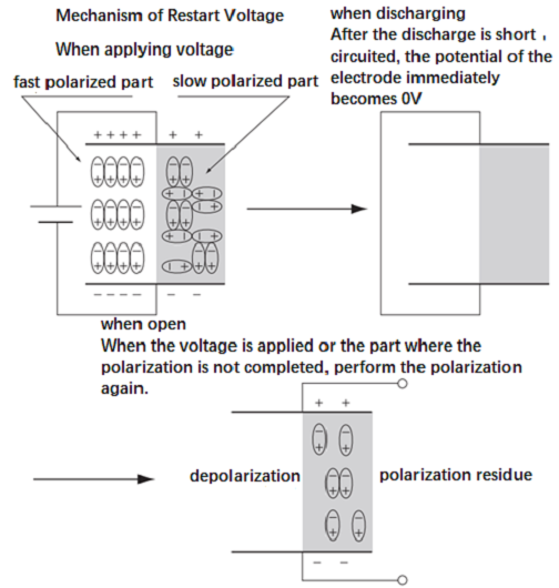
Figure. 18
The restart voltage's temporal change is depicted in the image, with the greatest value occurring roughly 10 to 20 days after the two terminals are opened, and then progressively decreasing. Furthermore, the value of the restart power of large-sized items (screw terminal type, board self-supporting type) is increasing.
If the two terminals are mistakenly short-circuited after the restart voltage is applied, the ignition will cause anxiety among the production line operators, and the low-voltage driving parts of the circuit, such as the CPU and memory, may be destroyed. Before using, discharge the accumulated charge with a resistance of 100 to 1K ohms as a precaution.
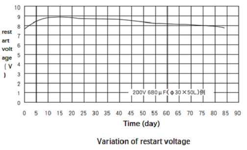
Figure. 19
Ⅷ. Life of aluminum electrolytic capacitors
8.1 Calculation principle of life
The electrolyte evaporating outward through the seal shortens the life of aluminum electrolytic capacitors, resulting in a decrease in electrostatic capacity and an increase in the loss tangent value.
The Arrhenius law describes the link between the electrolyte evaporation rate and temperature:

Figure. 20
k is: chemical reaction rate
A: Frequency factor
E: activation energy
R: gas constant
T: temperature
The rate of chemical reaction (the rate at which electrolyte is lost) is logarithmically proportional to temperature, according to this formula. The ambient temperature of the aluminum electrolytic capacitor and the ripple current determine the temperature. As a result, the service life of the aluminum electrolytic capacitor is determined by the ambient temperature and ripple current.
The following is the real service life formula for aluminum electrolytic capacitors (different capacitors vary, therefore use this as a guide only):

Figure. 21
Lx is the service life.
Lo is the guaranteed life value (life declared in the specification).
To is the maximum working temperature (the upper limit of temperature in the specification).
Tx is the actual ambient temperature, the actual ambient temperature of aluminum electrolytic capacitors.
It is easy to conclude that the life of the capacitor is doubled for every 10°C increase in the operating temperature of the capacitor.
1. What are the four characteristics of aluminum electrolytic capacitors?
Capacity CAP, loss tangent DF, equivalent series resistance ESR, leakage current LC.
2. What is the difference between aluminum electrolytic capacitors and tantalum capacitors?
The essential difference between aluminum electrolytic capacitors and tantalum capacitors is that the medium used is different. Aluminum electrolytic capacitors are wound with aluminum foil and contain electrolyte. Tantalum capacitors are made of tantalum and have no electrolyte. Therefore, tantalum capacitors have stable performance compared to aluminum electrolytic capacitors, but the cost is high and the price is expensive.
3. How to distinguish the positive and negative electrodes of aluminum electrolytic capacitors?
Most electrolytic capacitors have positive and negative electrodes (of course, there are also non-polar electrolytic capacitors). Electrolytic capacitors with long and short legs are divided into positive and negative electrodes. The long legs are positive and the short legs are negative. You can also see the shell logo, the one marked with a "-" or a thick line is the negative electrode.
 What is Feedthrough Capacitor?UTMEL06 November 202139018
Hello, everyone. I am Rose. Today I will introduce the feedthrough capacitor to you. The feedthrough capacitor is a three-terminal capacitor that is used to reduce high frequencies. The feedthrough capacitor, unlike regular three-terminal capacitors, is directly installed on the metal panel, resulting in a lower grounding inductance and a negligible effect on the lead inductance.
Read More Detailed Explanation About Twenty Kinds of CapacitorUTMEL08 November 20218171
Hello everyone, I am Rose. Today I will introduce 20 kinds of capacitor to you. I will illustrate them in three or four aspects: Structure, features, Usages, advantages and disadvantages.
Read More What is a Polypropylene Capacitor?UTMEL08 November 202119846
A polypropylene capacitor is a kind of capacitor with a very stable electric capacity. It is often used in applications requiring very precise capacitance and can replace most polyphenylene or mica capacitors.
Read More What is the Difference between MOM, MIM and MOS Capacitors?UTMEL17 April 202563697
This article mainly introduces the structure, principle, advantages and disadvantages of MOM, MIM and MOS capacitors and the difference between them.
Read More What is a Power Capacitor?UTMEL20 November 20215723
Power capacitors are capacitors used in power systems and electrical equipment. Any two pieces of metal conductors are separated by an insulating medium to form a capacitor. The size of the capacitor is determined by its size and the characteristics of the insulating medium between the two plates.
Read More
Subscribe to Utmel !


