An Overview of Supercapacitors
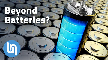
Supercapacitors explained - the future of energy storage?
Catalog
2. Identification of Electric Double-Layer and Electrochemical Supercapacitors | |
3. Supercapacitors in the Development of New Energy Vehicles | |
I Introduction
In brief, a supercapacitor (also called an ultracapacitor) is a high-capacitance, polarized electrolytic device. “High” here refers to capacitance (farads), not necessarily physical size.
For ordinary electrolytic capacitors, larger capacitance and voltage ratings generally require larger packages. Electrolytic capacitors typically provide capacitance values from microfarads up to several thousand microfarads (and some specialized types approach 1F) with voltage ratings up to hundreds of volts. As voltage rating rises, available capacitance per volume usually falls.
Supercapacitors follow similar size trends, but they operate in a different regime. Typical single-cell electric double-layer capacitors (EDLCs) have capacitances ranging from a few farads to several thousand farads, with single-cell rated voltages commonly 2.3–3.0 V (organic electrolytes). Multiple cells are placed in series to reach higher system voltages (tens to hundreds of volts) with balancing circuitry. As capacitance and system voltage increase, volume also increases.
Early supercapacitors with tens of farads were mainly used in high-power supplies and industrial modules. Today, compact low-voltage EDLCs and lithium-ion capacitors (LICs) appear in consumer and IoT devices for short-term backup, peak-power assist, real-time clocks, and energy harvesting buffers.
Although supercapacitors and electrolytic capacitors look similar, their electrical behavior differs substantially. For example, a common 10 µF, 25 V electrolytic capacitor can be similar in size to a 1–10 F, 2.7 V EDLC. With recent advances, multi-cell supercapacitor modules can achieve 16–160 V (and higher) with integrated protection and balancing, but each individual EDLC cell remains limited to a few volts.
Inside Look Of A Supercapacitor vs Electrolytic Capacitor
II Structure of Supercapacitors
In principle, a supercapacitor stores charge electrostatically and (for some types) through fast, reversible surface redox reactions. The most common type, the electric double-layer capacitor (EDLC), relies on an electronic double layer at the electrode–electrolyte interface—this is the key distinction from conventional electrolytic capacitors and the reason for its much higher capacitance per volume.
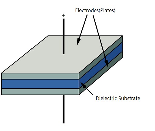
Figure 1. Structure of a Standard Capacitor
A standard capacitor uses a dielectric layer between two electrodes attached to metal plates (Fig. 1). Depending on type, the dielectric can be alumina (Al2O3), tantalum pentoxide (Ta2O5), barium titanate (BaTiO3), polypropylene, polyester, etc. Capacitance depends on dielectric permittivity, plate area, and plate separation.
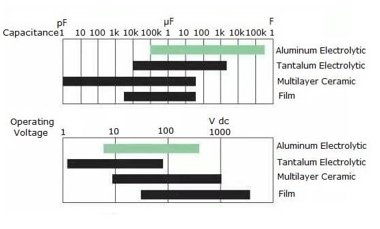
Figure 2. Capacity and Voltage Characteristics of Different Materials
In a single-layer dielectric structure, you can increase capacitance mainly by increasing area or decreasing separation. All such methods increase volume for a given voltage rating—there are practical limits on how thin the dielectric can be before breakdown.
An electric double-layer capacitor (EDLC) addresses this by using highly porous carbon electrodes (activated carbon, carbon nanotubes, graphene-like carbons) and an electrolyte (aqueous or organic). The immense surface area (often >1000–2000 m2/g) and nanometer-scale ion separation at the interface yield capacitance increases of several orders of magnitude compared with conventional capacitors of similar size. Conductive polymers and metal oxides can also be used in pseudocapacitors (see Section IV).
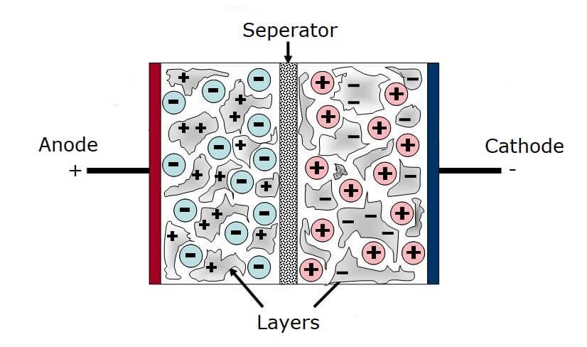
Figure 3. Structure of Supercapacitors
Voltage capability remains the key limitation of EDLC cells. Because the effective “dielectric” is a nanometer-scale ion layer that is not a true solid insulator, single-cell rated voltages are low (generally 2.3–3.0 V for organic electrolytes; aqueous cells are typically ≤1.6 V unless using advanced “water-in-salt” systems). Higher system voltages are achieved by series-connecting cells with active or passive balancing.
III Working Principle of Supercapacitors
A supercapacitor stores energy primarily through an electric double layer formed at the electrode–electrolyte interface due to Coulombic attraction (Fig. 4). In pseudocapacitors and hybrids, fast surface redox adds Faradaic charge storage.

Figure 4. Coulomb Force
Applying a potential across two porous electrodes in electrolyte draws counter-ions to each surface, forming double layers that behave like capacitors in series (one at each electrode surface).
For an ideal parallel-plate capacitor, the governing relationships are:
C = εr ε0 A / d
E = ½ C (ΔV)2
where A is plate area and d is separation. EDLCs effectively maximize A via porous carbons and minimize the effective d at the Helmholtz layer, resulting in very high capacitance with very low equivalent series resistance (ESR).
Typical activated carbon electrodes provide >1200 m2/g surface area, and the interfacial charge separation distance is on the order of nanometers, allowing specific capacitances >100 F/g (electrode basis) and low ESR suitable for high peak currents.
IV Classification of Supercapacitors
Supercapacitors have evolved in structure, materials, and performance. Broadly, they are classified by working principle and by electrolyte.
1. Classification by Principle
(1) Electric Double-Layer Capacitors (EDLCs)
EDLCs store charge at the electrode/solution interface via ion adsorption without bulk chemical transformation. When a field is applied, anions and cations migrate to opposite electrodes and form stable double layers (Fig. 5). Removing the field leaves a stored potential that can deliver current when connected to a load.

Figure 5. Operating Principle in Electric Double-Layer Capacitors
(2) Pseudocapacitors (Faradaic Quasi-capacitors)
Proposed by Conway, pseudocapacitors add fast, reversible surface redox (e.g., UPD—underpotential deposition) to double-layer storage, yielding higher specific capacitance than pure EDLCs. Electroactive materials (conductive polymers, transition-metal oxides) contribute surface-confined Faradaic charge while retaining high power capability.
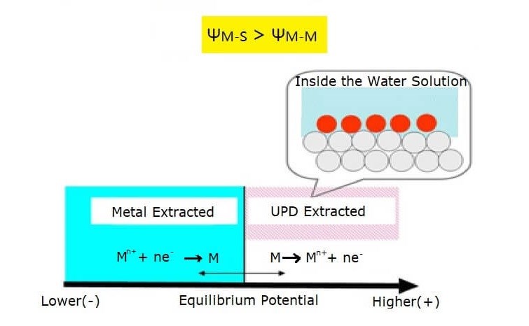
Figure 6. The Mechanism of Underpotential Deposition (UPD)
During discharge, ions return to the electrolyte through the reverse redox reaction and the stored charge is delivered to the external circuit. Hybrids such as lithium-ion capacitors (LICs) pair a capacitor-type cathode with a battery-type anode to raise energy density at some cost to power density.
2. Classified by Electrolyte
Supercapacitor electrolytes are typically aqueous (acidic, alkaline, or neutral) or organic (e.g., acetonitrile (ACN) or propylene carbonate (PC) with salts like TEABF4 or LiPF6). Aqueous systems have high ionic conductivity but lower cell voltage (water splitting), while organic systems allow higher cell voltages with lower conductivity. Recent “water-in-salt” aqueous electrolytes extend aqueous cell voltages toward ~2.2–2.5 V in specialized designs.
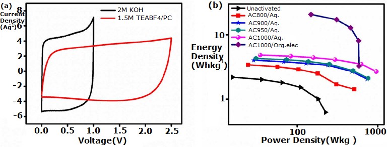
Figure 7. (a) CVs comparing aqueous vs. organic electrolytes; (b) Ragone plots illustrating energy/power trade-offs.
V Main Parameters and Performance of Supercapacitors
1. Main Parameters
(1) Service Life
Supercapacitor life is defined by capacitance and ESR drift over time/temperature/voltage. Cycle life commonly exceeds 500,000 charge–discharge cycles (and can reach into the millions) because storage is largely interfacial. Calendar life is strongly temperature- and voltage-dependent. End-of-life is usually specified at 20–30% increase in ESR and/or 20–30% loss of capacitance (not a fixed “63.2%” capacity threshold).
(2) Voltage
Each EDLC cell has a strict maximum rated voltage (often 2.3–3.0 V for organic systems). Over-voltage is destructive: electrolyte decomposition generates gas, increases ESR, causes swelling/venting, and shortens life. Operating near the recommended voltage and minimizing time at high voltage extends life. Never exceed the rated voltage of any cell; limit to ≤100% of rating unless the manufacturer specifies otherwise.
(3) Temperature
Typical operating ranges are −40 °C to +65 °C (some parts to +85 °C). Life follows an Arrhenius relationship: a common rule of thumb is every +10 °C roughly halves life (exact values are part-specific). At low temperature, ESR rises; some makers allow slightly higher operating voltage at low temperatures within datasheet limits, but this must follow manufacturer guidance.
(4) Discharge
For pulse loads, low ESR and peak current capability dominate; for small continuous loads, total capacitance and leakage current matter. Designers should evaluate voltage droop (ΔV = I·Δt / C) and ESR-related instantaneous sag (I·ESR).
(5) Charging
Common methods include constant-current (CC), constant-voltage (CV), or CC/CV blends. A series resistor or current-limited source prevents inrush and reduces stress. Reverse voltage must be avoided—EDLCs are polarized. For series strings, use passive resistive balancing or active balance ICs to prevent cell over-voltage due to parameter mismatch.
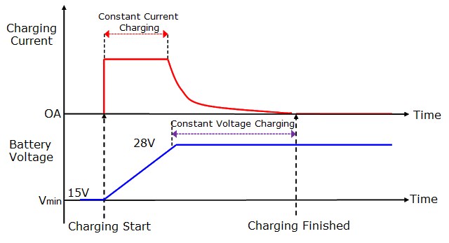
Figure 8. Constant Current & Constant Voltage Charging
2. Performance Characteristics
(1) Advantages
1) High Power Density
Very low ESR enables kW/kg power levels and rapid charge/discharge—far beyond batteries of similar size.
2) Long Cycle Life
No bulk phase change; cycle life commonly >500k with minimal degradation when used within ratings.
3) Short Charging Time
Minutes (or seconds) to reach target voltage with proper current limiting—ideal for energy buffering and peak shaving.
4) High Power with Moderate Energy
EDLC energy density is typically ~3–10 Wh/kg (modules); LICs can reach ~10–20+ Wh/kg, still far below Li-ion batteries (100–250+ Wh/kg), but with much higher power.
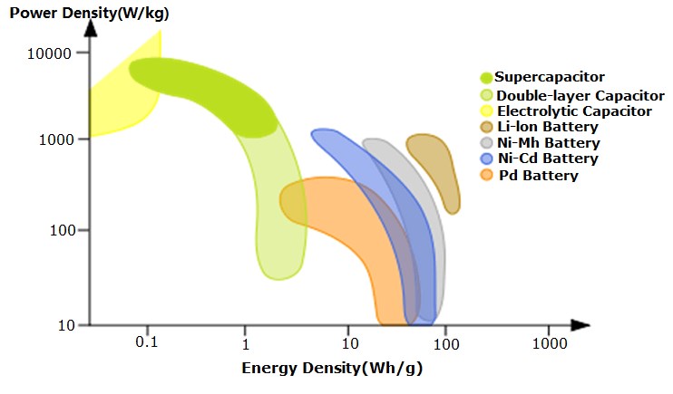
Figure 9. Power vs. Energy Density
5) Long Storage Life
With appropriate storage (cool, dry, partial voltage), calendar life can exceed 10 years. Leakage current is higher than film/electrolytic capacitors, so system design should account for it.
6) Wide Operating Temperature Range
Many parts operate from −40 °C to +65 °C (some to +85 °C) with predictable ESR change.
(2) Disadvantages
Despite strengths, supercapacitors also have limitations:
1) Leakage and Packaging Considerations
Poor mechanical placement or thermal stress can induce electrolyte venting or seal failure. Follow mounting guidelines to avoid mechanical load on terminals/can.
2) AC Usage Caveats
EDLCs are polarized and must not be reverse-biased. They are intended for DC and low-frequency applications; they are not drop-in replacements for AC line-rated capacitors. With proper DC bias and ripple limits, they can handle significant ripple current in DC systems.
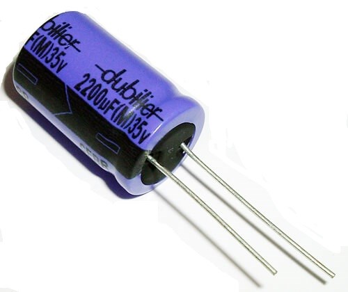
Figure 10. An Aluminum Electrolytic Capacitor
3) Cost vs. Batteries (Energy Storage)
Cost per Wh remains higher than lithium-ion batteries; however, cost per kW can be favorable due to superior power capability and cycle life. System-level hybrids often yield the best economics.
VI The Identification of Supercapacitors
1. Identification of Supercapacitors and Batteries
(1) EDLCs based on double-layer theory do not rely on bulk electrochemical reactions. They can be discharged to near 0 V without damage (observe any minimum storage voltage in the datasheet). Shorting the terminals for storage is not generally recommended; follow the manufacturer’s storage instructions.
Batteries must not be shorted and are not intended to be discharged to 0 V; doing so may cause damage or safety issues.
(2) Reverse voltage is not allowed for EDLCs; they are polarized. Batteries are also polarity-sensitive, but some chemistries include protection circuits. Always respect polarity for both devices.
(3) The voltage–charge relationship of an ideal capacitor is linear (V ∝ Q). Battery voltage typically changes nonlinearly with state of charge and depends on load profile.
Batteries and Supercapacitors
2. Identification of Electric Double-Layer Supercapacitor and Electrochemical (Pseudocapacitor/Hybrid) Supercapacitor
Electrochemical (pseudocapacitor or hybrid) devices add Faradaic contribution, so their energy density can exceed that of pure EDLCs. EDLCs typically have lower ESR and extremely high power capability. Many pseudocapacitor and LIC cells should not be discharged to 0 V—observe the chemistry-specific lower voltage limit in the datasheet.
3. Identification of Supercapacitors in Aqueous and Organic Solutions
Organic EDLCs: single-cell ratings ~2.3–3.0 V (2.7 V is common). Higher energy density than conventional aqueous EDLCs; lower ionic conductivity; flammability considerations.
Aqueous EDLCs: typical single-cell ratings ≤1.6 V; very low ESR and excellent low-temperature performance; larger physical size for the same energy. Advanced “water-in-salt” can raise cell voltage in specialized designs.
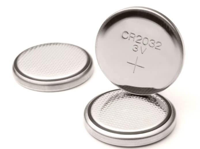
Figure 11. Button Batteries
In general, organic systems offer higher energy density; aqueous systems excel in power and safety. ESR of modern EDLCs is very low in both families, but aqueous typically has the edge on absolute ESR.
VII Precautions for Use
Not all aspects are superior to batteries for every use case. Manufacturing and application constraints require careful design. Key precautions:
1. Supercapacitors are polarized; confirm polarity before use and prevent reverse bias (use diodes or bidirectional protection where needed).
2. Do not exceed rated voltage. Over-voltage causes electrolyte decomposition, heating, gas generation, capacitance loss, and ESR rise, shortening life or causing failure.
3. Avoid high-frequency charge/discharge without proper ripple current analysis. While EDLCs handle large ripple with DC bias, they are not AC line capacitors.
4. Keep away from heat sources; manage ambient temperature to extend life (use heatsinking/airflow where appropriate).
5. For backup-power use, account for ESR-related instantaneous voltage droop at load step. Size C and ESR to meet minimum hold-up voltage (see Fig. 12).

Figure 12. A Backup Supply Circuit Diagram
6. Avoid environments with >85% RH or corrosive gases; corrosion can damage leads and can.
7. Store at −30 to +50 °C and RH <60%, partially charged if specified; follow maker guidance for long-term storage voltage.
8. On double-sided PCBs, ensure clearances so the can/case cannot short exposed conductors. Observe creepage/clearance around terminals.
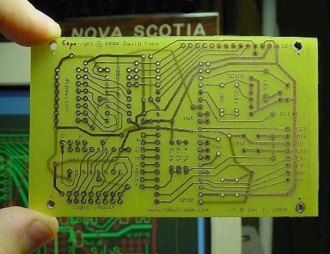
Figure 13. A Double-sided PCB Board
9. Do not let the can contact the PCB during soldering; heat can wick into the vent and degrade seals.
10. Do not tilt or twist after soldering; avoid mechanical stress on leads/terminals.
11. Avoid overheating during soldering (observe time/temperature profiles); excessive heat reduces life.
12. Clean flux residues; ionic residues can create leakage paths or corrosion.
13. Series strings require cell voltage balancing (resistive or active). Without it, cell-to-cell variation can over-voltage one or more cells, causing premature failure.
14. For any atypical application conditions, consult the manufacturer’s datasheet and application notes.
VIII Main Application Fields of Supercapacitors
1. Application in Solar Energy System
Solar PV systems—stand-alone, grid-tied, and hybrid—benefit from energy storage. Batteries provide energy capacity; supercapacitors provide high-power buffering (MPPT dynamics, inverter ride-through, and transient smoothing). EDLC banks can handle brief irradiance changes (cloud transients), reduce battery stress, and improve system reliability and lifetime.
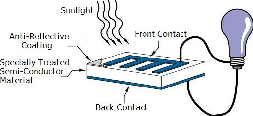
Figure 14. The Basic Operation of a PV Cell
2. Application in Wind Power System
Wind power is inherently variable; fluctuations in the 0.01–1 Hz band degrade power quality. Short-term storage using supercapacitors smooths these fluctuations, stabilizes bus voltage, supports pitch/ yaw actuators, and reduces cycling on batteries. EDLCs also provide black-start support and grid-code fault-ride-through in modern converters.
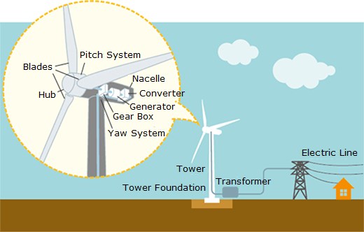
Figure 15. Traditional Wind Power Generation
3. Supercapacitors in the Development of New Energy Vehicles
In EVs/HEVs, supercapacitors complement batteries: they supply bursts of power for start/acceleration and capture regenerative-braking energy efficiently, while batteries provide sustained energy. This hybridization improves fuel economy and extends battery life. 48-V mild hybrids, start-stop systems, electric buses/trams, and fuel-cell vehicles widely employ EDLC modules and, increasingly, LICs where higher energy is needed.
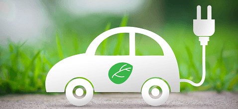
Figure 16. New Energy Vehicles
During deceleration, downhill travel, and braking, supercapacitors quickly recover energy. During launches and sudden accelerations, the EDLC provides peak power, reducing battery stress and improving overall system responsiveness and life.
Article Recommended:
1.What does a super capacitor do?
Sometimes called an ultracapacitor, a supercapacitor – like a battery – is a means to store and release electricity. But rather than storing energy in the form of chemicals, supercapacitors store electricity in a static state, making them better at rapidly charging and discharging energy.
2.Will super capacitors replace batteries?
Operators use the supercapacitors to capture energy generated when a bus brakes for one of its many stops, and then discharge the power to help the bus get started from its dead stop. For that purpose, supercapacitors can replace batteries entirely on hybrid buses, while all-electric buses require fewer batteries.
3.How long will a super capacitor hold its charge?
The Supercaps have a charging time from 1 to 10 seconds, compared to 10 to 60 minutes for a full charge on a battery. Supercapacitors can reach up to one million cycles, while typical batteries can have 500-1000 charge-discharge cycles.
4.How much do super capacitors cost?
The cost of the supercapacitors after 40 years is $2,400 to $6,000 per kWh if they last that long, and the batteries are actually $2,000 to $4,000 after 40 years if they last an average of 10 years, because they would have to be replaced at least 4 times for every one time that the supercapacitors are replaced.
5.Which is better battery or capacitor?
A capacitor is able to discharge and charge faster than a battery because of this energy storage method also. ... However, in general batteries provide higher energy density for storage, while capacitors have more rapid charge and discharge capabilities (greater Power density).
 What is Feedthrough Capacitor?UTMEL06 November 202139236
Hello, everyone. I am Rose. Today I will introduce the feedthrough capacitor to you. The feedthrough capacitor is a three-terminal capacitor that is used to reduce high frequencies. The feedthrough capacitor, unlike regular three-terminal capacitors, is directly installed on the metal panel, resulting in a lower grounding inductance and a negligible effect on the lead inductance.
Read More Detailed Explanation About Twenty Kinds of CapacitorUTMEL08 November 20218245
Hello everyone, I am Rose. Today I will introduce 20 kinds of capacitor to you. I will illustrate them in three or four aspects: Structure, features, Usages, advantages and disadvantages.
Read More What is a Polypropylene Capacitor?UTMEL08 November 202120018
A polypropylene capacitor is a kind of capacitor with a very stable electric capacity. It is often used in applications requiring very precise capacitance and can replace most polyphenylene or mica capacitors.
Read More What is the Difference between MOM, MIM and MOS Capacitors?UTMEL17 April 202564289
This article mainly introduces the structure, principle, advantages and disadvantages of MOM, MIM and MOS capacitors and the difference between them.
Read More What is a Power Capacitor?UTMEL20 November 20215760
Power capacitors are capacitors used in power systems and electrical equipment. Any two pieces of metal conductors are separated by an insulating medium to form a capacitor. The size of the capacitor is determined by its size and the characteristics of the insulating medium between the two plates.
Read More
Subscribe to Utmel !


