What is a Safety Capacitor?

How to use Safety Capacitors - What are they?
In electrical and electronic systems, safety capacitors play a critical role in ensuring operational reliability while protecting users from potential hazards. Unlike standard capacitors, safety capacitors are specifically designed to maintain integrity during failure modes, preventing electric shock hazards and ensuring personal safety (Murata Manufacturing, 2021). These specialized components comply with rigorous safety regulations and undergo extensive testing to verify their protective characteristics under abnormal operating conditions.

Safety capacitors represent a crucial component in modern electronic design, particularly in applications where equipment connects directly to main power sources. Their implementation addresses both electromagnetic compatibility (EMC) requirements and fundamental safety concerns, making them indispensable in consumer electronics, industrial equipment, and medical devices (Sarjeant & MacDougall, 2020).
Catalog
I What is a Safety Capacitor?
Why do we need a safety capacitor? Because after the safety capacitor fails, it will not cause electric shock and does not endanger personal safety.
Safety capacitors are specialized capacitive components engineered to meet stringent safety standards and pass comprehensive certification testing. These components are designed with failure mode considerations as a primary design parameter—ensuring that when failure occurs, it happens in a predetermined safe manner that protects users from electric shock and prevents equipment damage (IEC, 2020).
Within industrial applications, safety capacitors must conform to international safety regulations such as IEC 60384-14, UL 60384-14, or EN 60384-14, which establish specific performance requirements and test methodologies. These standards ensure that capacitors maintain their protective characteristics even under extreme conditions including overvoltage events, temperature fluctuations, and moisture exposure (Wang & Jones, 2022).
Safety regulations provide explicit guidance regarding electronic components to prevent hazards including electric shock, energy-related incidents (fire/arc/explosion), radiation exposure, mechanical failures, thermal dangers, and chemical risks. These standards require manufacturers to supply end-users with products featuring robust safety mechanisms that protect lives and property during both normal operation and fault conditions (Underwriters Laboratories, 2021).
II Safety Capacitor Function
(1) Filtering
Safety capacitors effectively suppress electromagnetic interference (EMI) by filtering unwanted signal components from power lines. This filtering function is crucial for ensuring that equipment meets electromagnetic compatibility requirements while maintaining proper operation in noisy electrical environments (Williams, 2021).
(2) Safer and more reliable
Based on the two functions, for safety and EMC considerations, safety capacitors are generally used for power supply inlets.
At the input end of the AC power supply, three safety capacitors are added to suppress EMI conduction interference. They are used in power filters to filter common mode and differential mode interference.
For example: when capacitors are used to eliminate noise in power cross-line circuits, normal voltages and abnormal pulse voltages (such as lightning) must be considered, which may cause smoke or fire. Therefore, cross-line capacitors must use safety capacitors.
The safety capacitor has a large margin for the breakdown voltage. If the nominal voltage of the safety capacitor is only 400V or lower, its withstand voltage is at least 1000V, so it is difficult to break down.
Even if the capacitor is broken down, because it’s filled with flame-resistant materials, which will explode, only causing a short circuit not a fire.
The capacitor safety discharge is different from ordinary capacitor discharges. The charge of ordinary capacitors will remain for a long time after the external power supply is disconnected.
You'll get a shock if you touch it. But safety capacitors do not have this problem.
III Safety Capacitor Classification
Position of AC safety capacitor in the circuit:
(1) Across-the-ine
(2) Antenna-coupling
(3) Line-bypass
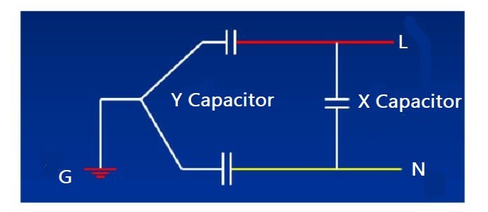
The safety capacitor in part (1) is called X capacitor due to wiring
The safety capacitor in part (3) is called Y capacitor because the circuit is like "Y".
X capacitor refers to the capacitor across L-N
Y capacitor refers to the capacitor across L-GN-G
(Note: L=LINE NENEUTRAL G=GROUND)

Figure 1. Capacitor Terminal L N G
That is: the X capacitor is between the live wire and the neutral wire. The Y capacitor is between the live wire or the neutral wire and the ground wire.
Note: In general safety test, the components must pass the test standards of X capacitor and Y capacitor at the same time.
For example, X1/Y2 means the component meets the test standards of X capacitor and Y capacitor at the same time.
1. X Capacitor
According to the safety level, X capacitor can be divided into 3 types:
Subclass | Allowable Peak Pulse Voltage (kV) | Overvoltage Class IEC664 | Application | Peak Pulse Voltage Vp applied before Endurance Test (kV) |
X1 | 2.5kV<Up≤4kV | Ⅲ | High Pulse Application | CR≤1.0uF, 4kV CR>1.0uF, 4kV/ |
X2 | Up≤2.5kV | Ⅱ | General Purpose | CR≤1.0uF, 2.5kV CR>1.0uF, 2.5kV/ |
X3 | Up≤1.2kV | -- | General Purpose | -- |
X capacitors are further subdivided into specific categories based on their voltage withstand capabilities:
X1: Designed for high pulse applications, these capacitors withstand peak voltages up to 4.0kV. They are suitable for installation in locations where significant overvoltage transients are expected.
X2: Engineered for general-purpose applications, X2 capacitors handle peak voltages up to 2.5kV. These represent the most common X-type capacitors in consumer electronics.
X3: Specified for applications with lower transient expectations, these capacitors withstand peak voltages up to 1.2kV (Würth Elektronik, 2021).
X capacitor is generally marked with safety certification marks and withstand voltage AC250V or AC275V. But from the table above, the actual DC withstand voltage is at least 2500V (X2) or more. Therefore, do not casually use ordinary capacitors with nominal withstand voltage as AC250V or DC400V for replacement.
Generally, X capacitors are mostly polyester film capacitors with large ripple currents. This type of capacitor has a large volume, but it allows a large current for instantaneous charging and discharging, with small internal resistance.
Ordinary capacitors have low ripple current and high dynamic internal resistance. So if we use ordinary capacitors instead of X capacitors, the ripple current index is also difficult to meet the requirements.
According to actual needs, the capacitance of X capacitor is allowed to be larger than that of Y capacitor. Due to the slow discharge process of the capacitor, the power plug may be charged for a long time after disconnected. So, a safety resistor must be connected in parallel at both ends of the X capacitor.
The safety standard states that when the power cord of the working machine is unplugged, within two seconds, the voltage (or ground potential) at both ends of the power plug must be less than 30% of the original rated working voltage.
2. Y Capacitor
According to the safety level, Y capacitors are divided into 4 categories:
Subclass | Type pf Insulation Bridge | Rated Voltage(VAC) | Test Voltages for Quality Approval, Periodic and Lot-by-Lot Testing | Peak Pulse Voltage Vp applied before Endurance Test |
Y1 | Double Insulation or Reinforced Insulation | ≤250 | 4000VAC | 8.0kV |
Y2 | Basic Insulation or Supplementary Insulation | ≥150V ≤250V | 1500VAC | 5.0kV |
Y3 | Basic Insulation or Supplementary Insulation | ≥150V ≤250V | 1500VAC | none |
Y4 | Basic Insulation or Supplementary Insulation | <150V | 900VAC | 2.5kV |
Y capacitors are classified into specific subtypes based on their voltage withstand capabilities and isolation characteristics:
Y1: These capacitors feature reinforced insulation and can withstand peak voltages up to 8.0kV. Y1 capacitors are used in applications where safety isolation is critical, such as medical equipment.
Y2: With basic insulation properties, Y2 capacitors withstand peak voltages up to 5.0kV. These represent the most commonly used Y-type capacitors in standard electronic equipment.
Y3: Offering reduced isolation capabilities, Y3 capacitors handle peak voltages up to 2.5kV. They are used only when protected by additional safety measures.
Y4: These capacitors withstand peak voltages up to 1.5kV and are suitable only for isolated secondary circuits with appropriate supplementary protection (EPCOS, 2021).
Y capacitors are mostly orange or blue and are generally marked with safety certification (such as UL, CSA, etc.) and withstand voltage AC250V or AC275V. However, from the above table, its actual DC withstand voltage is 5000V (Y2) or more.
Y capacitors should not be replaced by ordinary capacitors with AC250V or DC400V nominal withstand voltage.
The capacitance of the Y capacitor must be limited, to control the leak current flowing through it under the rated frequency and rated voltage, thereby influencing the EMC performance of the system.
GJB151 states that the capacitance of the Y capacitor should not be greater than 0.1uF. Normally, for the machine working in the subtropical zone, the ground leak current should not exceed 0.7mA. And for machines working in the temperate region, the ground leak current must not exceed 0.35mA. Therefore, the total capacitance of Y capacitor cannot exceed 4700PF (472).
In addition to meeting the corresponding grid withstand voltage, the Y capacitor should also have sufficient safety margin in electrical and mechanical properties, to avoid breakdown and short-circuit phenomenon under extremely harsh environments. This voltage withstands performance is significant to protect personal safety.
3. Difference between X Capacitor and Y Capacitor
The fundamental distinction between X and Y capacitors lies in their failure consequences:
X capacitors connect between line and neutral conductors where failure presents minimal shock hazard to users. Their failure mode primarily impacts equipment functionality rather than user safety.
Y capacitors connect between line or neutral and ground, where failure could potentially expose users to dangerous leakage currents. Consequently, Y capacitors must meet more stringent safety requirements with emphasis on maintaining isolation barriers (Illinois Capacitor, 2021).
Additionally, Y capacitors typically feature significantly smaller capacitance values (often in the picofarad to nanofarad range) compared to X capacitors (typically in the nanofarad to microfarad range). This limitation stems from the need to restrict leakage current to safe levels in Y-type applications (Murata Manufacturing, 2022).
(1) X capacitors suppress differential mode interference, Y capacitors suppress common-mode interference.
(2) Based on the limitation of leak current, the capacitance of the Y capacitor cannot be too large. Generally, the capacitance of the X capacitor is in uF and the Y capacitance is nF.
X capacitors often use metalized polypropylene film capacitors (MPX) resistant to high ripple current. This type of capacitor has a large volume, but it allows a large current for instantaneous charging and discharging, with small internal resistance.
The X capacitor has plastic packages, a square structure, and internal high-voltage OPP material (made by winding metalized polypropylene material). OPP material has a better electrical performance. Also, when the X capacitor made of it in parallel with the input end, the high-frequency pulse interference can be reduced.
Y capacitors often use high-voltage ceramics.
Precautions for Use
1. X and Y capacitors must meet the working voltage requirements. For those that exceed the nominal voltage, you can choose to use them in series to share the voltage, but these capacitors should be exactly the same.
2. X and Y capacitors must meet temperature requirements. For Y capacitors, the maximum temperature in UL certification can only be 85 degrees. However, the temperature for European certification is often higher. Currently, UL agrees to use the European certified Y capacitor temperature as the maximum operating temperature
3. Consider the magnitude of the pulse voltage at the circuit input. Different capacitors have different pulse voltages. Usually, the withstand voltage of the capacitor cannot be less than the peak pulse voltage in the circuit.
For example, for the input terminal of UPS, the peak value of the pulse voltage is 4000V, so the input terminal can only choose X1 safety capacitors, Y1 safety capacitors, and Y2 safety capacitors.
IV How to Select Safety Capacitors
Safety capacitors are familiar to us, and we often see them in switching power supplies. But many beginners don't know how to choose one for use. The following tells you about the type selection.
First, you can find a formal safety capacitor manufacturer, and it'll provide you with a selection book.
If you don’t know how to choose, you can talk with the technical staff, and he/she will give the recommended safety capacitor model. Or you can apply for a sample test to find a suitable safety capacitor.
1. Selection of Safety Capacitor Parameters
Safety capacitors are generally used in power circuits for bypass, decoupling, filtering, and energy storage. It is very important to select the parameters of safety capacitors. If the selected capacitor does not meet the actual requirements, it is likely to cause serious problems.
(1) Rated Capacitance (CR)
First, we should consider the rated capacitance (CR), the capacitance value marked on the capacitor. The capacitance of mica and ceramic capacitors is low (generally below 5000pF); the capacitance of paper and plastic capacitors is between 10μF to 5000μF; usually, electrolytic capacitors have a larger capacitance.

Figure 2. 5000PF Ceramic Capacitor
(2) Rated Voltage
The rated voltage is another important parameter. It's the maximum DC voltage or AC voltage effective value, or the peak pulse voltage that can be continuously applied to the capacitor, at any temperature between the lower category temperature and the rated temperature.
When capacitors are used in high voltage applications, we must pay attention to the effects of the corona. Corona is caused by the gaps between the dielectric/electrode layers. In addition to generating parasitic signals that can damage the device, it can also cause a dielectric breakdown of the capacitor.
Corona often occurs under AC or pulse voltage. We should ensure the sum of DC voltage and AC peak voltage does not exceed the DC rated voltage during use.
(3) Temperature Range
In addition, it is necessary to consider the temperature range. It refers to the ambient temperature range for continuous operation determined by the capacitor design. It depends on the temperature limit value of its corresponding categories, such as the upper category temperature, the lower category temperature, and the rated temperature.
2. Key Points
One typical failure mechanism of safety capacitors is low voltage failure. Normally, everyone likes to leave a large margin for voltage resistance, thinking that even if there are some defects in the design, the device will not fail. Is it true? First, let’s see the typical phenomenon of low voltage failure:
(1) The actual using voltage is much lower than the rated withstand voltage of the capacitor, generally below 10% of the rated value;
(2) The capacitor will fail after the humidity test or damp pretreatment;
(3) After humidity test and damp pretreatment, if we perform high-temperature test or circuit board baking, the capacitance will return to normal;

Figure 3. Circuit Board Baking
(4) If we remove the failed capacitor from the circuit board, add a high voltage at both ends, about 60%-75% of the rated value, the capacitor performance will return to normal.
If the safety capacitor you use has a similar phenomenon, it might have a low voltage failure. So what's the reason?
There is a dielectric between the two pole pieces of a safety capacitor. The capacitor pole pieces and dielectric are packed by the shell. In fact, the shell will not be 100% sealed, which makes it possible for moisture to penetrate.
For example, moisture has penetrated into a safety capacitor with a 50V withstand voltage. When a 5V voltage is applied across the capacitor, the moisture attached to the dielectric becomes a leak current channel. But because of the low voltage, the leak current is not very large, so as the heat generated on the impedance. They can not heat and evaporate the water vapor but can destroy the energy storage characteristics of the capacitor. As a result, the capacitor fails.
In the high-temperature experiment, the water vapor evaporates, the leak current channel no longer exists, and the capacitance returns to normal. If a high voltage is applied, the on-resistance remains unchanged. As the voltage increases, the leak current is bound to increase, producing a larger energy I2R on the impedance. And this heat will also evaporate the moisture. As a result, the capacitor leak current will gradually decrease until the energy storage function is restored.
Therefore, we should not leave too much margin for the voltage resistance of safety capacitors, which is a key point in the selection.
V Principle of Safety Capacitor Step-down
The working principle of the safety capacitor step-down is not complicated. It is to use the capacitive reactance generated by the capacitor at a certain AC signal frequency, to limit the maximum operating current. For example, under 50Hz power frequency, the capacitive reactance generated by a 1uF capacitor is about 3180 ohms.
When a 220V AC voltage is applied to both ends of the capacitor, the maximum current flowing through the capacitor is about 70mA. However, there is no power consumption on the capacitor. If the capacitor is an ideal capacitor, the current flowing through is a reactive current, and the work it does is reactive power.
According to this feature, if we connect a resistive element in series with a 1uF capacitor, the voltage obtained at both ends and the power consumption generated completely depend on the characteristics of the resistive element.
For example, we connect a 110V/8W light bulb with a 1uF capacitor in series. When it is connected to a 220V/50Hz AC voltage, the light bulb is lit and emits normal brightness without being burnt. Because the current required is 8W/110V=72mA, which is consistent with the current limiting characteristics of the 1uF capacitor.
In the same way, we can also connect a 5W/65V bulb and a 1uF capacitor in series to a 220V/50Hz AC. The bulb will also be lit without being burned because the working current of a 5W/65V bulb is about 70mA.
Therefore, the safety capacitor step-down is actually the use of capacitive reactance to limit current. The capacitor actually plays a role in limiting the current, and dynamically distributing the voltage across the capacitor and the load.
Pay attention to the following points when using step-down:
(1) Choose an appropriate capacitor according to the current magnitude of the load and the working frequency of the alternating current, rather than the voltage and power of the load.
(2) Current-limiting capacitors must be non-polar capacitors, and electrolytic capacitors must not be used. And the capacitor withstand voltage must be above 400V. The most ideal capacitor is an oil-filled iron-case capacitor.
(3) Safety capacitors can not be used for high power.
(4) The safety capacitor step-down is not suitable for dynamic load.
(5) When DC is required, half-wave rectification should be used to meet the constant load. Bridge rectification is not recommended.
Conclusion
Safety capacitors represent a specialized component category that addresses both electromagnetic compatibility requirements and fundamental safety concerns in electronic equipment. Their dual role in filtering unwanted signals while ensuring user protection makes them indispensable elements in modern electronic design.
By understanding the classifications, selection criteria, and application principles of safety capacitors, designers can implement these components effectively to achieve reliable performance while maintaining compliance with international safety regulations. As electronic systems continue to evolve, safety capacitors remain essential elements in the protection strategy for both equipment and users.
References
AVX Corporation. (2022). Safety and EMI suppression capacitors: Application guidelines (Technical Note). https://www.avx.com/docs/techinfo/safetyemi.pdf
EPCOS. (2021). Film capacitors for EMI suppression and safety applications (Product Manual). TDK Electronics AG.
IEC. (2020). IEC 60384-14:2020: Fixed capacitors for use in electronic equipment - Part 14: Sectional specification - Fixed capacitors for electromagnetic interference suppression and connection to the supply mains. International Electrotechnical Commission.
Illinois Capacitor. (2021). Safety certified capacitors: Application guide (Technical Bulletin). https://www.illinoiscapacitor.com/pdf/papers/safety_certified_capacitors.pdf
KEMET Electronics. (2021). Safety capacitors selection guide (Application Note). https://www.kemet.com/en/us/applications/safety-capacitor-selection.html
KEMET Electronics. (2022). Safety and EMI suppression film capacitors (Technical Specification). https://content.kemet.com/datasheets/KEM_F3101_F862.pdf
Montrose, M. I. (2021). EMC and the printed circuit board: Design, theory, and layout made simple (3rd ed.). IEEE Press. https://doi.org/10.1109/9780470544341
Recommended Article:
What is a Decoupling Capacitor?
1.How do I test a safety capacitor?
When measuring, you can use a multimeter R × 10k block. Use two test leads to connect the two pins of the capacitor. The resistance should be infinite. If the measured resistance value (the pointer swings to the right) is zero, it means that the capacitor leakage is the damaged or internal breakdown.
2.Why are capacitors dangerous?
Capacitors hold electric charge even after disconnecting them from the power source; for seconds to minutes to days. Capacitors do not consume power but just draws energy from source and stores it. When discharged, they throw out whatever stored almost instantly which is why it tends to be dangerous.
3.When should a safety capacitor be used?
The function of these capacitors is to protect against surges and transients, as well as providing EMI filtering. Safety capacitors are circuit-specific and serve to protect the circuit and the user from high-voltage surges by shunting the impulse energy to ground. One common cause of such surges is lightning strikes.
4.What happens if a capacitor fails?
During a failure, half of the capacitor could fail open, which would result in overall capacitance being lost. Or half of the capacitor could fail short, which would result in the overall capacitance being halved.
5.How long can a capacitor last?
Capacitors have a limited life span. Most are designed to last approximately 20 years, but a number of factors can cause them to wear out quicker.
 What is Feedthrough Capacitor?UTMEL06 November 202138701
Hello, everyone. I am Rose. Today I will introduce the feedthrough capacitor to you. The feedthrough capacitor is a three-terminal capacitor that is used to reduce high frequencies. The feedthrough capacitor, unlike regular three-terminal capacitors, is directly installed on the metal panel, resulting in a lower grounding inductance and a negligible effect on the lead inductance.
Read More Detailed Explanation About Twenty Kinds of CapacitorUTMEL08 November 20218078
Hello everyone, I am Rose. Today I will introduce 20 kinds of capacitor to you. I will illustrate them in three or four aspects: Structure, features, Usages, advantages and disadvantages.
Read More What is a Polypropylene Capacitor?UTMEL08 November 202119677
A polypropylene capacitor is a kind of capacitor with a very stable electric capacity. It is often used in applications requiring very precise capacitance and can replace most polyphenylene or mica capacitors.
Read More What is the Difference between MOM, MIM and MOS Capacitors?UTMEL17 April 202563118
This article mainly introduces the structure, principle, advantages and disadvantages of MOM, MIM and MOS capacitors and the difference between them.
Read More What is a Power Capacitor?UTMEL20 November 20215666
Power capacitors are capacitors used in power systems and electrical equipment. Any two pieces of metal conductors are separated by an insulating medium to form a capacitor. The size of the capacitor is determined by its size and the characteristics of the insulating medium between the two plates.
Read More
Subscribe to Utmel !
![11028]() 11028
11028HEYCO PRODUCTS
![EMBAT945GSERRDK]() EMBAT945GSERRDK
EMBAT945GSERRDKIntel
![BEAGLEXM]() BEAGLEXM
BEAGLEXMTexas Instruments
![UBA2017DB1064598]()
![WSA1YR1000N]() WSA1YR1000N
WSA1YR1000NSchneider
![XR15715EVB]() XR15715EVB
XR15715EVBExar Corporation
![HQPACK100RB179]() HQPACK100RB179
HQPACK100RB179Infineon
![MAX17633AEVKITA#]() MAX17633AEVKITA#
MAX17633AEVKITA#Analog Devices
![DC2365A-E]() DC2365A-E
DC2365A-EAnalog Devices
![DC682A]() DC682A
DC682AAnalog Devices


