
 Product
 Brand
Brand Articles
 Tools
Tools
What are Varactor Diodes?

Varactor Diode Explained
Catalog
Ⅰ Introduction
The varactor diode (also known as a varicap diode, tuning diode, or variable capacitance diode) is a specialized semiconductor device designed to act as a voltage-controlled capacitor. The capacitance of a varactor diode is generally small, with maximum values typically ranging from a few picofarads (pF) to hundreds of picofarads.
A key characteristic is the capacitance ratio—the ratio of maximum capacitance (at low reverse voltage) to minimum capacitance (at high reverse voltage). While standard abrupt junction varactors offer a ratio of about 5:1, modern hyperabrupt junction varactors can achieve ratios of 10:1 or higher, allowing for wider tuning ranges.
These components are indispensable in high-frequency circuits for automatic tuning, frequency modulation (FM), and phase-locked loops (PLLs). They function as variable capacitors in the tuning loops of television receivers, FM radios, and mobile communication devices. The use of varactor diodes has replaced bulky mechanical variable capacitors, enabling smaller, more reliable, and automated electronic tuning systems.
Ⅱ Features of varactor diodes

Varactor diode
The operational conditions of a varactor diode have similarities to a Zener diode, but their functions differ fundamentally. Both operate in the reverse voltage bias region. However, while a Zener diode is designed to operate in the breakdown region to regulate voltage, a varactor diode must operate before the breakdown voltage to function as a capacitor.
When a reverse voltage is applied across the varactor diode, the depletion region (PN junction) widens. Because the depletion region is essentially devoid of charge carriers, it acts as an insulator (dielectric) between the conductive P-type and N-type regions (plates). This structure forms a parallel plate capacitor.
The physics follows the capacitor formula:
C = εA / d
Where:
C is capacitance
ε is the permittivity of the semiconductor material
A is the area of the junction
d is the width of the depletion region
As reverse voltage increases, the depletion width (d) increases, causing the capacitance (C) to decrease. Conversely, lowering the voltage narrows the depletion region, increasing capacitance. Unlike standard diodes where junction capacitance is a parasitic effect to be minimized, varactor diodes are manufactured with specific doping profiles to maximize this capacitance change.
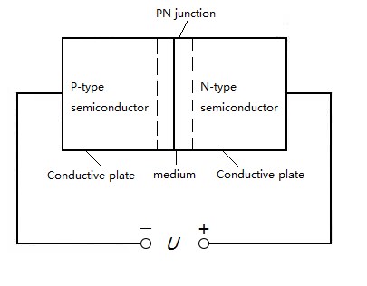
The formation of varactor junction capacitance
Electronic tuners built with varactor diodes offer significant advantages over mechanical tuning: they have no moving parts, are immune to dust and moisture, withstand vibration, and allow for remote control and digital PLL synthesis. This makes them the standard for modern RF applications, including Voltage Controlled Oscillators (VCOs) in wireless equipment.
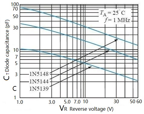
Varactors and reverse bias
Relationship Summary:
(a) Reverse bias voltage increases → Depletion layer widens → Capacitance decreases.
(b) Reverse bias voltage decreases → Depletion layer narrows → Capacitance increases.
Ⅲ Varactor diodes symbol
The standard circuit symbol for a varactor diode combines the traditional diode symbol with the parallel lines of a capacitor. This visualizes its dual nature: a diode structure functioning as a capacitor.

Varactor diodes symbol
Connection Note: The "+" and "-" signs often seen in diagrams indicate the polarity of the diode itself (Anode and Cathode). However, for the varactor to function, it must be reverse-biased. In a circuit:
The Cathode (the bar side/negative pole of the symbol) connects to the positive DC potential.
The Anode (the triangle side/positive pole) connects to the lower potential or ground.
Common text designations are "VD", "V", or "VC" followed by a number (e.g., VD1).
Ⅳ The main parameters of varactor diodes
Selecting the correct varactor requires understanding its key parameters. Beyond standard diode metrics, the following are critical for RF design:
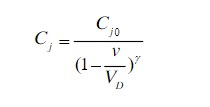
Junction Capacitance ($C_T$ or $C_J$): The capacitance value at a specific reverse voltage (e.g., $C_{3V} = 15pF$). Datasheets usually provide values at low voltage (near 0-4V) and high voltage.
Capacitance Ratio ($C_{ratio}$): A measure of the tuning range. It is the ratio of capacitance at a low voltage to capacitance at a high voltage (e.g., $C_{2V} / C_{20V}$). A higher ratio allows for a wider frequency tuning range.
Maximum Reverse Working Voltage ($V_{RM}$): The maximum DC voltage that can be applied without causing the diode to break down. Exceeding this leads to component failure. Common values range from 20V to 60V depending on the specific part.
Quality Factor (Q Value): This represents the efficiency of the capacitor. Ideally, a capacitor has infinite resistance, but a real varactor has a small series resistance ($R_S$). The Q value is the ratio of reactance to resistance ($Q = X_C / R_S$). A higher Q means lower energy loss, which is vital for maintaining sharp selectivity in tuning circuits.
Series Resistance ($R_S$): The internal resistance of the semiconductor material. Lower $R_S$ is better, as it directly improves the Q value.
Cutoff Frequency ($f_c$): The frequency at which the Q factor drops to unity (1). This determines the upper frequency limit at which the diode is useful. $f_c = 1 / (2 \pi R_S C_J)$.
Ⅴ Working principle of varactor diodes
Varactor diodes (or voltage-controlled varactors) utilize the inherent properties of the P-N junction depletion region.
When a P-N junction is formed, a natural depletion region exists where electrons and holes recombine.
Forward Bias: If current flows forward, this region collapses, and the device conducts.
Reverse Bias: When positive voltage is applied to the N-type material and negative to the P-type, charge carriers are pulled away from the junction. This widens the depletion zone. Since this zone lacks carriers, it acts as a dielectric insulator. The P and N regions on either side act as conductive plates.
The ability to control the width of this "dielectric" by adjusting the DC voltage allows the device to function as a variable capacitor. This variable capacitance ($C$) is then used in LC resonance circuits to change the resonant frequency ($f$) according to the formula:
$f = \frac{1}{2\pi\sqrt{LC}}$

(a) Full Equivalent Circuit; (b) Simplified Equivalent Circuit
In the equivalent circuit:
$C_J$: Junction capacitance (the variable part).
$R_S$: Series resistance (bulk resistance of the silicon).
$L_S$: Lead inductance (parasitic inductance from packaging).
$C_C$: Case capacitance.
For most practical applications (Figure b), we simplify this to a variable capacitor in series with a resistor.
Packaging: Varactors come in various packages. Glass and plastic packages are common for general consumer electronics (radio, TV). Surface mount (SMD) packages (like SOT-23 or SOD-323) are now the standard for mobile phones and modern electronics.
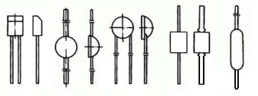
Varactor diode package forms
Ⅵ Application of varactor diodes
Varactors are constructed using Silicon (Si) or Gallium Arsenide (GaAs). GaAs devices generally offer higher Q values and are used in higher frequency applications (microwaves). The manufacturing process has evolved from older alloy-diffusion methods to modern planar epitaxial or mesa structures, which provide better consistency and hyperabrupt characteristics for larger tuning ranges.
Primary Applications:
VCO (Voltage Controlled Oscillators): The core of frequency synthesizers in phones, Wi-Fi routers, and GPS.
Active Filters: Tunable bandpass filters that select specific frequencies.
Frequency Modulation: Creating FM signals by modulating the carrier frequency with audio data.
Harmonic Generation: Used in frequency multipliers.
Typical Application Circuit 1: Parallel Resonant Tank

In this circuit:
Capacitor $C_1$ is in series with the varactor $VD_1$. This combination is in parallel with Inductor $L_1$. This forms an LC tank circuit.
The control voltage ($V_{Control}$) acts as a reverse DC bias on $VD_1$. $C_1$ blocks this DC voltage from shorting to ground through the inductor while allowing the AC RF signal to pass.
When the DC voltage changes, $VD_1$'s capacitance changes, altering the total capacitance of the loop and shifting the resonant frequency.
Typical Application Circuit 2: Tuned Oscillator

This figure illustrates a classic voltage-tuned oscillator circuit.
The inductor $L_2$ couples the RF signal. The primary tank circuit consists of $L_1$, and the series combination of $C_1$ and the varactor $CR_1$.
$V_{in}$ is the tuning voltage. Capacitor $C_2$ acts as a bypass/filter capacitor to ensure the tuning voltage is clean (noise on the tuning line causes frequency jitter or phase noise).
Because resonant frequency $f$ is proportional to $1/\sqrt{C}$, and $C$ is non-linearly related to voltage, the resulting frequency-to-voltage curve is parabolic. In modern digital systems (like PLLs), this non-linearity is compensated for by the loop filter and software control.
Article Recommended:
Switching Diodes Basics: Working, Types and Circuit Analysis
 UTMEL
UTMEL
We are the professional distributor of electronic components, providing a large variety of products to save you a lot of time, effort, and cost with our efficient self-customized service. careful order preparation fast delivery service
What is varactor diode and its application?
Varactor or varicap diodes are used mainly in radio frequency or RF circuits to provide voltage controlled variable capacitance. These electronic componenta can be used in a whole variety of ways where a capacitance level needs to be controlled by a voltage.
How does a varactor diode work?
The Varactor diode is made up of n-type and p-type semiconductor material. ... The varactor diode operates only in reverse bias. Because of reverse bias, the current does not flow. If the diode is connected in forward biasing the current starts flowing through the diode and their depletion region become decreases.
Is varactor a diode?
Varactor Diode Varactor diode is a type of diode whose internal capacitance varies with respect to the reverse voltage. It always works in reverse bias condition and is a voltage-dependent semiconductor device.
What is the key feature of varactor diode?
Important characteristics are capacitance when designated bias voltage is applied (ex. C3V where VR=3V), capacitance variation when applied voltage changes (capacitance ratio) and series resistance that affects Q index when used in oscillators or filters.
 All You Need to Know About Rectifier CircuitUTMEL24 April 202517648
All You Need to Know About Rectifier Circuit
Read More 15 Key Elements of Diode SelectionUTMEL26 November 202118921
Hello everyone, I am Rose. Welcome back to the new post today. Diodes are one of the most common components in our circuit boards. So, what factors should be considered when selecting models?
Read More What is a PIN Diode?UTMEL04 February 202110245
While diodes with a simple PN junction are by far the most common type of diode in operation, in a variety of applications, other forms of diode may be used. The PIN diode is one type that is used for a number of circuits. In a variety of places, this diode type is used. For RF switching, the PIN diode is very fine, and the PIN structure in photodiodes is very useful as well.
Read More Microwave Diode: Introduction and TypesUTMEL07 January 202126064
Microwave diodes are diodes that work in the microwave frequency band. It is a solid-state microwave device. Microwave band usually refers to the frequency from 300 MHz to 3000 GHz. After the discovery of the point contact diode effect at the end of the 19th century, microwave diodes such as PIN diodes, varactor diodes, and Schottky diode tubes appeared one after another. Microwave diodes have the advantages of small size and high reliability, and are used in microwave oscillation, amplification, frequency conversion, switching, phase shifting and modulation.
Read More What Determines the Maximum Operating Frequency of a Diode?UTMEL29 June 202212945
Hello, wish you a wonderful day. In this essay, we first pose the following query: what determines the diode's maximum operating frequency? In regards to the solution, the first thing we need to understand is that the junction capacitance and the reverse recovery time of the diode are two distinct concepts. The charging and discharging times of the junction capacitance cannot match the reverse recovery time. You say that, why? Let's start by taking a look at these facts.
Read More
Subscribe to Utmel !
![BLM41PG102SH1L]() BLM41PG102SH1L
BLM41PG102SH1LMurata Electronics
![FBMH1608HM102-T]() FBMH1608HM102-T
FBMH1608HM102-TTaiyo Yuden
![BLM18BA121SN1D]() BLM18BA121SN1D
BLM18BA121SN1DMurata Electronics
![742792034]() 742792034
742792034Würth Elektronik
![FBMH1608HM101-T]() FBMH1608HM101-T
FBMH1608HM101-TTaiyo Yuden
![MH2029-221Y]() MH2029-221Y
MH2029-221YBourns Inc.
![ACF321825-102-TD01]() ACF321825-102-TD01
ACF321825-102-TD01TDK Corporation
![NFM18PC225B0J3D]() NFM18PC225B0J3D
NFM18PC225B0J3DMurata Electronics
![BK1005LM182-T]() BK1005LM182-T
BK1005LM182-TTaiyo Yuden
![742792096]() 742792096
742792096Würth Elektronik


