
 Product
 Brand
Brand Articles
 Tools
Tools
Parallel Plate Capacitor: Features, Working Principle and Applications
THE PARALLEL PLATE CAPACITOR
Catalog
| I. Features | 1. Construction |
| 2. Circuit | |
| 3. Capacitance | |
| 4. Derivation | |
| II. Working Principle | |
| III. Applications | |
| IV. FAQ | |
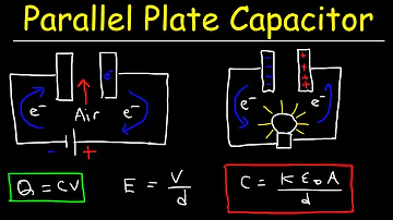
One kind of electrical component is the capacitor and the main purpose of this is to store the energy in an electrical charging form and produce a potential difference similar to a mini rechargeable battery between its two plates. Capacitors are available from very small to large in various shapes, but the purpose of all these is the same as electrical charge storage. Two metal plates that are isolated electrically through the air or good insulating material such as ceramic, plastic, mica, etc. are used in a capacitor. It is known as a dielectric for this insulating material. A description of the parallel plate capacitor and its operation is discussed in this article.
I. Features
1. Construction
The construction of this capacitor can be done with the help of metal plates otherwise metalized foil plates. These are arranged at an equal distance in parallel with each other. The two parallel plates are attached to the power supply in the capacitor. If the capacitor's primary plate is attached to the battery's +Ve terminal, then it gets a positive charge. Similarly, it receives a negative charge when the second plate of the capacitor is attached to a negative battery terminal. So, due to the attraction charges, it stores the energy between the plates.

2. Circuit
For charging the capacitor, the following circuit of the parallel plate capacitor is used. 'E' is the capacitor in this circuit,' V0'is the potential discrepancy, and' K 'is the switch.
Once the main such as 'K' is closed, the electron flow begins flowing in the direction of the battery's +Ve terminal. But the electron flow will be from the end of the battery to the end of + Ve.
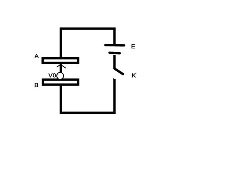
The electrons flow into the battery in the direction of the positive end, after which they continue to flow into the plate2. These two plates will receive charges like this, where one plate will receive a positive charge and the second plate will receive a negative charge.
Once the capacitor receives a potential change in the exact quantity of the battery, this process will proceed. Once this method ceases, the capacitor stores electrical charge, including the potential difference, as well. The charge can be written as Q = CV in the capacitor.
3. Capacitance
The direction of the electrical field is nothing but the flow of the positive test charge. The weakness of the body is known as capacitance and can be used to store electric energy. Similarly, a capacitor includes its capacitance, two metal plates with area 'A' are included in the parallel plate capacitor, and these are separated by the 'width.' It is possible to display the parallel plate capacitor formula below.
C = k*ϵ0*A*d
Where,
‘ϵo’ is the permittivity of space
‘k’ is the dielectric material’s relative permittivity
‘d’ is the partition between the two plates
‘A’ is the area of two plates
4. Derivation
The capacitor with two plates arranges in parallel is shown below.
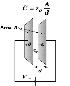
The first plate has a charge of '+ Q' in the capacitor and the second plate has a charge of '- Q'. With 'A' and the width, the area between these plates can be denoted (d). In this case,' d' is smaller than the plate area (d<<A). If the whole charge on the first plate is 'Q' & 'A' is the plate field, then the surface charge density can be extracted as:
σ =Q/A
Similarly, if the entire charge is'-Q 'on the second plate & the area of the plate is' A 'on the second plate, then the surface charge density can be extracted as:
σ = -Q/A
You may break the regions of this capacitor into three divisions, such as area1, area2, and area3. Area 1 is on the right of the second plate, area 2 is between the planes, and area 3 is on the right of the second plate. In the region around the capacitor, the electric field can be measured. The electric field is consistent here & its direction is from the plate +Ve to the plate-Ve.
The potential difference is determined in the condenser by multiplying the space between the electric field planes, which can be derived as:
V = Exd = 1/ε(Qd/A)
The capacitance of the parallel plate can be derived as C = Q/V = εoA/d
The capacitance of a parallel plate capacitor with 2 dielectrics is shown below. Every region of the plate is Am2 and is separated by a d-meter gap. K1 & k2 are the two dielectrics, so the capacitance would be like the following.
The main half of the capacitor width capacitance is d/2 = C1=> K1Aϵ0/ d/2=> 2K1Aϵ0/d
Similarly, the capacitance of the capacitor's next half is C2 = 2K2Aϵ0/d
Once these two capacitors are linked in sequence, the net capacitance: Ceff= C1C2/C1+C2= 2Aϵ0/d( K1K2/ /K1+K2) will be associated.
II. Working Principle
We know that we can supply a capacitor plate with a certain amount of electric charge. If we give more energy, then the potential increases so that it contributes to an outflow in the charge. Once plate 2 is arranged next to plate 1 that receives a positive charge, this plate 2 will be supplied with a negative charge.
If we get plate2 and it is put next to plate1, it is possible to supply negative energy through plate2. This negatively charged plate is closer to the plate that has been positively charged. If plate1 & plate2 have charges, the negative charge on plate2 on the first plate would reduce the potential difference.
The positive charge on the second plate would, alternatively, increase the potential variation on the first plate. The negative charge on plate 2 will have an extra effect, however. Therefore, it is possible to charge more on plate 1. Therefore, because of the negative charges on the second plate, the theoretical difference would be smaller.
III. Applications
The following are the applications of the parallel plate capacitor.
By connecting multiple capacitors in a circuit in parallel, more energy would be stored since the resulting capacitance is the number of individual capacitances of all the capacitor types inside the circuit.
In DC power supplies, parallel plate capacitors are used to process the O/P signal and eliminate the AC ripple.
Using inductive loads, the capacitor banks for energy storage can be used in PF(power factor) correction.
These are used for regenerative braking in large vehicles in the automotive industry.
 UTMEL
UTMEL
We are the professional distributor of electronic components, providing a large variety of products to save you a lot of time, effort, and cost with our efficient self-customized service. careful order preparation fast delivery service
How does a parallel plate capacitor work?
The simplest design for a capacitor is a parallel-plate, which consists of two metal plates with a gap between them: electrons are placed onto one plate (the negative plate), while an equal amount of electrons are removed from the other plate (the positive plate). Capacitors function a lot like rechargeable batteries.
What is the principle of parallel plate?
The two plates of parallel plate capacitor are of equal dimensions. They are connected to the power supply. The plate, connected to the positive terminal of the battery, acquires a positive charge. On the other hand, the plate, connected to the negative terminal of battery acquires a negative charge.
What happens to the charge on a parallel plate capacitor?
Differentiate between electrical potential and potential difference. potential difference is the change in electric potential between two points in space. What happens to the charge on a parallel-plate capacitor if the potential difference doubles? The charge on each plate doubles.
What is meant by the capacitance of a parallel plate capacitor?
The ability of a capacitor to store electric charge between its plates is its capacity or capacitance. DEFINITION. The capacitance of a capacitor is defined as: "The ratio of electric charge stored on any one of the plates of capacitor to potential difference between the plates.
How do you find the capacitance of a parallel plate capacitor?
The capacitance of a parallel plate capacitor is C=ϵ0Ad C = ϵ 0 A d , when the plates are separated by air or free space.
 AI Server MLCCs: Why NVIDIA Rubin Racks Require Over 600,000 CapacitorsUTMEL02 June 20261727
Next-generation AI servers like NVIDIA's Rubin architecture require over 600,000 MLCCs per rack due to extreme power densities exceeding 120kW. This transition from GB300 demands high-capacitance, low-ESR capacitors with X7R/X7S dielectrics to handle intense transient responses and thermal loads, forcing procurement teams to navigate extended 24-week lead times for these specialized components.
Read More What is Feedthrough Capacitor?UTMEL06 November 202141083
Hello, everyone. I am Rose. Today I will introduce the feedthrough capacitor to you. The feedthrough capacitor is a three-terminal capacitor that is used to reduce high frequencies. The feedthrough capacitor, unlike regular three-terminal capacitors, is directly installed on the metal panel, resulting in a lower grounding inductance and a negligible effect on the lead inductance.
Read More Detailed Explanation About Twenty Kinds of CapacitorUTMEL08 November 20219159
Hello everyone, I am Rose. Today I will introduce 20 kinds of capacitor to you. I will illustrate them in three or four aspects: Structure, features, Usages, advantages and disadvantages.
Read More What is a Polypropylene Capacitor?UTMEL08 November 202121507
A polypropylene capacitor is a kind of capacitor with a very stable electric capacity. It is often used in applications requiring very precise capacitance and can replace most polyphenylene or mica capacitors.
Read More What is the Difference between MOM, MIM and MOS Capacitors?UTMEL17 April 202569668
This article mainly introduces the structure, principle, advantages and disadvantages of MOM, MIM and MOS capacitors and the difference between them.
Read More
Subscribe to Utmel !
![MIKROE-4905]() MIKROE-4905
MIKROE-4905MikroElektronika
![STEVAL-CCA058V1]() STEVAL-CCA058V1
STEVAL-CCA058V1STMicroelectronics
![DEV-18721]() DEV-18721
DEV-18721SparkFun Electronics
![MIKROE-4915]() MIKROE-4915
MIKROE-4915MikroElektronika
![MIKROE-4888]() MIKROE-4888
MIKROE-4888MikroElektronika
![MIKROE-4828]() MIKROE-4828
MIKROE-4828MikroElektronika
![EVAL-ADUM4165EBZ]() EVAL-ADUM4165EBZ
EVAL-ADUM4165EBZAnalog Devices Inc.
![FSP-PIC18-Q10-ISO26262]() FSP-PIC18-Q10-ISO26262
FSP-PIC18-Q10-ISO26262Microchip Technology
![FBP-PIC16F184XX-ISO26262]() FBP-PIC16F184XX-ISO26262
FBP-PIC16F184XX-ISO26262Microchip Technology
![LPC5536-EVK]() LPC5536-EVK
LPC5536-EVKNXP USA Inc.
