
 Product
 Brand
Brand Articles
 Tools
Tools
DC Bias Characteristic of a Capacitor: Why MLCC Capacitance Drops Under Voltage
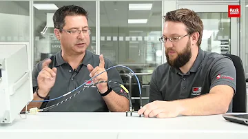
#askLorandt explains: Influence of DC-Bias on Ceramic Filter Capacitors

An MLCC’s marked capacitance is measured under benign test conditions, but its effective capacitance can drop significantly once DC voltage is applied.
Catalog
The Mechanism: Ferroelectric Class II Dielectrics Under Field
Class I vs Class II: C0G/NP0 Barely Moves While X7R, X5R, and Y5V Drop
Where DC Bias Loss Bites: Decoupling, DC-DC Output, and RC Filters
Stacking the Deratings: Bias Plus Temperature, Aging, and Tolerance
Mitigation: Case Size, Rated Voltage, Dielectric, and More Devices
What the DC Bias Characteristic Is
The DC bias characteristic describes how the capacitance of a ceramic capacitor changes as a steady DC voltage is applied across its terminals. As that bias voltage rises toward the rated voltage, the effective capacitance of a Class II ceramic part drops below its marked value. The part is not faulty and nothing has broken; this is a normal, measurable, and reversible property of the dielectric material.
The reason the nameplate and the operating value diverge comes down to how parts are measured. A capacitor is characterized at a small AC test signal with little or no DC bias applied, which is the value printed on the reel and in the part number. Your circuit, by contrast, holds the capacitor at a real operating voltage. Once that bias is present, the measured AC capacitance the circuit actually sees can be substantially lower than the catalog figure. The gap is widest for high-capacitance-density parts operating near their rated voltage, and it is the single most common reason a ceramic capacitor underperforms expectations.
The practical takeaway is simple: treat the marked value as a starting point measured under benign conditions, not as the capacitance delivered on a biased rail. The real number for a specific part comes from that part's derating curve.
The Mechanism: Ferroelectric Class II Dielectrics Under Field
Class II ceramic dielectrics are built on ferroelectric materials, typically barium-titanate-based ceramics chosen because they pack an enormous amount of capacitance into a small volume. That high permittivity is exactly what makes them sensitive to bias. In a ferroelectric material the effective permittivity is not constant; it depends on the strength of the internal electric field. As applied voltage drives the field higher, the dielectric domains become progressively harder to polarize further, the effective permittivity falls, and capacitance falls with it.
Field strength, not voltage alone, is what the dielectric responds to. Field is voltage divided by the thickness of each dielectric layer, so two parts at the same applied voltage can experience very different fields depending on how their layers are built. This is why the mechanism and the cure are linked: anything that lowers the field for a given working voltage softens the loss.

DC-bias loss is driven by electric field inside the dielectric, so thinner high-density MLCC layers can lose more capacitance at the same applied voltage.
Crucially, the effect is reversible. When the bias is reduced, the permittivity rises again and the capacitance recovers. Nothing is permanently consumed; the dielectric simply delivers less capacitance while it is held under field. That distinguishes DC-bias loss from aging, which is a slow, separate drift discussed later.
Why thinner, higher-density parts derate harder
The race for ever-smaller, higher-value MLCCs is won by making the internal dielectric layers thinner and stacking more of them. Thinner layers raise capacitance density, but for the same working voltage they also raise the field across each layer, which is precisely the condition that drives more loss. As a result, two parts with the same marked capacitance and rated voltage can derate quite differently if one achieves its value in a smaller case with thinner layers. The manufacturer curve for the exact ordering part is the only reliable way to see how far that trade has been pushed.
Class I vs Class II: C0G/NP0 Barely Moves While X7R, X5R, and Y5V Drop
Ceramic dielectrics split into two families with very different bias behavior. Class I dielectrics, of which C0G (also labeled NP0) is the best known, are paraelectric and essentially linear. Their permittivity barely changes with field, so they are stable under DC bias and over temperature. The trade-off is low capacitance density: a C0G part is physically large for its value.
Class II dielectrics such as X7R, X5R, and Y5V are the ferroelectric, high-density materials described above. They offer far more capacitance per unit volume but trade that for sensitivity to both bias and temperature. The sensitivity broadly increases as you move from X7R toward Y5V; the more aggressively a dielectric chases capacitance density, the more it tends to give up under field and heat.
The design cue follows directly from the table. When the application needs a value that must hold steady, such as a timing network, a precision RC filter, or a resonant tank, Class I earns its larger footprint. When the job is bulk decoupling and the budget is board area, Class II is the practical choice, provided the bias loss is accounted for rather than ignored.
Where DC Bias Loss Bites: Decoupling, DC-DC Output, and RC Filters
The loss matters wherever a design depends on a capacitor actually holding its rated value while biased. Three places show it most clearly.
In decoupling and bulk energy storage, the effective capacitance on the rail can sit well under the nameplate, which means the charge reservoir buffering load transients is smaller than the schematic implies. A bank sized purely from marked values may sag more than expected during current spikes.
On a DC-DC converter output, lower effective output capacitance raises output ripple and can shift the control loop's behavior, because the compensation was likely designed around an assumed output capacitance. Less capacitance than planned can erode phase margin and degrade transient response.
In RC and signal filters, capacitance sets the cutoff frequency. If the real biased capacitance is lower than the marked value, the corner frequency moves upward, so a filter intended to roll off at one frequency rolls off higher. The direction is always the same: less effective capacitance pushes the filter toward letting more through. The size of the shift depends entirely on the specific part and its operating point, which is why the next step is reading the curve rather than assuming a figure.
How to Read a DC-Bias Derating Curve
Every Class II MLCC series that matters comes with a DC-bias derating curve, and reading it is straightforward once you know the layout. The horizontal axis is the applied DC voltage, sometimes shown as an absolute voltage and sometimes as a percentage of rated voltage. The vertical axis is the change in capacitance, usually as a percentage relative to the value at zero bias.
To use it, enter the curve at your circuit's operating voltage on the horizontal axis, read up to the line for your exact part, and read across to the capacitance change. That value, applied to the marked capacitance, is the bias-derated capacitance you should design with. The curve is specific to the part: case size, rated voltage, and dielectric all change its shape, so a curve for one ordering code does not transfer to another even at the same nominal value.
For numbers you can trust, the most reliable route is the manufacturer's own characteristic viewer or simulation tool, where you select the exact part and the tool plots effective capacitance versus bias for that device. Murata's SimSurfing and the KEMET/YAGEO K-SIM tool both do this. Pull the curve for your exact ordering part and read the value at your real rail voltage.

To estimate usable capacitance, read the manufacturer’s DC-bias curve at the circuit’s real operating voltage, then apply the percentage loss to the marked value.
Stacking the Deratings: Bias Plus Temperature, Aging, and Tolerance
DC bias is only one of several effects that reduce real capacitance, and worst-case design has to combine them rather than treat bias in isolation. Temperature changes the capacitance of Class II parts according to their temperature characteristic. Aging causes Class II ceramics to lose capacitance slowly over time as the crystal structure relaxes after manufacture, a drift that resets if the part is heated above its Curie point and then begins again. Initial tolerance sets how far the part can start from its nominal value before any of these effects apply.
The effective capacitance your circuit can rely on is the marked value reduced by all of these together at the relevant operating point, not by bias alone. A part that looks comfortable on the bias curve can still fall short once temperature, aging, and tolerance are stacked on top.
| Factor | Direction of effect | Reversible? | Where to find the number |
|---|---|---|---|
| DC bias | Reduces capacitance as voltage rises | Yes, recovers when bias falls | Part-specific DC-bias derating curve |
| Temperature | Shifts capacitance per the temperature code | Yes, follows temperature | Temperature characteristic curve for the series |
| Aging | Slow downward drift over time | Resets only by heating above Curie point | Aging rate in the series datasheet |
| Initial tolerance | Sets starting spread around nominal | Fixed at manufacture | Tolerance code in the part number |
The practical workflow is to read the bias-derated value from the curve, then layer on the temperature characteristic for your operating range, the aging loss over the design life, and the tolerance band, to land on a defensible worst-case effective capacitance.
Mitigation: Case Size, Rated Voltage, Dielectric, and More Devices
DC-bias loss cannot be eliminated from Class II parts, but several levers reduce it, each with a trade-off worth weighing against board area and cost in space.
A larger case size for the same value generally derates less, because the dielectric layers can be thicker and the field per layer lower at the same voltage. A higher rated-voltage part moves the operating point further down its own curve, so the percentage of rated voltage in use is smaller and the loss is gentler. Switching to a lower-k dielectric or to Class I (C0G/NP0) trades density for stability and largely sidesteps the problem where the value is small enough to be practical. Finally, placing more devices in parallel raises the combined effective capacitance and rebuilds the margin lost to bias.
| Option | Why it helps | Trade-off |
|---|---|---|
| Larger case size | Thicker layers lower the field for the same voltage | Consumes more board area |
| Higher rated voltage | Operating point sits lower on the derating curve | Often larger and lower density for the value |
| Lower-k or Class I dielectric | Far less bias sensitivity, stable value | Much lower capacitance density |
| More devices in parallel | Rebuilds effective-capacitance margin | More placements and board space |
The exact gain from any of these is part-specific, so confirm the improvement on the candidate part's curve or tool rather than assuming a fixed benefit. The same nominal value in a different case size or voltage rating can behave very differently under bias, which is exactly the lever these options exploit.
Frequently Asked Questions
Does C0G/NP0 also lose capacitance under DC bias?
Effectively no. Class I dielectrics like C0G/NP0 are paraelectric and nearly linear, so their capacitance is stable under bias. That stability is the reason to choose them for timing and precision filters, at the cost of much lower capacitance density.
Why does my circuit simulator not show this capacitance loss?
A standard simulator treats a capacitor as an ideal component with a fixed value and does not model the dielectric's bias dependence. To see the real behavior, use a manufacturer characteristic viewer or simulation tool that includes the part's measured DC-bias data, such as Murata SimSurfing or KEMET K-SIM.
Does choosing a higher voltage rating eliminate the problem?
It reduces it but does not remove it. A higher-rated part operates at a smaller fraction of its rated voltage, which places it lower on the derating curve, so the loss is gentler. The part is usually larger or lower density for the same value, and you should still confirm the result on its curve.
Is a larger case size always better for DC-bias performance?
For the same value and dielectric, a larger case generally derates less because the layers can be thicker and the field lower. It is not free, since it costs board area, and the actual difference depends on the specific parts, so compare their curves before deciding.
How much capacitance do I actually lose at my operating voltage?
That depends entirely on the exact part, its case size, rated voltage, and dielectric. There is no universal figure to apply. Read the loss from the manufacturer's derating curve for your ordering part at your operating voltage, or plot it in the manufacturer's tool.
Is the loss permanent, or does the capacitance come back?
It is reversible. The capacitance falls only while the bias is applied and recovers when the voltage is reduced. This is distinct from aging, which is a slow, separate drift over time.
Does the DC bias characteristic apply to film, tantalum, or aluminum electrolytic capacitors?
The strong voltage-dependent loss described here is a property of Class II ceramic dielectrics. Film capacitors are very stable with bias, and tantalum and aluminum electrolytics have their own voltage and frequency behaviors that differ from this ferroelectric mechanism, so do not assume a ceramic curve applies to them.
How can I confirm the effective capacitance for my rail before finalizing the design?
Find the derating curve or open the manufacturer tool for the exact part, enter the operating voltage to get the bias-derated value, then combine that with the temperature characteristic for your range, the aging loss over life, and the initial tolerance to reach a worst-case effective capacitance.
Sources and Further Reading
Murata Ceramic Capacitor technical library explains how MLCC capacitance changes with applied DC voltage and temperature and links each series to its own documentation; the general material describes behavior, while exact figures still come from the specific part.
Murata SimSurfing characteristic viewer lets you plot effective capacitance versus DC bias for a chosen Murata part, so numbers come from the part itself; it covers Murata devices, so use the matching tool for other makers.
TDK ceramic capacitors product center confirms dielectric-class behavior and that Class II MLCC derates with bias and temperature, with per-series datasheets and curves that you must consult for any specific value.
KEMET / YAGEO K-SIM simulation tool simulates capacitance versus applied DC voltage for specific ceramic parts and shows the curve for a chosen device; results are part-specific, not a generic rule.
Samsung Electro-Mechanics MLCC technical library documents DC-bias and temperature characteristics of Class II MLCC at the series level; useful for class behavior, with magnitudes tied to each part.
IEC 60384 ceramic capacitor standards reference defines the dielectric-class framework behind Class I and Class II codes such as C0G/NP0 and X7R/X5R/Y5V; it standardizes terminology rather than predicting any part's bias loss.
 UTMEL
UTMEL
We are the professional distributor of electronic components, providing a large variety of products to save you a lot of time, effort, and cost with our efficient self-customized service. careful order preparation fast delivery service
1. What is the definition of DC bias voltage?
The DC bias voltage refers to the voltage that should be set between the base-emitter and the collector-base when the transistor is in the amplifying state in the transistor amplifier circuit.
2. What is the relationship between ceramic capacitor capacity and DC bias voltage?
The capacitance of Y5V dielectric ceramic capacitors varies greatly with the DC bias voltage. When the capacitance decreases from 100% of the unbiased capacitance to the DC bias voltage under the rated voltage, the percentage of the rated capacitance cannot be obtained. Twenty-five, that is to say, the capacitance of 10μF is only less than 2.5μF at rated voltage. At high temperature, since the capacitance has dropped to a very low level, the capacitance at this time does not change much with the DC bias voltage.
Although the capacitance of X7R dielectric ceramic capacitors varies greatly with DC bias voltage, it is much better than Y5V.
3. What is bias voltage what is forward bias voltage?
Considering the voltage as the coordinate axis, there is no offset when Y=0,
The voltage is greater than 0 volts, and Y is positive, called forward bias.
Voltage is less than 0 volts, and Y is negative, called reverse bias.
 AI Server MLCCs: Why NVIDIA Rubin Racks Require Over 600,000 CapacitorsUTMEL02 June 20261792
Next-generation AI servers like NVIDIA's Rubin architecture require over 600,000 MLCCs per rack due to extreme power densities exceeding 120kW. This transition from GB300 demands high-capacitance, low-ESR capacitors with X7R/X7S dielectrics to handle intense transient responses and thermal loads, forcing procurement teams to navigate extended 24-week lead times for these specialized components.
Read More for Liquid Cooling Environments") Thermal Management in AI Servers: Specifying Class 2 MLCCs (X7R/X7S) for Liquid Cooling EnvironmentsUTMEL13 July 202630
Thermal Management in AI Servers: Specifying Class 2 MLCCs (X7R/X7S) for Liquid Cooling EnvironmentsUTMEL13 July 202630Explore how the transition from traditional air-cooling to liquid cooling (direct-to-chip and immersion) in high-density AI server racks alters component thermal profiles. Focus on why design engineers are increasingly specifying Class 2 MLCCs (X7R and X7S dielectrics) over standard X5R variants to prevent thermal degradation near the liquid cooling microchannels. Explain how these capacitors mitigate acoustic noise and voltage bias degradation under heavy workloads. Provide sourcing advice for high-reliability passives via UTMEL during this high-demand memory and passive component super-cycle.
Read More What is Feedthrough Capacitor?UTMEL06 November 202141102
Hello, everyone. I am Rose. Today I will introduce the feedthrough capacitor to you. The feedthrough capacitor is a three-terminal capacitor that is used to reduce high frequencies. The feedthrough capacitor, unlike regular three-terminal capacitors, is directly installed on the metal panel, resulting in a lower grounding inductance and a negligible effect on the lead inductance.
Read More Detailed Explanation About Twenty Kinds of CapacitorUTMEL08 November 20219164
Hello everyone, I am Rose. Today I will introduce 20 kinds of capacitor to you. I will illustrate them in three or four aspects: Structure, features, Usages, advantages and disadvantages.
Read More What is a Polypropylene Capacitor?UTMEL08 November 202121524
A polypropylene capacitor is a kind of capacitor with a very stable electric capacity. It is often used in applications requiring very precise capacitance and can replace most polyphenylene or mica capacitors.
Read More
Subscribe to Utmel !
![IS31FL3748-QFLS4-EB]() IS31FL3748-QFLS4-EB
IS31FL3748-QFLS4-EBLumissil Microsystems
![SI8946ISO-KIT]() SI8946ISO-KIT
SI8946ISO-KITSkyworks Solutions Inc.
![SI8941ISO-KIT]() SI8941ISO-KIT
SI8941ISO-KITSkyworks Solutions Inc.
![MIKROE-4907]() MIKROE-4907
MIKROE-4907MikroElektronika
![MIKROE-4885]() MIKROE-4885
MIKROE-4885MikroElektronika
![MIKROE-4926]() MIKROE-4926
MIKROE-4926MikroElektronika
![REF35EVM]() REF35EVM
REF35EVMTexas Instruments
![MIKROE-4990]() MIKROE-4990
MIKROE-4990MikroElektronika
![MIKROE-4983]() MIKROE-4983
MIKROE-4983MikroElektronika
![MIKROE-4985]() MIKROE-4985
MIKROE-4985MikroElektronika
