
 Product
 Brand
Brand Articles
 Tools
Tools
Diodes Tutorial: How to Test Diodes?
How does a Diode work ?
A diode is a fundamental electronic component crafted from semiconductor materials. While traditionally made from silicon, selenium, or germanium, modern electronics have seen the rise of advanced wide-bandgap materials like Silicon Carbide (SiC) and Gallium Nitride (GaN). These newer materials enable diodes to operate at higher voltages, temperatures, and frequencies, making them crucial for next-generation technologies.
The defining characteristic of a diode is its unidirectional conductivity. When a forward voltage is applied across its terminals (anode and cathode), the diode conducts electricity, acting like a closed switch. Conversely, when a reverse voltage is applied, the diode blocks the current flow, behaving like an open switch. This simple yet powerful principle makes diodes indispensable in modern electronics.
As one of the earliest semiconductor devices, the diode remains a ubiquitous component in countless applications. From AC-to-DC rectification in power supplies to signal detection in communications and voltage regulation in all types of circuits, diodes are everywhere. They are essential building blocks, working alongside resistors, capacitors, and inductors to create the complex electronic systems that power our world, from simple household appliances to advanced industrial controls and electric vehicles.
(This article was originally published in 2020 and has been updated in October 2025 to include the latest advancements in diode technology and applications.)
Table of Contents
| I. Diode Structure |
| II. Diode Recognition & Modern Materials |
| III. Diode Characteristics |
| IV. How to Test Diodes |
| V. Diode Functions & Applications |
I. Diode Structure
A diode is fundamentally formed from a PN junction, which is created by joining P-type and N-type semiconductor materials. This junction is then enclosed in a package with electrode leads. Through a process called doping, a P-type semiconductor and an N-type semiconductor are fabricated on a single semiconductor substrate (most commonly silicon, but also germanium, SiC, or GaN). At their interface, a space charge region, known as the PN junction, is formed.
The electrode connected to the P-type region is called the anode, while the electrode connected to the N-type region is the cathode. Due to the unidirectional conductivity of the PN junction, conventional current flows from the anode to the cathode when the diode is forward-biased (turned on).
The circuit symbol for a diode clearly indicates this direction of current flow. The triangle points in the direction of forward current, from the positive anode to the negative cathode. In schematics, a diode is typically labeled with 'D' or 'VD'.

Figure 1: Diode circuit symbol, where the arrow indicates the direction of conventional current flow.
II. Diode Recognition & Modern Materials
Crystal diodes, also known as semiconductor diodes, come in a vast array of shapes, sizes, and materials, each tailored for specific functions. Common packages include glass-shell, plastic-encapsulated, and metal-shell diodes for low to medium power, as well as high-power bolt-shaped metal packages for industrial applications. You will also find miniature surface-mount diodes (SMD) on modern printed circuit boards.

Figure 2: A collection of different diode types and packages.
While traditional diodes are made from Silicon (Si) or Germanium (Ge), the field has evolved significantly. Today, wide-bandgap semiconductors like Silicon Carbide (SiC) and Gallium Nitride (GaN) are revolutionizing power electronics. These third-generation materials offer superior performance in high-power, high-frequency, and high-temperature environments, enabling more efficient and compact electronic devices.
| Material | Typical Forward Voltage | Key Characteristics |
|---|---|---|
| Germanium (Ge) | ~0.3V | Low forward voltage drop, but higher leakage current. Used in specific signal applications. |
| Silicon (Si) | ~0.7V | The most common and cost-effective material for general-purpose diodes and transistors. |
| Gallium Nitride (GaN) | ~1.0V - 3.0V+ | Excellent for high-frequency applications (e.g., fast chargers, RF amplifiers). High efficiency. |
| Silicon Carbide (SiC) | ~2.5V - 3.5V+ | Ideal for high-power, high-voltage, and high-temperature applications (e.g., electric vehicles, solar inverters). |
III. Diode Characteristics
Understanding a diode's key parameters is crucial for selecting the right component for a circuit. These are typically found in the manufacturer's datasheet.

Figure 3: A simple circuit illustrating forward and reverse bias conditions.
Maximum Forward Current (IFM): This is the maximum average current that can flow through the diode in the forward direction without causing damage. The actual operating current should always be safely below this limit.
Maximum Reverse Voltage (VRRM): This is the maximum voltage that can be applied across the diode in the reverse direction before it enters breakdown and potentially fails. It is a critical parameter for reliability, and a safety margin (e.g., selecting a diode with a VRRM at least twice the expected operating voltage) is recommended.
Maximum Operating Frequency (fM): For diodes used in high-frequency applications like signal detection or switching, this parameter indicates the highest frequency at which the diode can operate effectively.
Unidirectional Conductivity: This is the most fundamental characteristic. A diode allows current to flow easily from its anode to its cathode but blocks current flow in the opposite direction.
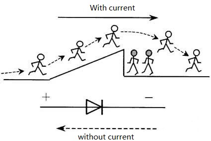
Figure 4: Diodes permit current flow in one direction only.
Identifying the anode and cathode is essential. The cathode is often marked with a line or band on the diode's body. For through-hole diodes, the cathode lead is sometimes shorter.

Figure 5: Common methods for identifying the anode and cathode.
Forward Voltage Drop & Volt-Ampere (I-V) Curves
A diode requires a minimum forward voltage to "turn on" and begin conducting significant current. This is known as the forward voltage drop (VF). As shown in the I-V curves below, the relationship between voltage and current in a diode is non-linear.
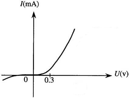
Figure 6: I-V curve for a Germanium (Ge) diode, showing a forward voltage drop of approximately 0.3V.

Figure 7: I-V curve for a Silicon (Si) diode, with a forward voltage drop of approximately 0.7V.
At the same temperature, silicon diodes exhibit much lower reverse leakage current compared to germanium diodes, which is a key reason for their widespread use. The non-linear I-V relationship confirms that diodes are non-linear semiconductor devices.
IV. How to Test Diodes
Testing a diode is a common task in electronics troubleshooting. Most modern digital multimeters (DMMs) have a dedicated diode test mode, which makes the process straightforward. This mode typically displays the diode's forward voltage drop.
1. Testing a Standard Diode with a Digital Multimeter
Set your multimeter to the diode test mode (often indicated by a diode symbol).
Connect the red (positive) probe to the anode and the black (negative) probe to the cathode. This is called forward-biasing the diode. A good diode will show a voltage reading between approximately 0.3V (for Germanium) and 0.8V (for Silicon).
Now, reverse the probes (red to cathode, black to anode). This is reverse-biasing the diode. A good diode should show an "OL" (Over Limit) or infinite reading, indicating that it is blocking current flow.
If you get a reading of "OL" in both directions, the diode is open. If you get a reading near zero in both directions, the diode is shorted. In either case, the diode is faulty and must be replaced.
2. Identifying Polarity
If the polarity isn't marked, you can use the diode test function to find it. The reading will show a voltage value only when the red probe is on the anode and the black probe is on the cathode. The end connected to the black probe when you get a valid reading is the cathode.
3. Testing Specific Diode Types
Light-Emitting Diodes (LEDs): When forward-biased in diode test mode, a good LED should light up dimly. The forward voltage of LEDs is higher than standard diodes, typically ranging from 1.8V for red LEDs to over 3.5V for blue or white LEDs. Your DMM must be able to supply this voltage to get a reading and light the LED.
Zener Diodes: A Zener diode tests like a normal diode in the forward direction. In the reverse direction, it will show "OL" unless your multimeter's test voltage exceeds the Zener's breakdown voltage (Vz), which is unlikely. Specialized testers are needed to verify the exact breakdown voltage.
Schottky Diodes: These will have a much lower forward voltage drop compared to standard silicon diodes, typically in the 0.15V to 0.45V range.
Infrared (IR) Diodes: An IR LED will not emit visible light when tested. However, you can use a smartphone camera (which can often see near-infrared light) to check if it is emitting when forward-biased. An IR receiving diode can be tested like a standard diode for forward and reverse resistance.
V. Diode Functions & Applications
The simple principle of unidirectional current flow allows diodes to perform several critical functions in electronic circuits.
1. Detection (Demodulation)
In radio communications, one of the primary functions of a diode is detection, or demodulating an amplitude-modulated (AM) signal. The diode effectively rectifies the high-frequency carrier wave, leaving the lower-frequency audio signal. An RC filter then smooths out the signal to recover the original audio information.

Figure 8: A simple diode detector circuit for AM radio.
2. Rectification
Rectification is the process of converting alternating current (AC) to direct current (DC), and it is one of the most common applications for diodes. This is the first step in almost every power supply.

Figure 9: A half-wave rectifier passes only half of the AC waveform.
A more efficient method is full-wave rectification, which uses four diodes in a bridge configuration to utilize both the positive and negative cycles of the AC waveform. This results in a smoother DC output that is easier to filter.
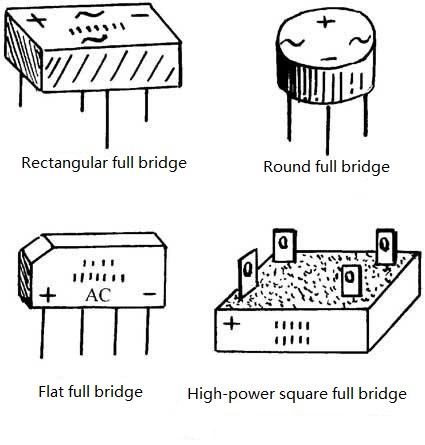
Figure 10: A packaged full-bridge rectifier.
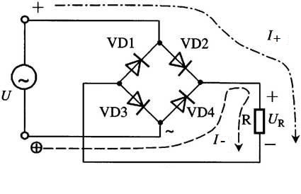
Figure 11: The circuit diagram for a full-wave bridge rectifier.
3. Voltage Regulation
Zener diodes are specifically designed to operate in the reverse breakdown region. They maintain a nearly constant voltage across their terminals over a wide range of reverse currents. This makes them ideal for creating simple voltage regulator circuits, providing a stable voltage reference for other components.
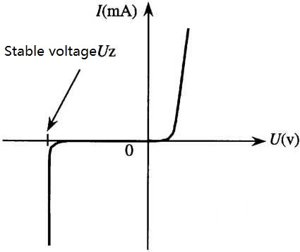
Figure 12: The I-V curve of a Zener diode, showing the stable reverse breakdown voltage (Vz).
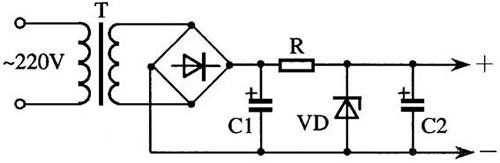
Figure 13: A simple parallel voltage regulator circuit.
4. Modern and Specialized Applications
Beyond these classic functions, diodes are at the heart of many modern technologies:
LED Lighting: Light-Emitting Diodes (LEDs) have revolutionized the lighting industry, offering unparalleled energy efficiency and lifespan.
Schottky Diodes: With their low forward voltage and fast switching, they are essential in high-efficiency power supplies and voltage clamping circuits.
SiC and GaN Diodes: These are critical components in power inverters for electric vehicles (EVs) and renewable energy systems (e.g., solar and wind), where high power and efficiency are paramount.
Laser Diodes: Used in everything from fiber optic communications and barcode readers to medical devices and industrial cutting tools.
Data Diodes: In cybersecurity, a data diode is a hardware device that allows data to flow in only one direction, providing a robust physical barrier to protect critical networks from external intrusion.
Conclusion
From its humble beginnings as a simple semiconductor device to its role as a key enabler of modern high-power and high-frequency electronics, the diode remains a cornerstone of the field. While the fundamental principles of silicon and germanium diodes still hold true, the landscape has been transformed by the advent of wide-bandgap materials like SiC and GaN. These innovations are paving the way for more efficient, compact, and robust electronic systems, driving progress in sustainable energy, transportation, and communications. Understanding the structure, characteristics, and diverse applications of diodes is more essential than ever for any electronics enthusiast, student, or professional.
Further Reading:
 UTMEL
UTMEL
We are the professional distributor of electronic components, providing a large variety of products to save you a lot of time, effort, and cost with our efficient self-customized service. careful order preparation fast delivery service
How do you check a diode?
A diode rating can be determined by its color pattern. Diodes allow conduction of electric current in one direction while blocking current from the reverse direction. Diodes come with colored stripes that help you read the value on the diode.
Can you test a diode in circuit?
A diode is a bipolar semiconductor that only allows current to pass in one direction. The positive terminal of a diode is called the anode, and the negative terminal is called the cathode. You can damage a diode by exceeding its rated voltage or current values. ... You can test a diode using a multimeter.
Can a diode go bad?
Although diodes rarely fail, it can happen if they are exposed to voltage or current above their rated limits. Unsolder one leg of the diode if it is part of a circuit, otherwise the other components in the circuit may affect the results of the test.
What causes a diode to fail?
The common reasons for a diode failure are excessive forward current and a largereverse voltage. Usually, large reverse voltage leads to a shorted diode while overcurrent makes it fail open.
How do I know if a diode is bad?
A diode is reverse-biased when the positive (red) test lead is on the cathode and the negative (black) test lead is on the anode. The reverse-biased resistance of a good diode displays OL on a multimeter. The diode is bad if readings are the same in both directions.
 All You Need to Know About Rectifier CircuitUTMEL24 April 202517438
All You Need to Know About Rectifier Circuit
Read More 15 Key Elements of Diode SelectionUTMEL26 November 202118804
Hello everyone, I am Rose. Welcome back to the new post today. Diodes are one of the most common components in our circuit boards. So, what factors should be considered when selecting models?
Read More What is a PIN Diode?UTMEL04 February 202110082
While diodes with a simple PN junction are by far the most common type of diode in operation, in a variety of applications, other forms of diode may be used. The PIN diode is one type that is used for a number of circuits. In a variety of places, this diode type is used. For RF switching, the PIN diode is very fine, and the PIN structure in photodiodes is very useful as well.
Read More Microwave Diode: Introduction and TypesUTMEL07 January 202125557
Microwave diodes are diodes that work in the microwave frequency band. It is a solid-state microwave device. Microwave band usually refers to the frequency from 300 MHz to 3000 GHz. After the discovery of the point contact diode effect at the end of the 19th century, microwave diodes such as PIN diodes, varactor diodes, and Schottky diode tubes appeared one after another. Microwave diodes have the advantages of small size and high reliability, and are used in microwave oscillation, amplification, frequency conversion, switching, phase shifting and modulation.
Read More What Determines the Maximum Operating Frequency of a Diode?UTMEL29 June 202212794
Hello, wish you a wonderful day. In this essay, we first pose the following query: what determines the diode's maximum operating frequency? In regards to the solution, the first thing we need to understand is that the junction capacitance and the reverse recovery time of the diode are two distinct concepts. The charging and discharging times of the junction capacitance cannot match the reverse recovery time. You say that, why? Let's start by taking a look at these facts.
Read More
Subscribe to Utmel !
![MMZ1005S102CT000]() MMZ1005S102CT000
MMZ1005S102CT000TDK Corporation
![BLM18HD471SN1D]() BLM18HD471SN1D
BLM18HD471SN1DMurata Electronics
![BLM18KG601SH1D]() BLM18KG601SH1D
BLM18KG601SH1DMurata Electronics
![BLM15BC121SN1D]() BLM15BC121SN1D
BLM15BC121SN1DMurata Electronics
![MMZ2012S800AT000]() MMZ2012S800AT000
MMZ2012S800AT000TDK Corporation
![MMZ1608D121CTAH0]() MMZ1608D121CTAH0
MMZ1608D121CTAH0TDK Corporation
![NFM3DCC102R1H3L]() NFM3DCC102R1H3L
NFM3DCC102R1H3LMurata Electronics
![NFM31KC223R1H3L]() NFM31KC223R1H3L
NFM31KC223R1H3LMurata Electronics
![MMZ1608Y600BTA00]() MMZ1608Y600BTA00
MMZ1608Y600BTA00TDK Corporation
![MMZ1608B102CTD25]() MMZ1608B102CTD25
MMZ1608B102CTD25TDK Corporation


