
 Product
 Brand
Brand Articles
 Tools
Tools
Film Capacitors Explained: Types, Characteristics, and How to Choose
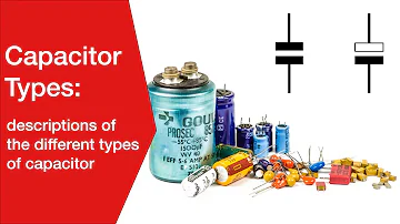
Capacitor Types: electrolytic, ceramic, tantalum, plastic film
Film capacitors sit in a comfortable middle ground between the bulk energy storage of electrolytics and the tiny footprint of ceramics. They are the parts engineers reach for when a circuit needs a stable, low-loss, non-polarized capacitor that behaves predictably over years of service. Instead of treating them as one generic component, it helps to think of the film family as a set of dielectric materials, each with its own personality, and to match that personality to the job in front of you.
What sets film capacitors apart
A film capacitor stores charge between metal electrodes separated by a thin sheet of plastic dielectric. Because that dielectric is an insulating polymer rather than an oxide layer grown on a polarized metal, the part is non-polarized and can sit happily in an AC path or a circuit where the voltage reverses. That single property already separates the family from aluminum and tantalum electrolytics.

The reputation of film capacitors rests on a handful of behaviours that engineers value. They tend to hold their capacitance closely over temperature and time, they dissipate little energy as heat at moderate frequencies, and they show low dielectric absorption, meaning they release stored charge cleanly rather than "remembering" a previous voltage. Many film constructions also handle voltage transients and ripple current gracefully. None of this comes for free: against a ceramic of the same value, a film part is usually physically larger, and against an electrolytic, it stores far less energy per unit volume. The family wins on stability and signal integrity, not on density.
The dielectric materials inside a film capacitor
The label on the part hides the most important decision, which is the polymer doing the insulating. Each film changes the trade between stability, temperature tolerance, and size.
Polypropylene (PP) is the workhorse of high-performance film. It offers very low loss, excellent stability, and strong behaviour under high voltage and high ripple, which is why it dominates power-electronics roles. Polyester, also called PET or by the trade name Mylar, trades some of that stability for a higher dielectric constant, so a PET part is more compact and more economical for a given value. The cost is weaker capacitance stability over temperature, which is acceptable in coupling, decoupling, and general-purpose timing where precision is not critical.
The specialty films extend the family into harder conditions. Polyphenylene sulphide (PPS) is prized for capacitance that barely moves across a wide temperature span, making it a candidate for precision filtering and circuits exposed to heat. Polyethylene naphthalate (PEN) tolerates elevated temperatures better than ordinary polyester and is often chosen where a compact part must survive a warm environment. Polystyrene and polycarbonate appear in legacy and niche precision designs, valued historically for stability, though availability has narrowed over the years. The qualitative ranking below is a starting frame; the exact temperature coefficients and tolerances always belong to a specific manufacturer datasheet.
| Dielectric | Capacitance stability | Temperature behaviour | Relative size for a given value | Where it typically fits |
|---|---|---|---|---|
| Polypropylene (PP) | Very high | Good, with a predictable negative drift | Larger | DC-link, snubber, audio, EMI/safety, high ripple |
| Polyester / PET (Mylar) | Moderate | Moderate, more drift than PP | Compact | Coupling, decoupling, general purpose |
| Polyphenylene sulphide (PPS) | High | Very flat across a wide range | Compact | Precision filtering, hot environments |
| Polyethylene naphthalate (PEN) | Moderate to high | Better high-temperature tolerance than PET | Compact | Compact parts in warm settings |

Treat this as a behavioural map rather than a spec sheet. Two PP parts from different makers can differ in voltage rating, ripple handling, and self-healing behaviour, so the named datasheet remains the authority on any number.
Film/foil versus metallized construction
Two parts can share the same dielectric and still behave differently because of how the electrodes are made. In a film/foil capacitor, separate sheets of metal foil act as the electrodes and are wound with the plastic film between them. In a metallized film capacitor, an extremely thin metal layer is vacuum-deposited directly onto the plastic, and that coated film is wound to form the part.
The metallized approach brings a property that genuinely changes reliability thinking: self-healing. If a localized weak spot in the dielectric breaks down, the high current density at the fault vaporizes the thin metal coating around it, isolating the defect and letting the capacitor keep working at a marginally reduced value rather than failing as a hard short. Film/foil parts cannot do this, but their thicker foil electrodes carry higher peak and pulse currents and tend to offer lower inductance, which matters in demanding pulse and high-frequency roles. The two styles therefore answer different questions, as summarized below.
| Construction | Electrode | Self-healing | Peak/pulse current handling | Typical reason to choose it |
|---|---|---|---|---|
| Film/foil | Separate metal foil | No | Higher | Pulse and high-current paths, lowest inductance |
| Metallized film | Metal deposited on film | Yes | Moderate | Reliability under occasional dielectric stress, compact size |
Characteristics that matter when you specify one
When an engineer weighs a film capacitor, a few properties carry most of the decision. Capacitance stability over temperature and time decides whether the part is suitable for timing, filtering, or precision analog work. Loss, often discussed through dissipation factor and series resistance (ESR), governs how much the part heats under ripple and how it behaves at frequency. Voltage handling covers both the steady working voltage and the ability to absorb transients without damage. Ripple-current capability sets how much AC the part can pass before self-heating becomes a problem, which is central to power roles.
Physical size and mounting style round out the picture, because a stable dielectric is only useful if the part fits the board and the thermal environment. Where exact figures are needed, the relevant temperature coefficient, tolerance, voltage derating curve, and ripple rating come from the manufacturer datasheet for the specific series, not from a general rule of thumb.
Choosing the right film capacitor for the job
A good way to choose is to start from the role and let the application pull you toward a dielectric and a construction, rather than starting from a part number. The mapping below reflects where each film commonly earns its place.
| Application | Common film choice | What the role demands |
|---|---|---|
| DC-link in power conversion | Metallized polypropylene | High ripple handling, stability, self-healing safety margin |
| Snubber across switches | Polypropylene, often film/foil for pulse duty | Fast voltage edges, high peak current, low loss |
| Audio signal path | Polypropylene | Low loss and low dielectric absorption for clean signal |
| EMI and line-filtering / safety positions | Polypropylene or polyester in safety-rated series | Predictable behaviour across line voltage; safety-rated parts only |
| Precision filtering and timing | PPS, or polystyrene in legacy designs | Tight, temperature-stable capacitance |
| General coupling and decoupling | Polyester / PET | Compact, economical, stability not critical |

A short selection checklist keeps the process repeatable:
Start from the electrical role: energy buffering, signal coupling, snubbing, or filtering.
Note the temperature range and how flat the capacitance must stay across it.
Estimate the ripple current and peak voltage the part must survive.
Decide whether self-healing reliability or maximum pulse current matters more, which points you to metallized or film/foil.
Confirm the working voltage and any safety positioning, then read the candidate series datasheet for the exact ratings.
For any role that touches the AC line or a safety function, the part must carry the appropriate safety-rated series designation from the manufacturer, and that status should be confirmed in the datasheet rather than assumed from the dielectric alone.
Trade-offs and pitfalls to plan around
The most common surprise is size. A film capacitor is physically larger than a ceramic of the same value, so high capacitance in a small footprint is simply not the family's strength, and there is a practical ceiling on how much capacitance a single film part offers before it becomes impractical. Where bulk energy storage is the goal, an electrolytic usually carries that load while a film part handles the high-frequency or high-ripple portion alongside it.
Voltage derating deserves respect. Running a film capacitor near its rated voltage, especially at elevated temperature or with significant ripple, shortens its useful life, so designers leave headroom and follow the derating guidance in the datasheet. It is also worth remembering that a charged power capacitor holds energy after the supply is removed; treat such a part as charged until it has been safely discharged. Finally, the gradual capacitance loss that comes with metallized self-healing is normal and benign in most roles, but in a precision circuit it is one more reason to favour a stable dielectric and a generous voltage margin.
Frequently asked questions
What is the practical difference between a PP and a PET film capacitor?
Polypropylene offers lower loss and tighter stability over temperature and time, which is why it dominates power, audio, and precision roles. Polyester (PET) is more compact and more economical for the same value but drifts more with temperature, making it a better fit for general coupling and decoupling where precision is not essential.
What is a PPS capacitor and when would I use one?
A PPS capacitor uses a polyphenylene sulphide dielectric whose capacitance stays unusually flat across a wide temperature range. It suits precision filtering, timing, and circuits that run warm, in situations where the stability justifies its cost relative to ordinary polyester.
What are the common types of film capacitors?
The family is usually grouped by dielectric: polypropylene (PP), polyester/PET, polyphenylene sulphide (PPS), and polyethylene naphthalate (PEN), with polystyrene and polycarbonate appearing in legacy and niche precision designs. Within each dielectric, parts are built as either film/foil or metallized film.
How does the self-healing property actually work?
In a metallized film part, the electrode is a very thin metal layer on the plastic. If a small dielectric flaw breaks down, the concentrated current vaporizes the metal around the fault and isolates it, so the capacitor keeps working at a slightly reduced capacitance instead of failing short.
Are film capacitors long-lived?
Within their rated voltage, temperature, and ripple limits they are generally durable and age gracefully. Lifetime depends heavily on operating conditions and the specific series, so the manufacturer datasheet, not a general claim, is the right reference for any expected-life figure.
What are the main disadvantages of film capacitors?
They are larger than ceramics for the same value, they top out at modest capacitance compared with electrolytics, and the higher-performance dielectrics cost more. They are chosen for stability and clean behaviour, not for energy density or smallest size.
Sources and references
Panasonic Industry film capacitors confirms the dielectric families Panasonic offers and the roles they position each series for; as a manufacturer catalog it presents its own portfolio rather than a neutral cross-vendor comparison.
TDK film capacitors confirms construction styles and application categories such as DC-link and snubber duty; the technical detail lives in individual series datasheets linked from each product page rather than the overview itself.
Vishay film capacitors confirms the distinction between film/foil and metallized parts and the safety-rated line-filter categories; ratings vary by series, so the specific datasheet remains the authority on numbers.
WIMA film capacitors confirms how dielectric choice maps to audio, power, and pulse roles; as a specialist supplier its framing reflects its own product range and not the whole market.
KEMET film capacitors confirms metallized self-healing behaviour and DC-link positioning; the descriptions are product-oriented, so design limits should be verified against the relevant datasheet.
Digi-Key film capacitor selection guidance provides cross-vendor framing for comparing dielectric types during selection; it summarizes general behaviour and points back to manufacturer documentation for exact specifications.
 UTMEL
UTMEL
We are the professional distributor of electronic components, providing a large variety of products to save you a lot of time, effort, and cost with our efficient self-customized service. careful order preparation fast delivery service
What are film capacitors used for?
Film capacitors are widely used because of their superior characteristics. This capacitor type is not polarized, which makes them suitable for AC signal and power use. Film capacitors can be made with very high precision capacitance values, and they retain that value longer than other capacitor types.
What is the preferred application of a film capacitor?
Most power capacitors, the largest capacitors made, generally use polypropylene film as the dielectric. PP film capacitors are used for high-frequency high-power applications such as induction heating, for pulsed power energy discharge applications, and as AC capacitors for electrical distribution.
What is the difference between ceramic and film capacitors?
In general, ceramic capacitors are somewhat non-linear in their frequency and voltage responses, compared to film capacitors. Both film caps and ceramic ones are non-polarized, so that isn't a difference.
Do film capacitors go bad?
Polyester film capacitors are generally quite reliable unless repeatedly pushed to their dielectric breakdown threshold, which should not ordinarily happen in normal use (you would typically expect that to happen only with large surges or lightning strikes) provided they were properly spec'd to begin with.
What's inside a film capacitor?
As the name suggests, the film/foil capacitor uses plastic films as dielectric and is placed inside two layers of electrodes made of aluminum foil. These interleaved layers are so structured that the metallic layers do not contact with each other. These capacitors can be either inductive or non-inductive.
 AI Server MLCCs: Why NVIDIA Rubin Racks Require Over 600,000 CapacitorsUTMEL02 June 20261724
Next-generation AI servers like NVIDIA's Rubin architecture require over 600,000 MLCCs per rack due to extreme power densities exceeding 120kW. This transition from GB300 demands high-capacitance, low-ESR capacitors with X7R/X7S dielectrics to handle intense transient responses and thermal loads, forcing procurement teams to navigate extended 24-week lead times for these specialized components.
Read More What is Feedthrough Capacitor?UTMEL06 November 202141083
Hello, everyone. I am Rose. Today I will introduce the feedthrough capacitor to you. The feedthrough capacitor is a three-terminal capacitor that is used to reduce high frequencies. The feedthrough capacitor, unlike regular three-terminal capacitors, is directly installed on the metal panel, resulting in a lower grounding inductance and a negligible effect on the lead inductance.
Read More Detailed Explanation About Twenty Kinds of CapacitorUTMEL08 November 20219157
Hello everyone, I am Rose. Today I will introduce 20 kinds of capacitor to you. I will illustrate them in three or four aspects: Structure, features, Usages, advantages and disadvantages.
Read More What is a Polypropylene Capacitor?UTMEL08 November 202121506
A polypropylene capacitor is a kind of capacitor with a very stable electric capacity. It is often used in applications requiring very precise capacitance and can replace most polyphenylene or mica capacitors.
Read More What is the Difference between MOM, MIM and MOS Capacitors?UTMEL17 April 202569667
This article mainly introduces the structure, principle, advantages and disadvantages of MOM, MIM and MOS capacitors and the difference between them.
Read More
Subscribe to Utmel !
![11028]() 11028
11028HEYCO PRODUCTS
![EMBAT945GSERRDK]() EMBAT945GSERRDK
EMBAT945GSERRDKIntel
![BEAGLEXM]() BEAGLEXM
BEAGLEXMTexas Instruments
![UBA2017DB1064598]()
![WSA1YR1000N]() WSA1YR1000N
WSA1YR1000NSchneider
![XR15715EVB]() XR15715EVB
XR15715EVBExar Corporation
![HQPACK100RB179]() HQPACK100RB179
HQPACK100RB179Infineon
![MAX17633AEVKITA#]() MAX17633AEVKITA#
MAX17633AEVKITA#Analog Devices
![DC2365A-E]() DC2365A-E
DC2365A-EAnalog Devices
![DC682A]() DC682A
DC682AAnalog Devices
