Introduction to buck, boost, and buck-boost converters
Boost Converters and Buck Converters: Power Electronics
| Topics covered in this article: |
| Ⅰ.What is buck converter? |
| Ⅱ.How does a buck converter work? |
| Ⅲ.What is boost converter? |
| Ⅳ.How does a buck converter work? |
| Ⅴ.What is buck-boost converter? |
Ⅰ.What is buck converter?
A buck converter (buck converter) is a DC-to-DC power converter that lowers the voltage from the source to the load (in drawing a smaller average current). It's a type of switching power supply (SMPS) with at least two semiconductors (a diode and a transistor, though modern buck converters often use a second transistor instead of a diode for synchronous rectification) and at least one energy storage element, such as capacitance, inductance, or a combination of the two.
Filters consisting of capacitors (often paired with inductors) are typically added to the output (load-side filter) and input (power-side filter) of this type of converter to reduce voltage ripple.
As DC-DC converters, switching converters (such as step-down converters) are more efficient than linear regulators. Linear regulators are less complicated circuits that reduce voltage by dissipating energy as heat. However, the output current will not be increased. Buck converters are extremely efficient (often greater than 90%), making them ideal for converting the computer's primary (large-capacity) power supply voltage (about 12 V) to the lower voltages required by USB, DRAM, and the CPU ( 5V, 3.3V or 1.8V, see PSU).
One of the most often used DC/DC converters is the step-down DC/DC converter, also known as Buck converter. The buck converter may reduce a greater DC voltage to a lower DC value, such as from 24V to 12V or 5V. The buck converter offers a wide range of applications, low losses, and great efficiency.
Ⅱ.How does a buck converter work?
In the tube that controls the power switch under the control of the pulse width modulation (PWM) signal, the VT of the step-down DC/DC converter is switched on and off (also called cut-off) alternately. PWM is analogous to a mechanical switch that closes and opens at a fast speed. Figure 1 depicts its functioning principle. Figures 1-1 and 1-2 depict the current path when VT is turned on and off, respectively. To make circuit analysis easier, the figure replaces the turning on and off of VT by the shutting and opening of switch S. When VT is activated (i.e., S is closed), the freewheeling diode VD is disabled, and the input voltage UI is applied to the left end of the energy storage inductor L, resulting in a voltage of (UI -UO). The energy stored in the inductor increases linearly as the current IL running through L increases. The inductor's induced electromotive force is left "+" and right "-." During this time, the input current (i.e., the inductor current I L) charges the filter capacitor C in addition to giving power to the load. The sum of the capacitor charging current I 1 and the load R L current I O is the inductor current I L.
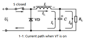

Figure 1: Busk DC/DC Converter Working Principle
The inductor L is detached from U I when VT is switched off (i.e. S is unplugged), as indicated in Figure 1-2. Because the current in the inductor cannot fluctuate abruptly, an induced voltage of left "-" and right "+" is generated on L to keep the current I L through the inductor constant. The freewheeling diode VD is turned on at this point, converting the magnetic field energy stored in L into electric energy, which continues to give power to the load through the loop formed by VD, while the inductor current I L declines linearly. At this point, the filter capacitor C's discharge current I 2 is superimposed over the inductor current I L to deliver power to the load R L. The total of the inductor current I L and the capacitor discharge current I 2 is the load current I O.
Tips
The buck converter is a forward converter that sends energy to the load when the power switch is turned on.
Figure 2-1 depicts the voltage and current waveforms of a step-down DC/DC converter. PWM is the pulse width modulation waveform, t ON is the power switch VT's on time, and t OFF is the power switch VT's off time. The switching time, T, is equal to the sum of t ON and t OFF, or T = t ON + t OFF. The duty cycle is the ratio of t ON to T, which is denoted by the letter "D," as in D=t ON /T.

Figure 2-1 voltage and current waveforms of a step-down DC/DC converter
The power switch tube VT's emitter voltage waveform is U E, and the collector current waveform is I C. The current waveform of the freewheeling diode VD is represented by I F. The filter inductor's current waveform is I L. When the power switch tube VT is turned on, the emitter voltage U E equals the input voltage U I, and when VT is turned off, the emitter voltage U E is zero. The inductor current increases linearly during the VT on-time of the power switch and falls linearly during the VT off-time. The collector current I C of VT and the current I F of the freewheeling diode VD combine to create the inductor current I L.
The average value of the filter inductor current I L equals the DC/DC converter's output current I O. The inductor ripple current is the difference between the peak and valley values in the inductor current waveform. To reduce output current ripple, L should be large enough to allow the DC/DC converter to operate in continuous mode. The ripple current should typically be around 20% of the rated output current.
The following are the properties of a step-down DC/DC converter.
1. U O is the output voltage.
2. The polarity of the output voltage U O and the input voltage U I are the same.
3. The maximum voltage that the power switch tube VT can handle is U CE =U I.
4. The maximum current I C of the power switch tube's collector VT =I O.
5. The freewheeling diode's average current VD I F =(1-D)I O.
6. U R =U I is the reverse voltage that the freewheeling diode VD carries.
7. Step-down Discrete components and PWM controllers can be used in DC/DC converters, or integrated circuit devices can be used. The LM2576, LM2596, and L4960 are examples of common integrated circuit products. The LM2576 peripheral circuit is the simplest of them all.
Ⅲ.What is boost converter?
A boost converter or a DC boost chopper is another name for a DC boost converter. It's a DC-DC converter that can boost voltage and has a greater output (load) voltage than the input (power) voltage. A switching power supply containing at least two semiconductor elements (a diode and a transistor) and at least one energy storage element is known as a boost converter (inductor). Filters built of capacitors (and occasionally inductors) are positioned at the input and output ends to reduce voltage ripple. It's used in a variety of applications, including automotive applications, power amplifier applications, adaptive control applications, battery power systems, consumer electronics, communication applications, battery charging circuits, heaters and welders, DC motor drives, power factor correction circuits, and distributed Power architecture systems.
Ⅳ.How does a buck converter work?
The tube that controls the power switch The pulse width modulation (PWM) signal controls the VT of the boost DC/DC converter, which is analogous to a mechanical switch that closes and opens at a high speed. Figure 3 depicts its functioning principle. Figures 3-1 and 3-2 depict the present routes when VT is turned on and off, respectively. The figure depicts the closure and opening of switch S to aid circuit analysis. It takes the place of VT's on/off switches.
When VT is switched on (i.e., S is closed), the input voltage U I is applied straight to both ends of the energy storage inductor L, and the freewheeling diode VD is turned off, as illustrated in Figure3-1. Because the voltage of U I is applied to L, the current I L of the inductor increases linearly, as does the energy stored in the inductor. The inductor's induced electromotive force is left "+" and right "-." During this time, the energy provided by the input current (i.e., the inductor current I L) is stored as magnetic field energy in the energy storage inductor L.
The filter capacitor C is discharged at the same time to give a current I O for the load R L, and the capacitor C's discharge current I 1 is equal to the load current I O.
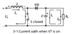
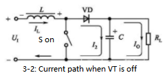
Figure 3: Boost DC/DC Converter Working Principle
Because the inductor current cannot vary abruptly when VT is switched off (i.e. S is disconnected), an induced voltage of left "-" and right "+" is generated on L to preserve the inductance, as shown in Figure 3-2. The present IL remains unchanged. The freewheeling diode VD is turned on at this point, and the induced electromotive force on L is connected in series with U I, converting the magnetic field energy stored in L into electric energy, which provides current to the load at a voltage greater than U I and charges the output filter capacitor C. The total of the capacitor charging current I 2 and the load current I O is the inductor current I L.
Tips
When the power switch is switched off, the boost converter, also known as a flyback converter, delivers energy to the load.
Figure 3-3 depicts the boost DC/DC converter's voltage and current waveforms. PWM is the pulse width modulation waveform, t ON is the power switch VT's on time, and t OFF is the power switch VT's off time. The switching phase is denoted by the letter T. The power switch tube VT's collector voltage waveform is denoted by U C. The collector current waveform of VT is I C. The current waveform of the boost diode VD is I F, and the current waveform of the inductor is I L. When the power switch tube VT is turned on, the collector voltage U C is zero; when the power switch tube VT is turned off, the collector voltage U C is equal to the output voltage U O. The inductor current increases linearly during the VT on-time of the power switch and falls linearly during the VT off-time. The collector current I C of VT and the current I F of the boost diode VD combine to create the inductor current I L.

Figure 3-3 boost DC/DC converter's voltage and current waveforms
The following are the features of a boost DC/DC converter.
1. It is called a boost converter because the output voltage is U O U I. U O =U I /(1-D) is the relationship between U O and U I, and the output voltage can be modified by adjusting the duty cycle D.
2. The polarity of the output voltage U O and the input voltage U I are the same.
3. The highest voltage that the power switch tube VT can withstand is U CE =U O.
4. VT I C =I O / VT I C =I O / VT I C =I O / VT I C =I O / VT I C =I O (1-D).
5. VD I F =I O is the average current of the boost diode.
6. The boost diode VD carries a reverse voltage U R =U O.
7. Step-up DC/DC converter integrated circuits include the LM2577 and MAX1599.
Ⅴ.What is buck-boost converter?
A buck-boost converter is a DC-DC converter with an output voltage that can be higher or lower than the input voltage. The buck-boost converter is similar to the flyback converter, except instead of a transformer, it uses a single inductor.
Buck-boost converters are two types of circuits with different topologies that both have a wide output voltage range, ranging from a voltage substantially higher (in absolute value) than the output voltage to a voltage near zero. The reverse architecture is a switching power supply with a circuit similar to a buck converter or a boost converter, with the output voltage polarity opposite the input voltage. The duty cycle of the switching power crystal can be used to change the output voltage. The other is a hybrid architecture that combines buck and boost converters.
The output voltage has the same electrical polarity as the input voltage and might be smaller or larger than the input value. This sort of non-inverting converter can employ switches instead of diodes and can share an inductor between the buck and boost converter sections. A four-switch buck-boost converter is also known as a four-switch buck-boost converter. Multiple inductors can be utilized, but like a SEPIC converter or a uk converter, just one switch is employed.
1.What is the difference between a buck converter and a buck regulator?
The buck converter converts the direct current into a lower voltage direct current. It has a constant transformation ratio.
Buck regulators are used to maintaining a constant DC output voltage for varying DC input voltages. So the transformation ratio here is constantly changing to keep the output voltage constant.
2.What is the role of the capacitor in a buck converter?
It is used to stabilize the voltage across the load and allow ripple current to pass through it, thereby maintaining a constant current on the load.
3.Why use LC instead of RC filter in a buck converter?
Inductors (L) and capacitors (C) are reactances that store electrical energy. The resistance (R) dissipates it as heat. The goal of the converter is to transfer as much power as possible from input to output in order to achieve high efficiency. This is achieved by first storing some power in the inductor and then transferring it to the output capacitor. When switching to output, the ratio of input to output conversion time is related to the input to output voltage, which affects the conversion.
 The Development Trends in the Field of Electronic Component ApplicationsUTMEL28 July 20233339
Electronic components form the backbone of all the technologies we see around today. Every innovative technology and flashy gadget we use has been fueled by these components. Moreover, electronic component applications expand to diverse fields and industries, including consumer electronics, healthcare, education, military, and similar others.
Read More Exploring the Strengths and Hurdles of Wide Bandgap Devices in Alternating Current Electric DrivesSaumitra Jagdale19 January 20242023
Wide-bandgap materials have emerged as pioneers in the era of power devices, altering the performance and efficiency of electronic systems. Silicon, the traditional semiconductor material, has limitations that become apparent as power requirements escalate. WBG materials, such as silicon carbide and gallium nitride, possess high switching frequency, low losses and high-temperature operating capability making them an ideal choice in power devices.
Read More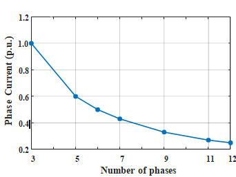 Revolutionizing Automotive Traction: A Comprehensive Review of Multiphase Drives for Next-Generation VehiclesUTMEL04 May 20232553
In recent years, the revolutionary development of power electronics and converters paved the way for more scope for research in multiphase drives.
Read More Unveiling the Magic Behind TWS Earbuds: An Analysis of Their Market, Working, and Core ComponentsUTMEL24 July 20233729
TWS (True wireless stereo) is one of the most advanced sound technologies of recent days. It provides awesome sound quality through Bluetooth Connection. From this little device, you can enjoy anything (movies, videos, etc...) wirelessly.
Read More Automatic Voltage Regulator: Ultimate Guide to Stable Power and Equipment ProtectionUTMEL06 May 20255493
This in-depth manual will explore the realm of automatic voltage regulators. We'll go over what they are, how they work, their important advantages, and factors to take into account while selecting one. By the conclusion, you'll see why an AVR is essential to modern operations and living, not simply a nice-to-have.
Read More
Subscribe to Utmel !
![M1504-D-3005-S]()
![3553T-E-632-SS]()
![M1945-D-2545-SS]()
![M0950-B-25-B]() M0950-B-25-B
M0950-B-25-BRAF
![3112T-F-440-AL]()
![M1423-3506-B]() M1423-3506-B
M1423-3506-BRAF
![1334T-8-SS]() 1334T-8-SS
1334T-8-SSRAF
![4194-1224-N]() 4194-1224-N
4194-1224-NRAF
![4082T-440-N]() 4082T-440-N
4082T-440-NRAF
![7557-A-440-B]() 7557-A-440-B
7557-A-440-BRAF


