
 Product
 Brand
Brand Articles
 Tools
Tools
How do Inductors Work?

Inductors Explained - The basics how inductors work working principle
Catalog
Ⅰ Introduction
Inductors are energy storage elements that convert electrical energy into magnetic energy for storage. They are fundamental passive electronic components found in virtually every electronic device, from smartphones to electric vehicles. Similar to a transformer, an inductor typically has a single winding, though its structure can vary significantly based on application requirements.
The structure of an inductor generally comprises a skeleton (bobbin), a winding (coil), a shield, packaging material, and often an iron core or magnetic core. An inductor stores electrical energy in the form of magnetic flux. When current flows through the conductor, a magnetic field is generated perpendicular to the direction of current flow. In its most basic form, an inductor can be as simple as a wire coil. By winding wires around a core, the inductance value can be significantly increased. The material characteristics of the magnetic core have a profound influence on the inductance value, and the characteristics of the inductance can be optimized through careful selection of core shape and material.
Inductors have important characteristics that engineers utilize to manage energy and control signals. The main characteristics of the inductor include:
Unlike the resistor, the electrical energy associated with the induced current is not dissipated as heat but is stored in the magnetic field;
When the inductor current is interrupted, the stored energy returns to the circuit;
The behavior of the inductor is frequency-dependent, with impedance increasing with frequency;
When the magnetic field stores the maximum energy it can accommodate, the inductor will "saturate." After saturation, increases in current do not strengthen the magnetic field, and excess electrical energy is dissipated as heat.
Utilizing these characteristics, inductors are commonly used in filter circuits, to manage energy flow in switching power conversion applications, in electromagnetic interference (EMI) suppression, signal processing, and increasingly in modern applications such as wireless charging, 5G communications, and electric vehicle power systems.
Ⅱ The Unit of Inductance
Since inductance was discovered by the American scientist Joseph Henry (1797-1878), the unit of inductance is named "Henry" in his honor. The unit of inductance is Henry (H). By definition, if a current with a rate of change of 1 ampere per second produces a back electromotive force (EMF) of 1 volt, the device or circuit has an inductance of 1 Henry. The symbol of the inductor is denoted by the capital letter L. The unit of inductance is H, mH (millihenry), and μH (microhenry). Their conversion relationship is: 1 H = 10³ mH = 10⁶ μH.
When a voltage is applied across the inductor, the rate of current rise is related to the voltage and the inductance value. A 1V potential across a 1H inductor will increase the current at a rate of 1A per second. The formula applicable here is:
V = L × (di/dt)
Alternatively, a current of 1A through a coil that produces a magnetic flux linkage of 1 Weber (Wb) means this coil has an inductance of 1H.
Inductors are classified as general inductors and precision inductors based on their tolerance specifications:
| Category | Precision Inductor | General Inductor | ||||
| Symbol | F | G | J | K | L | M |
| Tolerance | ±1% | ±2% | ±5% | ±10% | ±15% | ±20% |
Ⅲ What Does an Inductor Do?
1. The Role of Inductors in Alternating Current
When alternating current flows through an inductor, the inductor opposes changes in current flow. It doesn't allow the current to increase instantaneously but forces it to increase gradually. Similarly, when the AC power is disconnected, the inductor doesn't allow the current to drop instantly but causes it to decrease slowly.
This process can be clearly observed through the change in brightness of an incandescent lamp. In an AC circuit where inductors, incandescent lamps, and switches are connected in series, when the switch is closed, the incandescent lamp will not illuminate instantly but will gradually brighten from dim to full brightness. When the switch is opened, the incandescent lamp will not suddenly turn off but will fade from bright to dark. This entire process clearly demonstrates the working function of the inductor: to stabilize the current. Electric energy is converted into magnetic energy, and then magnetic energy is converted back into electric energy. In these two processes, the former represents the lamp transitioning from dark to bright, and the latter from bright to dark.
2. The Role of Inductors in Inductance Filtering
In a DC circuit, when current flows through the inductor, an induced magnetic field is generated in the coil instantaneously, and this magnetic field induces a current. The direction of the induced current opposes the external current flowing through the inductor, which stabilizes the flowing current. Once the induced magnetic field stabilizes, it no longer changes, allowing the DC current to flow smoothly.
From this process, we can see that the inductance actually opposes changes in current. When alternating current passes through, because the AC constantly changes, the inductance continuously resists these changes and impedes the passage of alternating current.
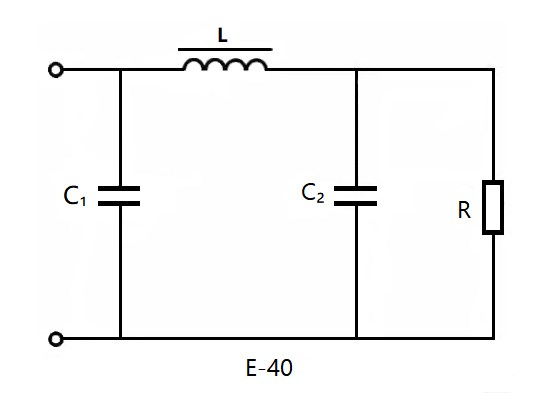
Figure 1. π-type filter circuit
The impeding effect of the inductor on AC is called inductive reactance, and it is related to both the frequency of the AC and the inductance value. The higher the AC frequency and the greater the inductance, the greater the inductive reactance. Taking advantage of this characteristic, inductors are frequently used in power supply filtering. The figure above shows a π-type filter circuit composed of capacitors and an inductor. Even after capacitor filtering, there may be some small fluctuations (ripple) in the DC signal. However, the inductor can oppose changes in current, effectively suppressing these small fluctuations and outputting purer DC power.
Beyond the blocking and filtering effects described above, inductors also serve important functions in suppressing electromagnetic interference (EMI), filtering signals, stabilizing current, reducing noise, energy storage in switching regulators, impedance matching in RF circuits, and tuning in resonant circuits.
Ⅳ How Do Inductors Work?

Figure 2. The simple structure of an inductor
In circuit diagrams, the inductor is represented by the following symbols:

Figure 3. Inductor symbols
When current flows through a wire, a concentric magnetic field is generated around the wire. If the wire is bent into a "spring shape" (helix) as shown in the figure, the magnetic flux inside the inductor points in the same direction, thereby strengthening the magnetic field. By adjusting the number of turns, a magnetic field proportional to the number of turns can be generated. This is the fundamental principle of the inductor.

Figure 4. Principle of inductor operation
A magnetic field is generated when current passes through an inductor; conversely, changes in the magnetic field produce a current (Faraday's Law of Electromagnetic Induction).
E = L × (di/dt)
Where:
L: Self-inductance of the inductor (in Henries)
E: Back electromotive force (EMF) (in Volts)
di/dt: Rate of change of current with respect to time (in Amperes per second)
The back electromotive force E generated in the inductor is proportional to the rate of change of current per unit time (di/dt). Therefore, it does not occur when a constant current flows in one direction (DC). In other words, the inductor has no impedance effect on steady DC current but opposes changes in AC current. Using this property, an inductor functions as an impedance element in AC circuits. The impedance Z (in Ohms, Ω) of an inductor is:
Z = ωL = 2πfL
Where f is the AC frequency (in Hertz) and L is the self-inductance of the inductor (in Henries).
An inductor is a passive electronic component that stores electrical energy in the form of magnetic flux. Typically, wire is wound into a coil; when current passes through, a magnetic field is generated according to the right-hand rule.
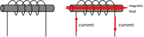
Figure 5. Inductor magnetic field generation
The calculation formula for the inductance value is shown below. The greater the number of turns, the stronger the magnetic field. Simultaneously, increasing the cross-sectional area or using a high-permeability magnetic core can enhance the magnetic field strength.
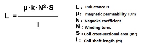
Figure 6. The calculation formula of the inductance value
Now let's examine what happens to the inductor when alternating current flows through it. Alternating current refers to current whose magnitude and direction change periodically with time. When AC passes through the inductor, the magnetic field generated by the current cuts through the other windings, thus generating a reverse voltage that opposes the current change. Particularly when the current suddenly increases, an electromotive force in the direction opposite to the current (i.e., in the direction of decreasing current) is generated to impede the increase of current. Conversely, when the current decreases, an EMF is generated in the direction of increasing current.
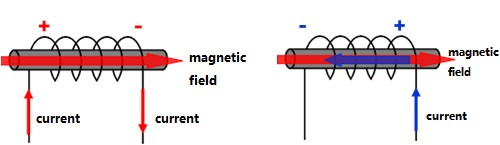
Figure 7. AC current flows through the inductor
If the direction of the current reverses, a reverse voltage is also generated. Before the current is significantly impeded by the reverse voltage, the current flow direction reverses again, preventing substantial current flow. On the other hand, direct current does not change in magnitude or direction, so there is no reverse voltage generated, and there is no risk of current interruption. In other words, an inductor is a component that allows direct current to pass relatively freely but impedes alternating current.
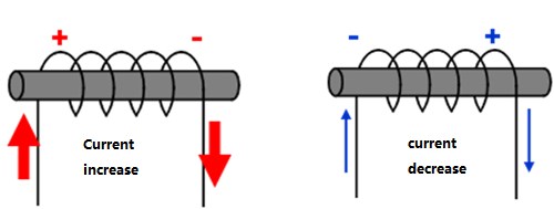
Figure 8. Reverse current flows through the inductor
The following figure will help you understand how the inductor works in a practical circuit:
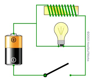
Figure 9. Inductor operation in a circuit
What you see here is a battery, a light bulb, a coil wound around an iron core (yellow), and a switch. The coil is the inductor. If you have read about the working principle of electromagnets, you will recognize that the inductor functions as an electromagnet.
If you remove the inductor from the circuit, you will have an ordinary flashlight circuit. Close the switch and the bulb will illuminate. However, with the inductor installed in the circuit as shown, its behavior is completely different.
The light bulb acts as a resistor (resistance generates heat, causing the filament in the light bulb to glow). The resistance of the wire in the coil is much lower (it is just wire), so when you turn on the switch initially, you might expect most current to flow through the low-resistance path of the inductor. What actually happens is that when you close the switch, the light bulb initially glows brightly and then dims. When you open the switch, the light bulb becomes very bright momentarily and then quickly goes out.
It is the inductor that causes this interesting phenomenon. When current begins to flow through the coil for the first time, the coil generates a magnetic field. During the formation of the magnetic field, the coil opposes the flow of current (due to Lenz's Law). Once the magnetic field is fully established, current can flow normally through the wire. When the switch is opened, the collapsing magnetic field around the coil induces a current in the coil until the magnetic field completely dissipates. This induced current can keep the bulb glowing for a brief period even after the switch is opened. In other words, an inductor stores energy in its magnetic field and opposes any change in the amount of current flowing through it.
Intuitive Understanding: The Water Wheel Analogy
An intuitive way to understand the working principle of an inductor is to imagine a narrow water pipe with water flowing through it, and a heavy water wheel with paddles immersed in the pipe. Imagine that the water in the pipe is initially stationary. Now you try to make the water flow. The water wheel will resist the flow of water until it accelerates to match the speed of the water. If you try to stop the flow of water in the pipe, the rotating water wheel will continue to move the water until the speed of the water wheel decreases to zero. The working principle of the inductor is analogous—the inductor opposes changes in electron flow through the wire.
Ⅴ Modern Applications and Recent Developments
As of 2025, the inductor industry has experienced significant growth and technological advancement. The global inductor market, valued at approximately $4.86-5.59 billion in 2024, is projected to reach $14-20 billion by 2030, driven by increasing demand in several key sectors.
Key Application Areas:
Automotive Electronics: The automotive power inductor market has seen explosive growth, particularly with the rise of electric vehicles (EVs). Power inductors are critical components in EV battery management systems, DC-DC converters, and onboard charging systems. The automotive power inductor market is expected to grow from $1.29 billion in 2024 to $3.30 billion by 2030.
5G and Telecommunications: The rollout of 5G networks has created substantial demand for high-frequency inductors capable of operating efficiently at millimeter-wave frequencies. These inductors are essential in 5G base stations, smartphones, and IoT devices.
Renewable Energy Systems: Inductors play crucial roles in solar inverters, wind turbine power converters, and energy storage systems, helping to manage power conversion and filtering in renewable energy applications.
Consumer Electronics: Compact, high-efficiency inductors are increasingly important in smartphones, tablets, wearables, and wireless charging systems.
Industrial Automation: Power inductors are essential in motor drives, robotics, and industrial power supplies.
Recent Technological Developments:
Miniaturization: Manufacturers continue to develop smaller inductors with higher inductance values. In January 2024, TDK unveiled the KLZ2012-A series, featuring ultra-compact inductors specifically designed for automotive audio applications, demonstrating the industry trend toward size reduction without performance compromise.
Enhanced Materials: In 2025, Resonac developed a new magnetic molding compound for inductors with 1.4× higher bending strength compared to conventional products, improving mechanical reliability in demanding applications.
High-Temperature Performance: New core materials and construction techniques enable inductors to operate reliably at temperatures exceeding 150°C, essential for automotive under-hood applications.
Improved Efficiency: Advanced core materials with lower losses and optimized winding techniques have increased inductor efficiency, reducing heat generation and improving overall system performance.
Integrated Solutions: Manufacturers are developing integrated power modules combining inductors with other passive components, reducing board space and simplifying circuit design.
Market Trends:
The inductor market is experiencing a compound annual growth rate (CAGR) of approximately 4.45% from 2025 to 2030. Surface mount device (SMD) inductors dominate the market due to their compatibility with automated assembly processes and compact form factors. The shift toward higher power density in power electronics continues to drive innovation in inductor design and materials.
⚠️ Important Considerations for Modern Designs
When selecting inductors for contemporary applications, engineers must consider not only traditional parameters like inductance value, current rating, and DC resistance, but also factors such as electromagnetic compatibility (EMC), thermal performance, mechanical stress resistance, and long-term reliability under varying environmental conditions. The increasing power density in modern electronics demands careful attention to thermal management and saturation characteristics.
📚 Recommended Articles:
📝 Article Update Information
Original Publication Date: 2020
Last Updated: October 2025
Update Summary:
Corrected technical terminology and improved clarity throughout the article
Added new section on modern applications and recent developments (2024-2025)
Updated market data and industry trends reflecting current state of inductor technology
Included recent product developments from major manufacturers (TDK, Resonac)
Enhanced explanations of electromagnetic principles with improved accuracy
Added information on emerging applications in EVs, 5G, and renewable energy
Improved formatting and visual presentation with enhanced inline styling
Corrected minor spelling and grammatical errors
Added practical considerations for modern circuit design
This article has been reviewed and updated to ensure accuracy and relevance for readers in 2025. All technical information has been verified against current industry standards and recent developments in inductor technology.
 UTMEL
UTMEL
We are the professional distributor of electronic components, providing a large variety of products to save you a lot of time, effort, and cost with our efficient self-customized service. careful order preparation fast delivery service
1.What is the function of an inductor?
An inductor has the functions of developing electromotive force in the direction that reduces fluctuation when a fluctuating current flows and storing electric energy as magnetic energy.
2.How does an inductor store energy?
Inductors Store Energy. The magnetic field that surrounds an inductor stores energy as current flows through the field. ... An alternating current (AC) flowing through the inductor results in the constant storing and delivering of energy.
3.How does inductor work in AC circuit?
An Inductor is usually a coil of wire that sets up an alternating magnetic field around it when an alternating current flows through it. Inductance is the property of an inductor that opposes the change in current.
4.What is inductor in simple words?
An inductor, also called a coil, choke, or reactor is a passive two-terminal electrical component that stores energy in a magnetic field when electric current flows through it. An inductor typically consists of an insulated wire wound into a coil around a core.
5.Does an inductor increase voltage?
Similarly, if the current through the inductor decreases, the magnetic field strength decreases, and the energy in the magnetic field decreases. This energy is returned to the circuit in the form of an increase in the electrical potential energy of the moving charges, causing a voltage rise across the windings.
 What is a Fixed Inductor?UTMEL15 April 202113203
Fixed inductors are a classification of inductors according to their structure, and fixed inductors are commonly used inductive devices. An inductor with a fixed inductance is called a fixed inductor (or a fixed coil), and it can be a coil with a single layer, multiple layers, honeycomb type, or a magnetic core. These coils are winded on the magnetic core using a wire of corresponded diameter and they are packaged with epoxy resin or plastic according to the inductance and the maximum DC operating current.
Read More Introduction to Inductive ReactanceUTMEL16 April 202114624
Alternating current can also pass through the coil, but the inductance of the coil has an obstructive effect on the alternating current. This obstruction is called inductive reactance.
Read More Inductance Basis: Definition, Structure and ApplicationsUTMEL18 April 20229577
Hello everyone, I am Rose. Today I will introduce inductance to you. Inductance is a property of a closed loop and a physical quantity. It is a circuit parameter that describes the induced electromotive force effect in this coil or in another coil due to changes in coil current. Inductance is a general term for self-inductance and mutual inductance. A device that provides an inductance is called an inductor.
Read More What is Color Ring Inductor? How to Read Inductor Color Code?UTMEL01 April 202516049
Hello everyone, I am Rose. Today I will introduce color ring inductor to you. A color ring inductor, also known as a color code inductor or a color ring inductor, is a self-inducting component. Together with a capacitor, the inductance coil (color ring inductance) frequently creates a resonant and filter circuit in the circuit.
Read More What is inductor: Symbol, Applications and TypesUTMEL04 January 202210833
As we begin our studies in 2022, we will work together to decode inductance today. What is an inductor? What enables it to work normally? The answer is the existence of this induced current.
Read More
Subscribe to Utmel !
![BR25G512FJ-3GE2]() BR25G512FJ-3GE2
BR25G512FJ-3GE2ROHM Semiconductor
![AT24C08C-XHM-T]() AT24C08C-XHM-T
AT24C08C-XHM-TMicrochip Technology
![M24C64-WMN6TP]() M24C64-WMN6TP
M24C64-WMN6TPSTMicroelectronics
![M93C46-WMN6TP]() M93C46-WMN6TP
M93C46-WMN6TPSTMicroelectronics
![ADAU1761BCPZ-R7]() ADAU1761BCPZ-R7
ADAU1761BCPZ-R7Analog Devices Inc.
![M24512-WMN6TP]() M24512-WMN6TP
M24512-WMN6TPSTMicroelectronics
![AT24C04C-SSHM-T]() AT24C04C-SSHM-T
AT24C04C-SSHM-TMicrochip Technology
![AT24C512C-SSHD-T]() AT24C512C-SSHD-T
AT24C512C-SSHD-TMicrochip Technology
![AT24C16C-SSHM-T]() AT24C16C-SSHM-T
AT24C16C-SSHM-TMicrochip Technology
![TPS61040DBVR]() TPS61040DBVR
TPS61040DBVRTexas Instruments


