
 Product
 Brand
Brand Articles
 Tools
Tools
What is Regulated Power Supply?

Regulated Power Supply
Catalog
Ⅰ Development History
In 1955, American scientist G.H. Royer first successfully developed a transistor DC converter that uses the saturation of the magnetic core for self-oscillation. Various forms of DC converters using this technology continue to emerge, thus replacing the early adopted rotating and mechanical vibrator display commutation equipment with a short life, poor reliability, and low conversion efficiency. Since the power transistor in the transistor-to-DC converter works in the on-off state, the regulated power supply produced therefrom has a large number of output groups, variable polarity, high efficiency, small size, and lightweight, so it was widely used in Aerospace and military electronic equipment. Because the microelectronic equipment and technology at that time were very backward, it was impossible to make transistors with high voltage resistance, high switching speed, and high power. Therefore, the DC converter of this period could only use low voltage input, and the conversion speed was not too high.
Beginning in the 1960s, due to the rapid development of microelectronics technology, transistors with high back voltage appeared. From then on, the DC converter can be directly inputted from the mains after rectification and filtering, and the power frequency transformer is no longer required to step down, thus greatly expanded its scope of application. On this basis, a switching power supply without a power frequency step-down transformer was born. Without the power frequency transformer, the volume and weight of the switching power supply are greatly reduced, and the switching power supply is truly efficient, small, and light.
After the 1970s, high-frequency, high-back-voltage power transistors, high-frequency capacitors, switching diodes, and the iron core of switching transformers related to this technology have also been continuously developed and produced. Therefore, the switching regulated power supply is widely used in the fields of electronic computers, communications, aerospace, color TV, etc.
Ⅱ The necessity of using regulated power supply
With the rapid advancement of society, electrical equipment is increasing day by day. However, the aging and lagging development of power transmission and distribution facilities, as well as poor design and insufficient power supply have caused the too low or high voltages. For electrical equipment, especially high-tech and precision equipment with strict voltage requirements, there is great risk insurance. Unstable voltage can cause fatal injury or malfunction to the equipment, affect production, cause delays in delivery, and unstable quality. At the same time, it accelerates the aging of the equipment, affects the service life and even burns the parts.
Ⅲ Main function
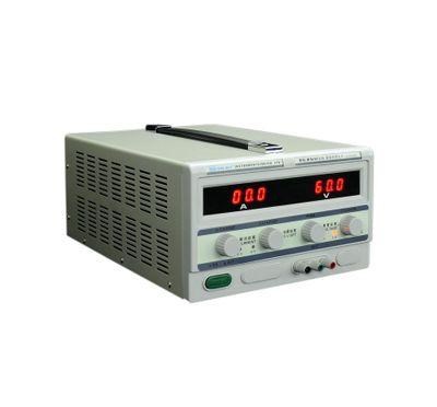
Regulated power supply
Stable voltage: When the grid voltage or load fluctuates momentarily, the regulated power supply will compensate the voltage amplitude with a response speed of 10-30ms to stabilize it within ±2%.
Multifunctional comprehensive protection: In addition to the most basic voltage stabilization function, the regulated power supply should also have over-voltage protection (more than +10% of the output voltage), under-voltage protection (below -10% of the output voltage), phase loss protection, short circuit, and overload protection.
Spike suppression: The power grid sometimes has a sharp pulse with a high amplitude and a narrow pulse width, which will break down electronic components with lower withstand voltage. The anti-surge components of the regulated power supply can effectively suppress such spikes.
Lightning protection: regulated power supplies have the lightning protection ability.
Ⅳ Working principle
The power frequency AC power becomes a stable DC power after the transformer is stepped down, rectified, and filtered. The rest of the figure is the control part for voltage regulation and stabilization. After the power supply is connected to the load, the output voltage is obtained through the sampling circuit, and the output voltage is compared with the reference voltage. If the output voltage is less than the reference voltage, the error value is amplified by the amplifying circuit and sent to the input of the regulator. The output voltage is adjusted by the regulator until it is equal to the reference value; if the output voltage is greater than the reference voltage, it is passed through the regulator Reduce the output.
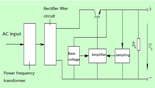
Working principle diagram of regulated power supply
The voltage regulator circuit is composed of a power supply circuit, a voltage detection control circuit, and an overvoltage protection circuit, as shown in the figure. The power circuit is composed of W4 and W5 windings of the voltage regulating transformer T, rectifier diodes VDl-VD4, and filter capacitors Cl and C2. The voltage detection control circuit is composed of resistor R-R7, potentiometer RPl, Rm, Zener diode VS, capacitor C3, C4 and operational amplifier integrated circuit IC (Nl-N3). The overvoltage protection circuit is made up of N3, transistor V3, resistor Rl2 and relay K inside the IC. Automatic voltage regulation circuit consists of resistors R8-Rll, transistors Vl, V2, DC motor M, sliding contacts and T windings Wl-W3. After connecting the output terminal of the AC voltage stabilizer to the mains, induced voltages are generated on the windings of W4 and W5 of T.
After this voltage is rectified by VDl-VD4 and filtered by Cl and C2, it provides an unstable working voltage of ±12V for IC and Vl, V2, etc. The +l2V voltage has other effects. After Rl-R3 voltage division and VS voltage stabilization, they respectively provide reference voltages for the inverting input terminals of Nl-N3; provide operating power for K and V3 of the overvoltage protection circuit; after R4, RP2, and R6 are divided, provide the detection voltage for the non-inverting input terminals of Nl and N2; after being divided by R7, RPl and R5, provide the detection voltage for the non-inverting input terminal of N3.
Nl-N3 compares the detection voltage of the positive-phase output large-end with the reference voltage of the reverse-phase output large-end, and uses the generated error voltage to control the automatic voltage regulator circuit.
When the mains voltage is normal, the output terminal voltages of N1 and N2 are OV, V1 and V2 are both in the cut-off state, and the motor M does not work.
When the mains voltage is low, Nl and N2 output a low level, turning on V2, turning off Vl, and rotating M counterclockwise, driving the sliding contact through the sliding wall arm to move, and contacting the corresponding voltage tap of T (Wl of T , W2 winding has a total of 21 voltage taps, and the voltage adjustment range of each gear is 5V), and the output voltage is increased through the W2 winding of T. When the output AC voltage rises to 220V, V2 ends and M stops. When the mains voltage is high, both Nl and N2 output high levels, turning on Vl, turning off V2, and turning M clockwise. The sliding arm drives the sliding contact to move and contacts the corresponding voltage tap of T. Wl winding to reduce the output voltage. When the output AC voltage drops to 220V, Vl ends and M stops. When the mains voltage is higher than 260V, N3 outputs a low level because the voltage at the non-inverting input terminal is higher than the voltage at the inverting input terminal, so that V3 is cut off, K is released, and its normally closed contact turns on the AC voltage output circuit. When the mains voltage is 160-260V, N3 outputs a high level because the voltage of the positive input terminal is lower than the voltage of the reverse input terminal, so that V3 is turned on, K is closed, and its normally closed contact is disconnected to ensure the load (Electrical appliances) will not be damaged by overvoltage.
Ⅴ Features
1.Advantage
1) Low power consumption and high efficiency. In the switching regulated power supply circuit, under the excitation of the excitation signal, the transistor V works alternately in the on-off and off-on switching states, the conversion speed is very fast, and the frequency is generally about 50kHz. In some technologically advanced countries, it can be several hundred or nearly 1000kHz. This makes the power consumption of the switching transistor V very small, and the efficiency of the power supply can be greatly improved, and its efficiency can reach 80%.
2) Small size and lightweight. There is no bulky industrial frequency transformer. After the power dissipation on the regulator tube V is greatly reduced, a larger heat sink is omitted. Due to these two reasons, the switching power supply is small in size and light in weight.
3) Wide voltage regulation range. The output voltage from the switching regulated power supply is adjusted by the duty cycle of the excitation signal, and the change of the input signal voltage can be compensated by frequency modulation or width modulation. In this way, it can still be used when the power frequency grid voltage changes greatly. Therefore, the voltage regulation range of the switching power supply is very wide, and the voltage regulation effect is very good. In addition, there are two methods for changing the duty cycle: pulse width modulation and frequency modulation. In this way, the switching regulated power supply not only has the advantage of a wide range of voltage stabilization but also has many ways to achieve voltage stabilization. The designer can flexibly choose various types of switching stabilized power supplies according to the requirements of actual applications.
4) The efficiency of filtering is greatly improved so that the capacity and volume of the filtering capacitor are greatly reduced. The operating frequency of the switching regulated power supply is basically at 50kHz, which is 1000 times that of the linear regulated power supply, which increases the filtering efficiency after rectification by almost 1000 times. The efficiency is increased by 500b times by adding capacitor filtering after half-wave rectification. Under the same ripple output voltage, when the switching regulated power supply is adopted, the capacity of the filter capacitor is only 1/500-1/1000 of the filter capacitor in the linear regulated power supply.
5) Flexible circuit forms. For example, there are self-excited and separately excited, wide-modulated and frequency-modulated, single-ended and double-ended types, etc. Designers can use the advantages of various types of circuits to design switches that can meet different applications of Power Supply.
2.Disadvantage
The disadvantage of switching regulated power supply is that there is more serious switching interference. In the switching regulated power supply, the power adjustment switching transistor V works in the switching state, and the AC voltage and current generated by it pass through other components in the circuit to produce spike interference and resonance interference. If these interferences are not taken certain measures to suppress, eliminate, they will seriously affect the normal operation of the whole machine. In addition, since the switching regulated power supply oscillator is not isolated from a power frequency transformer, these interferences will be connected to the power frequency grid, causing serious interference to other electronic instruments, equipment, and household appliances nearby.
 UTMEL
UTMEL
We are the professional distributor of electronic components, providing a large variety of products to save you a lot of time, effort, and cost with our efficient self-customized service. careful order preparation fast delivery service
1.What does regulated power supply mean?
Regulated power supplies have voltage regulators on their output. This works as long as the device is not drawing more than the rated output current of the power supply. Infancy electrical terms, a regulated power supply provides a constant output voltage, independent of the output current.
2.How do I know if my power supply is regulated?
You can generally stick one probe into the middle of the connector, and hold the other against the outside. With a few exceptions, the middle is positive, so use the red lead there, and use the black lead on the outside shell. Regulated supplies, without any load, should measure very close to the target voltage of 12v.
3.What is a Zener-regulated power supply?
The Zener voltage regulator consists of a current limiting resistor RS connected in series with the input voltage VS with the Zener diode connected in parallel with the load RL in this reverse biased condition. The stabilized output voltage is always selected to be the same as the breakdown voltage VZ of the diode.
4.How do you make a regulated power supply?
General Design of a Regulated Power Supply General Block Diagram. The Input Transformer. The Rectifier Circuit. The Smoothing Capacitor/Filter. The Regulator. Step 1: The Selection of Regulator IC. Step 2: The Selection of Transformer. Step 3: The Selection of Diodes for Bridge.
5.What's the difference between regulated and unregulated power supply?
In short, regulated power supplies using a voltage regulator circuit, convert the AC main voltage into a clean, stable DC voltage without noise and variations. In contrast, an unregulated power supply provides a rippled-DC voltage by only rectifying the AC.
 LLC Converter with Planar Matrix Transformer for High-Current-High-Power ApplicationsSaumitra Jagdale15 March 20244925
The rise of data centres in recent years, driven by cloud computing and big data, has caused a significant increase in electricity consumption. In the United States alone, it exceeded 70 billion kWh by 2014, making up 1.8% of total national electricity usage.
Read More Norton's Theorem: Working Principle, Circuit Design, and Modern ApplicationsUTMEL27 May 2026518
Norton's theorem simplifies complex linear electrical networks into an equivalent circuit containing a single current source in parallel with a resistor. This article explains the essential five-step workflow for calculating Norton parameters, compares it to its dual, Thévenin's theorem, and explores modern applications in power distribution networks, electric vehicle battery management, and fault diagnosis.
Read More SiC and GaN in 2026:How SiC and GaN Power Devices are Redefining AI Data Centers and 800V EVsUTMEL16 June 20261255
As AI data centers and 800V EVs hit physical thermal limits, the power electronics industry is shifting toward wide-bandgap semiconductors like SiC and GaN. This article explores how these materials are deployed in hybrid topologies to redefine power distribution, detailing high-voltage direct current architectures, engineering challenges in gate driving, and strategic sourcing solutions to build highly efficient, reliable modern power systems.
Read More Enhancing Frequency Stability in Modern Distributed Power SystemsRakesh Kumar, Ph.D.21 September 20244340
The article discusses the importance of primary frequency regulation in maintaining grid stability. It also explores battery energy storage systems, virtual synchronous generators, and advanced control strategies to enhance frequency stability in power systems.
Read More The Impact of SMPS on LED Lighting and Diverse IndustriesUTMEL05 June 20252693
Switched-Mode Power Supplies (SMPS) enhance LED lighting and industries by improving energy efficiency, reliability, and sustainability across diverse applications.
Read More
Subscribe to Utmel !
![ALF1T24]() ALF1T24
ALF1T24Panasonic Electric Works
![ARS144H]() ARS144H
ARS144HPanasonic Electric Works
![2966142]() 2966142
2966142Phoenix Contact
![LY4F-DC24]() LY4F-DC24
LY4F-DC24Omron Automation and Safety
![HC4-H-DC12V]() HC4-H-DC12V
HC4-H-DC12VPanasonic Electric Works
![ADW1212HLW]() ADW1212HLW
ADW1212HLWPanasonic Electric Works
![G2R-2A-DC12]() G2R-2A-DC12
G2R-2A-DC12Omron Electronics Inc-EMC Div
![NC4EBD-P-DC12V]() NC4EBD-P-DC12V
NC4EBD-P-DC12VPanasonic Electric Works
![3RT25162AP00]() 3RT25162AP00
3RT25162AP00Siemens
![DK2A-5V]() DK2A-5V
DK2A-5VPanasonic Electric Works


