
 Product
 Brand
Brand Articles
 Tools
Tools
Operational Amplifier Basics: Working Principle and Amplifier Circuit

What is an operational amplifier?
Catalog
The difference between operational amplifier and amplifier circuit |
The principle of operational amplifier
An operational amplifier (op-amp) is a circuit unit named from a functional point of view, which can be realized by a discrete device or in a semiconductor chip. With the development of semiconductor technology, most operational amplifiers exist in the form of a single chip. There are many types of operational amplifiers, which are widely used in the electronics industry.
The operational amplifier (op-amp) has two input terminals: 'a' (inverting input, labeled '-') and 'b' (non-inverting input, labeled '+'), and an output terminal o. When the voltage U- is applied between the terminal a and the common terminal (the common terminal is the point where the voltage is zero, which is equivalent to the reference node in the circuit.), and its actual direction is higher than the common terminal from the terminal a, the actual direction of the output voltage U is from the common end to the o end, that is, the two directions are exactly opposite. When the input voltage U+ is applied between the b terminal and the common terminal, the actual directions of U and U+ are exactly the same relative to the common terminal. For the sake of distinction, terminal a and terminal b are marked with "-" and "+" respectively but do not mistake them for the positive and negative polarity of the voltage reference direction. The positive and negative polarity of the voltage should be marked separately or indicated by arrows. The inverting amplifier and non-inverting amplifier are as follows:
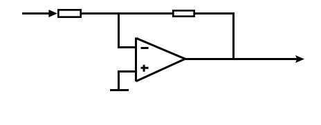
Figure 1. inverting amplifier
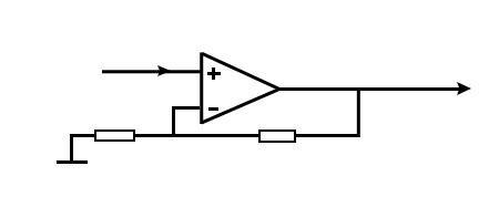
Figure 2. non-inverting amplifier
Generally, operational amplifiers can be simply regarded as a high-gain direct-coupled voltage amplifier unit with a signal output port (Out) and two high-impedance input terminals of in-phase and anti-phase. Therefore, operational amplifiers can be used to make in-phase, anti-phase, and differential amplifiers.
Op-amps operate in either dual-supply (±VCC) or single-supply configurations, with the output swing dependent on the supply type. For a dual power supply operational amplifier, its output can change on both sides of zero voltage, and the output can also be set to zero when the differential input voltage is zero. Using a single power supply operational amplifier, the output varies within a certain range between the power supply and the ground.
The input potential of the operational amplifier is usually required to be higher than a certain value of the negative power supply and lower than a certain value of the positive power supply. The specially designed operational amplifier can allow the input potential to vary from the negative power supply to the positive power supply, even slightly higher than the positive power supply or slightly lower than the negative power supply. This type of operational amplifier is called a rail-to-rail input operational amplifier.
The output signal of the operational amplifier is proportional to the voltage difference between the two input terminals. In the audio segment: output voltage = A0 (E1-E2), where A0 is the low-frequency open-loop gain of the operational amplifier (such as 100dB, which is 100000 times), E1 is the input signal voltage at the non-inverting terminal, and E2 is the input signal voltage at the inverting terminal. Note: Modern precision op-amps like the Texas Instruments OPA2197 offer gains up to 120 dB with rail-to-rail output.
Modern Op-Amp Types
1. CMOS Op-Amps for Low Power
Example: Microchip MCP6001
Features:
Low Power Consumption: Typically 100 µA quiescent current.
Rail-to-Rail Input and Output: Allows for maximum signal swing.
Supply Voltage Range: 1.8V to 6V.
Gain Bandwidth Product (GBWP): 1 MHz.
Packages: Available in compact SC-70 and SOT-23 packages.
Applications: Automotive, portable equipment, photodiode amplifiers, analog filters, notebooks, PDAs, and battery-powered systems12.
2. Precision Op-Amps with Low Offset
Example: Analog Devices AD8551
Features:
Zero-Drift Technology: Offers extremely low offset voltage (<1 µV) and drift.
Rail-to-Rail Input and Output: Suitable for high-side and low-side sensing.
Supply Voltage Range: 2.7V to 5V.
Temperature Range: -40°C to +125°C.
Low Noise: Ideal for precision applications.
Applications: Temperature, position, and pressure sensors, medical equipment, strain gage amplifiers, and automotive systems34.
3. High-Speed Op-Amps for RF Applications
Example: Texas Instruments THS3491
Features:
High Bandwidth: 900 MHz small signal bandwidth.
High Slew Rate: 8000 V/µs.
High Output Current: Up to 500 mA.
Low Distortion: Suitable for high-frequency applications.
Applications: High-voltage arbitrary waveform generators, LCD test pattern generators, LCR meter output drivers, power FET drivers, high-capacity piezoelectric drivers, VDSL line drivers5.
These modern op-amp variants are designed to meet specific needs in various fields, from low-power portable devices to high-speed RF applications.
*Utmel Electronics stocks 10,000+ op-amp variants from TI, STMicro, and ON Semiconductor, with same-day shipping and datasheet support.
Classic operational amplifier circuit diagram
Classic operational amplifier circuit diagram 1
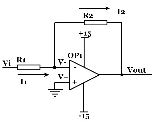
The non-directional terminal of the op amp in Figure 3 is grounded = 0V, the reverse terminal, and the non-directional terminal are virtual short circuits, so it is also 0V. The 'virtual short' principle assumes the inverting and non-inverting inputs are at the same potential due to high open-loop gain (not a physical short). The input resistance of the reverse input terminal is very high, and there is almost no current injection and outflow. Then R1 and R2 are in series, the current flowing through each component in a series circuit is the same, that is, the current flowing through R1 and the current flowing through R2 are the same.
The current flowing through R1 I1=(Vi-V-)/R1……a
The current flowing through R2 I2=(V--Vout)/R2……b
V-=V+=0……c
I1=I2……d
Solve the above algebraic equation is Vout=(-R2/R1)*Vi
This is the input and output relationship of the legendary inverting amplifier.
Classic operational amplifier circuit diagram 2

In Figure 4, Vi and V- are virtual short, then Vi=V……a
Because of virtual open, there is no current input and output at the reverse input terminal, and the currents through R1 and R2 are equal. Set this current as I. From Ohm's law: I=Vout/(R1+R2)……b
Vi is equal to the partial pressure on R2, namely: Vi=I*R2……c
c is obtained by the abc formula. Vout=Vi*(R1+R2)/R2
This is the formula of the legendary co-directional amplifier.
Classic operational amplifier circuit diagram 3

In Figure 5, we know from the virtual short circuit: V-=V+=0……a
a According to the virtual disconnection and Kirchhoff's law, the sum of the current through R2 and R1 is equal to the current through R3, so (V1–V-)/R1+(V2– V-)/R2=(Vout–V-)/R3……b
b is substituted into formula a, and formula b becomes V1/R1+V2/R2=Vout/R3.
If R1=R2=R3, the above formula becomes Vout =V1+V2, this is legendary adder.
Classic operational amplifier circuit diagram 4

In Figure 6, because of the virtual open circuit, no current flows through the op amp in the same direction, so the currents flowing through R1 and R2 are equal, and the currents flowing through R4 and R3 are also equal. So (V1–V+)/R1=(V+-V2)/R2……a
(Vout–V-)/R3=V-/R4……b
Knowing from the shortcoming: V+=V-……c
if R1= R2, R3=R4, then V+=(V1+V2)/2V-=Vout/2.
We can be derived from the above formula, so Vout=V1+V2 is also an adder.
Introduction to the amplifier circuit
The amplifying circuit is also called an amplifier. It is one of the most widely used electronic circuits and a basic unit circuit that constitutes other electronic circuits. The so-called amplification is to amplify the input weak signal (referred to as the signal, which refers to the changing voltage, current, etc.) to the required amplitude value and the signal consistent with the original input signal change law, that is, to perform undistorted amplification. It only makes sense to zoom in without distortion. The essence of the amplifying circuit is the control and conversion of energy. According to the common end of the input loop and the output loop, the amplifying circuit has three basic forms: common emitter amplifier circuit, common collector amplifier circuit, and common base amplifier circuit.
The actual amplifier circuit is usually composed of a signal source, an amplifier composed of a transistor, and a load.
Features of amplifier circuit:
1. There are two working states of static and dynamic, so sometimes it is often necessary to draw its DC path and AC path for analysis;
2. Circuits are often added with negative feedback. This kind of feedback is sometimes in this stage, sometimes from the latter stage to the previous stage, so when analyzing this stage, we should be able to "look forward and backward". After understanding the principle of each level, the entire circuit can be colluded for comprehensive synthesis.
Transistor amplifier circuit diagram:
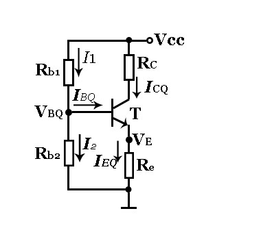
This is a typical transistor amplifier circuit. The direction of current flow and the role of each bias resistor can be seen from the above.
The difference between operational amplifier and amplifier circuit
The amplifying circuit only has the function of amplification. It is generally used for analog signal amplification of various detection devices. Of course, some analog amplifier circuits can also implement arithmetic logic functions. The output of the amplifying circuit is an analog quantity.
Operational amplifiers are generally integrated on a chip, and multiple operational amplifiers are integrated into a chip. Operational amplifiers output analog signals. Comparators (a related component) output digital signals based on input thresholds, which can be used for signal comparison and amplification. The operational amplifier has both positive and negative signal inlets. What signal is the input the positive signal terminal, then the same signal is the output. The negative signal input terminal is opposite, for example, the negative signal terminal inputs a positive signal, and the output terminal is opposite, which is a negative signal.
For example, a 36V electric vehicle uses four lights to display the power, and supplies 5V to the operational amplifier chip. (Modern electric vehicles (e.g., 48V systems) use op-amps in battery management systems (BMS) for voltage monitoring.) Make several fixed voltages, the voltages are 40, 38, 36, and 34 respectively. They are connected to the four negative input terminals of a chip with four operational amplifiers, and the four positive signal input terminals are connected to battery sampling. When the battery voltage is greater than 40V, then the operational amplifier outputs a high level, and the indicator light is on. When it is lower than 40V, the positive signal input terminal is lower than the negative signal input terminal, the output low level indicator does not light up. The other three groups of operational amplifiers are the same. With ordinary amplifier circuits, there will be no such situation that the signal voltage at the input end is higher than the output signal.
In addition, the input end of the operational amplifier is used as a signal ground and the other end is connected to the input signal. It can be used as an amplifier, such as a power amplifier front stage. The amplifier circuit can be understood as an operational amplifier.
The two circuits are firstly different in circuit principle. Some circuits both use transistors for amplification and operational amplifiers because the input signal voltage cannot directly work on the operational amplifier.
Reference
Analog Devices. (n.d.). Operational Amplifiers. Retrieved from https://www.analog.com/
Coughlin, R. F., & Driscoll, F. F. (2001). Operational Amplifiers and Linear Integrated Circuits. Prentice Hall.
Hassan, H. (n.d.). Fundamental and Applications of Operational Amplifiers. Retrieved from https://publisher.uthm.edu.my/omp/index.php/penerbituthm/catalog/download/447/933/1226?inline=1
Jung, W. (2005). Op-Amp Applications Handbook. Newnes.
Nisshinbo Microdevices. (n.d.). Operational Amplifier Basics. Retrieved from https://www.nisshinbo-microdevices.co.jp/en/design-support/basic-opamp/
 UTMEL
UTMEL
We are the professional distributor of electronic components, providing a large variety of products to save you a lot of time, effort, and cost with our efficient self-customized service. careful order preparation fast delivery service
1 Why is it called an operational amplifier?
Op-amp stands for operational amplifier. Originally, op-amps were so named because they were used to model the basic mathematical operations of addition, subtraction, integration, differentiation, etc. in electronic analog computers. In this sense, a true operational amplifier is an ideal circuit element.
2 Top 10 Op Amp Circuits
Voltage Follower Inverting Op Amp Non-inverting Op Amp Non-inverting Summing Amplifier Inverting Summing Amplifier Differential Amplifier Integrator Op Amp Differentiator Converter current – voltage Negative resistance
3 What is an ideal operational amplifier?
The ideal op amp is an amplifier with infinite input impedance, infinite open-loop gain, zero output impedance, infinite bandwidth, and zero noise. It has positive and negative inputs which allow circuits that use feedback to achieve a wide range of functions.
4 What is op amp’s application?
Op amps are used in a wide variety of applications in electronics. Some of the more common applications are: as a voltage follower, selective inversion circuit, a current-to-voltage converter, active rectifier, integrator, a whole wide variety of filters, and a voltage comparator.
5 What is CMRR in op amp?
The op amp common-mode rejection ratio (CMRR) is the ratio of the common-mode gain to differential-mode gain. For example, if a differential input change of Y volts produces a change of 1 V at the output, and a common-mode change of X volts produces a similar change of 1 V, then the CMRR is X/Y.
6 What is the principle of amplifier?
The power amplifier works on the basic principle of converting the DC power drawn from the power supply into an AC voltage signal delivered to the load. Although the amplification is high the efficiency of the conversion from the DC power supply input to the AC voltage signal output is usually poor.
7 How do I choose between single-supply and dual-supply op-amps?
Single-supply op-amps (e.g., LM358) suit 0-5V systems, while dual-supply (e.g., NE5532) excel in audio where negative voltages are needed.
8 How to reduce op-amp noise?
Use 1% tolerance resistors, bypass capacitors (0.1 µF), and low-noise op-amps like the LT1028.
 Introduction to MD8002A Audio AmplifierUTMEL27 March 20259385
The MD8002A is an audio power amplifier that uses a 5V DC power supply to provide 2.0 watts of continuous power to a BTL load with less than 10% distortion. It was created with the aim of providing high-quality o/p control with fewer components. It doesn't use any output coupling capacitors or bootstrap capacitors.
Read More") Understanding the Low Noise Amplifier (LNA)UTMEL20 March 202525936
Understanding the Low Noise Amplifier (LNA)UTMEL20 March 202525936A low noise amplifier is an amplifier with a very low noise figure. It is generally used as a high-frequency or intermediate-frequency preamplifier for various types of radio receivers, as well as amplifying circuits for high-sensitivity electronic detection equipment.
Read More Introduction to Optical AmplifierUTMEL27 March 202510064
An optical amplifier is a subsystem product that can amplify optical signals in optical fiber communication systems. The principle of the optical amplifier is basically based on the stimulated radiation of the laser, which realizes the amplification effect by converting the energy of the pump light into the energy of the signal light.
Read More What is an Inverting Amplifier?UTMEL25 April 202511919
An inverting amplifier is a fundamental configuration of operational amplifiers where the output signal has opposite polarity to the input signal. This configuration uses an operational amplifier with its inverting input terminal receiving the input signal, while the non-inverting terminal is typically connected to ground. The primary function of this circuit is to amplify the input signal while inverting its phase by 180 degrees.
Read More Low-Power Design of Operational AmplifiersUTMEL27 March 20257350
Hello, this is Candy. With the rise in popularity of battery-powered electronics in recent years, analog circuit designers have been increasingly concerned about power usage. This article will cover how to use low-power op amps in system design, as well as low-power op amps with low supply voltage capabilities and their applications, as well as how to read and understand op amp data sheets appropriately. Circuit design with energy-saving technologies for more efficient device choices.
Read More
Subscribe to Utmel !
![M5KP14AE3/TR]() M5KP14AE3/TR
M5KP14AE3/TRMicrochip Technology
![MART100KP85CA/TR]() MART100KP85CA/TR
MART100KP85CA/TRMicrochip Technology
![JANTX1N6461US/TR]() JANTX1N6461US/TR
JANTX1N6461US/TRMicrochip Technology
![ICT-10/TR]() ICT-10/TR
ICT-10/TRMicrochip Technology
![JANTX1N6137AUS/TR]() JANTX1N6137AUS/TR
JANTX1N6137AUS/TRMicrochip Technology
![JANTXV1N6157AUS/TR]() JANTXV1N6157AUS/TR
JANTXV1N6157AUS/TRMicrochip Technology
![JAN1N5650A]() JAN1N5650A
JAN1N5650AMicrochip Technology
![MPLAD130KP275CVE3/TR]() MPLAD130KP275CVE3/TR
MPLAD130KP275CVE3/TRMicrochip Technology
![0603L025YR]() 0603L025YR
0603L025YRLittelfuse Inc.
![JANTX1N5660A/TR]() JANTX1N5660A/TR
JANTX1N5660A/TRMicrochip Technology

