
 Product
 Brand
Brand Articles
 Tools
Tools
How does a Photodiode Work?
What is Photodiode?
Catalog
I Photodiode Parameters
A photodiode is a special diode (light-receiving device) that converts optical signals into electrical signals. Its symbol is shown in the figure.

FIG 1. Photodiode Symbol
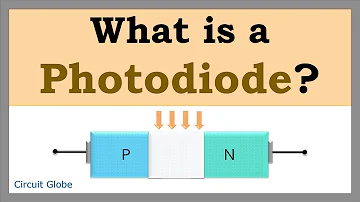
Similar to ordinary diodes, its basic structure is also a pn junction. Its shell has a window with glass for light penetration as shown below.

Figure 2. Photodiode Structure
The photodiode works in the reverse state and its reverse current increases with the increase of light intensity.
When there is no light, the reverse current is very small (generally less than 0.1μa), called the dark current. And the reverse resistance at this time is tens of mΩ.
When there is light, a reverse current is formed, called photocurrent. At this time, the reverse resistance of the photodiode drops to several kΩ.
1. Dark Current
In the photoconduction mode, when there is no light, the current through the photodiode is a dark current. Dark current in photodiode includes radiation current and saturation current of the semiconductor junction. It must be measured in advance. Especially in precision optical power measurement, the error caused by dark current must be carefully considered and corrected.
2. Photodiode Response Time
The response rate is the ratio of the photocurrent in the photoconduction mode to the emergency light, in A/W. The response characteristic can also be expressed as quantum efficiency of the photodiode, which is the ratio of the number of carriers generated by light to the number of emergency light photons.
3. Noise Equivalent Power(NEP)
Noise equivalent power refers to the minimum optical power required to generate photocurrent, which is equal to the RMS of noise power at 1 Hz. It is approximately equal to the minimum detectable input power of the photodiode.
A related property is detectivity (D), which is the inverse of the noise equivalent power.
4. Frequency Response Characteristic
It is mainly determined by three factors:
(1) The diffusion time of photogenerated carriers near the depletion layer;
(2) The drift time of photogenerated carriers in the depletion layer;
(3) The circuit time constant determined by the load resistance and the parallel capacitor.
II Photodiode Characteristics
1. Volt-ampere Characteristics
It refers to the relationship between the photocurrent on the photodiode and the voltage applied across it.

Figure 3. Photodiode Volt-ampere Characteristics
2. Illumination Characteristics
It refers to the relationship between luminous flux and photocurrent when the photodiode voltage between the cathode and anode is constant. The slope of the light characteristic curve is called the photodiode sensitivity.
3. Spectral Characteristics
The relationship between the photocurrent and the incident light wavelength is called the spectral characteristic.
The photon energy is related to the light wavelength: the longer the wavelength, the smaller the photon energy; the shorter the wavelength, the greater the photon energy.
III Photodiode Types
1. PN Photodiode
Features: small dark current and low response speed
Uses: illuminometer, color photodiode sensor, phototransistor, linear image photodiode sensor, spectrophotometer, camera exposure meter.
2. PIN Photodiode
Features: It's a kind of large dark current photodiode, with low junction capacity and fast response
Uses: high-speed light photodiode detector, optical communication, optical fiber, remote control, photoelectric transistor, fax.
3. Launch Key Photodiode
Features: Use Au film and N-type semiconductor junction instead of P-type semiconductor
Uses: detection of short-wave light as ultraviolet rays
4. Avalanche Photodiode
Features: It's a kind of weak light photodiode detector with a fast response speed
Uses: High-speed optical communication, high-speed optical detection
IV How Does a Photodiode Work?
Photodiode works according to the following principle:
When there is light, the photon with energy enters the PN junction and transfers the energy to the electrons on the covalent bond. Some electrons break away from the covalent bond, and electron-hole pairs are produced, also called photo-generated carriers.
The number of photo-generated carriers is limited, and the number of majority carriers before light is much greater than that of photo-generated carriers. Therefore, the photo-generated carrier has a small effect on the number of carriers, but the number of minority carriers has a large impact. This is why the photodiode works under reverse voltage instead of forward voltage.
So, under reverse voltage, the minority carriers increased by the photogenerated carriers participate in the drifting motion. In the P region, the photogenerated electrons diffuse to the PN junction. If the P region thickness is less than the electron diffusion length, then most photogenerated electrons will pass through the P region to the PN junction. This is the same in the N region.

Figure 4. Photodiode Working Principle
Therefore, in photodiode manufacture, the PN junction is very shallow to promote the drift of minority carriers.
Generally speaking, the work of a photodiode is an absorption process, which converts the light change into a reverse current change. The combination of the current and the dark current is the photocurrent, so the dark current is minimized as much as possible to improve the photodiode sensitivity to light.
The light intensity is proportional to the photocurrent. The greater the light intensity, the greater the reverse current. This characteristic is called photoconductivity, and the current caused by it is called photocurrent.
V Function of Photodiode
Photodiodes are widely used for:
1. Light Control
The photodiode can be used as a photoswitch, and its circuit is shown in the figure below. When there is no light, the photodiode VD1 is cut off due to the reverse voltage. The transistor VT1 and VT2 are also cut off due to no base current. The relay is in the released state.
When light is emitted on VD1, it transits from cut-off to conduction. So, VT1 and VT2 are turned on successively, and the relay K pulls in to connect the control circuit.
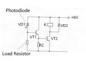
Figure 5. Photodiode for Light Control
2. Light Signal Reception
Photodiodes can be used to receive light signals. The figure below shows the light signal receiving and amplifying photodiode circuit. The light signal is received by the photodiode VD, amplified by VT, and output through the coupling capacitor C.

Figure 6. Photodiode for Light Signal Reception
VI Photodiode Applications
Specific photodiode application is:
1. Photocell
The photocell is essentially a large-area PN junction. When light is emitted on one PN junction surface, such as the P region surface, if the photon energy is greater than the forbidden bandwidth of the semiconductor material, each photon in the P region will produce a free electron-hole pair.
Figure 7. Photocell
Electron-hole pairs diffuse rapidly inward, and, and an electromotive force related to the light intensity is formed under the junction electric field.
At this time, if we use it as a power source and connect it to an external circuit, it will continuously supply power as long as there is light, which is the photocell. In other words, a photocell is a PN junction photoelectric device without a bias voltage. It and can directly convert light energy into electrical energy.
According to the purpose of the photocell, it can be divided into solar photocells and measuring photocells.
Difference between photodiodes and photocells
Photocell: used for energy conversion. Advantage: increase the conversion rate.
Photodiode: used for detection. Advantages: high sensitivity, fast response, and high quantum efficiency.
They're different in:
| Bias Method | Doping Density(cm) | Resistivity(Ω/cm) | Light Area |
Photocell | Photocell Null Bias | 1016-1019 | 0.1-0.01 | Large |
Photodiode | Photodiode Reverse Bias | 1012-1013 | 1000 | Small |
2. Solar Cell
A solar cell is a semiconductor device, as shown in the Figure below. When sunlight is emitted on the semiconductor, part of it is reflected, and the rest is absorbed or penetrates the semiconductor.
Some absorbed light turns into heat, while other photons collide with the valence electrons making up the semiconductor, thus generating electron-hole pairs. In this way, light energy is converted into electrical energy.
Therefore, after the sunlight, a DC voltage will be generated at both ends of the solar cell, thereby directly converting sunlight energy into a DC current. If we weld metal leads to the P layer and the N layer, and connect the load, the current will flow through the external circuit.
In this way, if we connect the photocells in series and parallel, a certain voltage and current can be generated, thus outputting power.

Figure 8. Solar Cell
3. Photovoltaic Power Generation Lighting System
The photovoltaic power generation system is a power generation system that uses solar cells to convert solar energy into electrical energy. It uses the photovoltaic effect.
The main components are solar cells, storage batteries, controllers, and inverters. It has high reliability, long service life, no pollution, independent power generation, and grid-connected photodiode operation.
Because the photodiode photovoltaic mode is greatly affected by external environmental factors such as light and temperature, the operating point changes rapidly.
There are independent power generation systems and grid-connected power generation systems.
(1) Independent photovoltaic power generation system
An Independent photovoltaic power generation system is a power generation method not connected to the power grid. It needs batteries to store energy for the night. Independent solar photovoltaic power generation is mainly used in remote villages and homes
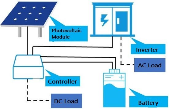
Figure 9. Structure Diagram of Photovoltaic Power Generation System
(2) Grid-connected photovoltaic power generation system
The grid-connected photovoltaic power generation system is connected to the national grid to supply the power grid. It does not need batteries. The residential photovoltaic power generation system is mostly in households. They are also used for public facilities, lighting systems in night landscaping, and solar farms.
VII Detection Method
1. Resistance Measurement Method
Use the "1k" of a multimeter to test the photodiode. The forward resistance of the photodiode is about 10KΩ.
When there's no light, if the measured reverse resistance is ∞, the diode is good, or there is a large leakage current.
When there is light, the reverse resistance decreases with the increase of light intensity. If the resistance can reach a few kΩ; or below 1kΩ, the diode is good; if the reverse resistance is ∞ or zero, the diode is broken.
2.Voltage Measurement Method
Use the "1V" gear of a multimeter. Connect the red test lead to the positive pole of the photodiode, and the black test lead to the negative pole. Under the light, the voltage is proportional to the light intensity, generally up to 0.2V-0.4V.
3.Short-circuit Current Measurement Method
Use the "50μA" gear of multimeter. Connect the red test lead to the photodiode positive pole, and the black test lead to the negative pole. Under incandescent lamps (not fluorescent lamps), if the short-circuit current increases with the light increases, the diode is good. The short-circuit current can reach tens to hundreds of μA.
Sometimes, it is necessary to distinguish between infrared light-emitting diodes and infrared photodiodes.
If they are both packed with transparent resin, we can see their die installation. There is a shallow plate under the infrared LED die, but there is no photodiode die.

Figure 10. Infrared Photodiode
if it's a small photodiode or it's packed with black resin, you can use a multimeter (set at 1k gear) to measure resistance.
First, make sure the diode is not exposed to light. If the measured forward resistance is 20-40kΩ, and the reverse resistance is greater than 200kΩ, the forward resistance is about 10k and the reverse resistance is close to ∞, it is the photodiode.
Recommended Articles:
 UTMEL
UTMEL
We are the professional distributor of electronic components, providing a large variety of products to save you a lot of time, effort, and cost with our efficient self-customized service. careful order preparation fast delivery service
1.What is photodiode explain its working principle?
The working principle of a photodiode is, when a photon of ample energy strikes the diode, it makes a couple of electron-hole. Therefore, holes in the region move toward the anode, and electrons move toward the cathode, and a photocurrent will be generated.
2.Why photodiodes are reverse biased?
The photodiode is reverse biased for operating in the photoconductive mode. As the photodiode is in reverse bias the width of the depletion layer increases. This reduces the junction capacitance and thereby the response time. In effect, the reverse bias causes faster response times for the photodiode.
3.What is photodiode most commonly used?
Photodiodes are used in consumer electronics devices such as compact disc players, smoke detectors, medical devices and the receivers for infrared remote control devices used to control equipment from televisions to air conditioners.
4.Is silicon used in photodiode?
Because of their small size, low noise, high speed and good spectral response, silicon photodiodes are being used for both civilian and defense related applications. ... Photodiode – operational amplifier combinations used for the detection of very low light intensities will be introduced.
5.What is photodiode and its application?
A photodiode is a semiconductor p-n junction device that converts light into an electrical current. The current is generated when photons are absorbed in the photodiode. Photodiodes may contain optical filters, built-in lenses, and may have large or small surface areas.
 All You Need to Know About Rectifier CircuitUTMEL24 April 202517548
All You Need to Know About Rectifier Circuit
Read More 15 Key Elements of Diode SelectionUTMEL26 November 202118860
Hello everyone, I am Rose. Welcome back to the new post today. Diodes are one of the most common components in our circuit boards. So, what factors should be considered when selecting models?
Read More What is a PIN Diode?UTMEL04 February 202110149
While diodes with a simple PN junction are by far the most common type of diode in operation, in a variety of applications, other forms of diode may be used. The PIN diode is one type that is used for a number of circuits. In a variety of places, this diode type is used. For RF switching, the PIN diode is very fine, and the PIN structure in photodiodes is very useful as well.
Read More Microwave Diode: Introduction and TypesUTMEL07 January 202125948
Microwave diodes are diodes that work in the microwave frequency band. It is a solid-state microwave device. Microwave band usually refers to the frequency from 300 MHz to 3000 GHz. After the discovery of the point contact diode effect at the end of the 19th century, microwave diodes such as PIN diodes, varactor diodes, and Schottky diode tubes appeared one after another. Microwave diodes have the advantages of small size and high reliability, and are used in microwave oscillation, amplification, frequency conversion, switching, phase shifting and modulation.
Read More What Determines the Maximum Operating Frequency of a Diode?UTMEL29 June 202212885
Hello, wish you a wonderful day. In this essay, we first pose the following query: what determines the diode's maximum operating frequency? In regards to the solution, the first thing we need to understand is that the junction capacitance and the reverse recovery time of the diode are two distinct concepts. The charging and discharging times of the junction capacitance cannot match the reverse recovery time. You say that, why? Let's start by taking a look at these facts.
Read More
Subscribe to Utmel !
![BLM21PG221SH1D]() BLM21PG221SH1D
BLM21PG221SH1DMurata Electronics
![BLM21BD272SN1L]() BLM21BD272SN1L
BLM21BD272SN1LMurata Electronics
![BLM18AG331SN1D]() BLM18AG331SN1D
BLM18AG331SN1DMurata Electronics
![BLM21BB050SN1D]() BLM21BB050SN1D
BLM21BB050SN1DMurata Electronics
![BLM15AX100SN1D]() BLM15AX100SN1D
BLM15AX100SN1DMurata Electronics
![BLM15HD102SH1D]() BLM15HD102SH1D
BLM15HD102SH1DMurata Electronics
![MMZ1608B121CTAH0]() MMZ1608B121CTAH0
MMZ1608B121CTAH0TDK Corporation
![MMZ1608R102ATA00]() MMZ1608R102ATA00
MMZ1608R102ATA00TDK Corporation
![NFM41PC155B1H3L]() NFM41PC155B1H3L
NFM41PC155B1H3LMurata Electronics
![NFM3DCC223R1H3L]() NFM3DCC223R1H3L
NFM3DCC223R1H3LMurata Electronics


