
 Product
 Brand
Brand Articles
 Tools
Tools
Introduction to Coupling Capacitor
Catalog
I. Working Principle
A coupling capacitor is one of the capacitors, and its function can be simply understood as coupling. In fact, the coupling capacitor is also known as electrostatic coupling, which is a coupling method due to the existence of distributed capacitance. So what about the coupling capacitor principle? Let's take a look together.
The capacitor is connected to an AC circuit, and the voltage of the circuit connected to a pin gradually increases, and gradually accumulates charge on the plate where it is located. When the voltage of the circuit connected to the pin drops, the charge accumulated when the potential is high returns to the circuit. The same goes for the other end. The capacitor is insulated, and no current flows through the entire capacitor, but the phenomenon that it accumulates and releases charges as the potential rises and falls, which makes people mistakenly think that there is current passing.
Coupling refers to the process of signal transfer from the first stage to the second stage. Capacitors are often used in the coupling of AC signals because they can cut off DC and prevent DC signals from passing, and the DC biases between the various levels are irrelevant. The "AC" characteristic of the capacitor allows the AC signal to flow through the capacitor to the next stage.
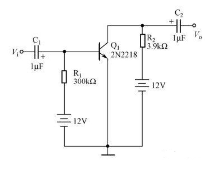
The coupling of the capacitor is based on the "traffic blocking" characteristic of the capacitor. The input frequency is 1kHz and the amplitude is 20mV sinusoidal signal in the picture; 2N2218 is a triode when the circuit provides suitable DC voltage to the 3 pins of the triode, it can be amplified The input sine signal.
Coupling capacitors make the two systems of strong and weak currents coupled and isolated by capacitors, provide high-frequency signal paths, prevent power frequency current from entering the weak current system, and ensure personal safety. In addition to the above functions, the coupling capacitor with voltage extraction device can also extract power frequency voltage for protection and reclosing use, and play the role of a voltage transformer. There are many coupling methods. The capacitor is connected to the AC circuit, and the voltage of the circuit connected to a pin gradually increases, and the charge is gradually accumulated on the plate where it is located. When the voltage of the circuit connected to the pin drops, the potential is increased. When the accumulated charge returns to the circuit.
In fact, as far as the principle of coupling capacitor is concerned, it can isolate the DC, and the AC signal is coupled in the form of increasing and decreasing the potential at both ends and transmitted to the following circuit components. The function is to cut off the current of the previous amplifier circuit so that the AC signal can pass normally.
II. Features
1. Construction
It is a parallel plate capacitor in general, and its construction is extremely simple. A dielectric material is used in between the parallel plates of this capacitor. So while getting final output like AC signals, this capacitor plays a key role.
Coupling capacitors are mainly used in analog circuits, while digital circuits use decoupling capacitors. The connection of this capacitor with the load for AC coupling can be done in series.
Low-frequency signals like DC are blocked by a capacitor and high-frequency signals like AC are allowed. It reacts to various frequencies in various ways. This capacitor's resistance or impedance is very high for low-frequency signals. Likewise, high-frequency signals, it has less resistance or impedance to easily pass through the circuit.
2. Calculation
A capacitor is short at high frequencies, whereas it is open at low frequencies. By using the following formula, the capacitance of this capacitor can be calculated.
Xc = 1/2πfc
From the above equation:
‘Xc’ is the reactance of the capacitance
‘C’ capacitance
‘f’ frequency
C = 1/2πfXc
III. Applications
The following are included in the coupling capacitor applications.:
In audio circuits, this capacitor is used in
This capacitor is used in many circuits where the AC signal is required as an output signal, while the DC signal is only used to supply power within the circuit for certain components, but it should not come out like the output.
This capacitor is used in power line communication substations.
In PLCC equipment, this capacitor is used for connecting the carrier equipment as well as the transmission line.
In BJT, this capacitor is used to connect two stages in order to connect one stage's o/p to the next stage's i/p for amplification.
Capacitors used in Coupling Applications:
There are some key parameters that need to be considered whenever a capacitor is selected for coupling applications, such as series resonant frequency, impedance, and equivalent series resistance. The capacitance value mainly depends on the application frequency range & the load or source impedance. There are various types of capacitors, such as ceramic, film, tantalum, polymer electrolytic or organic aluminum, and aluminum electrolytic capacitors, used in coupling applications.
For elevated capacitance values, tantalum capacitors offer high stability. These capacitors are costly and, when compared to ceramic capacitors, they have high ESR. In coupling applications, these capacitors are used.
Ceramic capacitors are cost-effective and available in minute packages of SMT. In RF & audio applications, these capacitors are normally used.
Compared with tantalum capacitors, aluminum electrolytic capacitors are inexpensive. These capacitors include ESR characteristics and give tantalum-related stable capacitance. The size of these capacitors, however, is great. In coupling applications for power amplifiers, these capacitors are used extensively.
Polyester & polypropylene capacitors in pre-amp circuits for coupling applications are fine choices.
 UTMEL
UTMEL
We are the professional distributor of electronic components, providing a large variety of products to save you a lot of time, effort, and cost with our efficient self-customized service. careful order preparation fast delivery service
What is a coupling capacitor used for?
In analog circuits, coupling capacitors are extensively used in amplifiers. The voltage bias of a transistor is crucial for normal operation of the amplifier. The role of coupling capacitors is to prevent the incoming AC signal from interfering with the bias voltage applied to the base of a transistor.
How does a coupling capacitor work?
Definition: A capacitor that is used to connect the AC signal of one circuit to another circuit is known as a coupling capacitor. ... On the o/p end, we get the AC signal. So a coupling capacitor is placed between two circuits so that AC signals supplies while the DC signal is blocked.
What is use of coupling and bypass capacitor?
Coupling capacitors (or dc blocking capacitors) are use to decouple ac and dc signals so as not to disturb the quiescent point of the circuit when ac signals are injected at the input. Bypass capacitors are used to force signal currents around elements by providing a low impedance path at the frequency.
 AI Server MLCCs: Why NVIDIA Rubin Racks Require Over 600,000 CapacitorsUTMEL02 June 20261725
Next-generation AI servers like NVIDIA's Rubin architecture require over 600,000 MLCCs per rack due to extreme power densities exceeding 120kW. This transition from GB300 demands high-capacitance, low-ESR capacitors with X7R/X7S dielectrics to handle intense transient responses and thermal loads, forcing procurement teams to navigate extended 24-week lead times for these specialized components.
Read More What is Feedthrough Capacitor?UTMEL06 November 202141083
Hello, everyone. I am Rose. Today I will introduce the feedthrough capacitor to you. The feedthrough capacitor is a three-terminal capacitor that is used to reduce high frequencies. The feedthrough capacitor, unlike regular three-terminal capacitors, is directly installed on the metal panel, resulting in a lower grounding inductance and a negligible effect on the lead inductance.
Read More Detailed Explanation About Twenty Kinds of CapacitorUTMEL08 November 20219158
Hello everyone, I am Rose. Today I will introduce 20 kinds of capacitor to you. I will illustrate them in three or four aspects: Structure, features, Usages, advantages and disadvantages.
Read More What is a Polypropylene Capacitor?UTMEL08 November 202121506
A polypropylene capacitor is a kind of capacitor with a very stable electric capacity. It is often used in applications requiring very precise capacitance and can replace most polyphenylene or mica capacitors.
Read More What is the Difference between MOM, MIM and MOS Capacitors?UTMEL17 April 202569668
This article mainly introduces the structure, principle, advantages and disadvantages of MOM, MIM and MOS capacitors and the difference between them.
Read More
Subscribe to Utmel !
![MIKROE-4905]() MIKROE-4905
MIKROE-4905MikroElektronika
![STEVAL-CCA058V1]() STEVAL-CCA058V1
STEVAL-CCA058V1STMicroelectronics
![DEV-18721]() DEV-18721
DEV-18721SparkFun Electronics
![MIKROE-4915]() MIKROE-4915
MIKROE-4915MikroElektronika
![MIKROE-4888]() MIKROE-4888
MIKROE-4888MikroElektronika
![MIKROE-4828]() MIKROE-4828
MIKROE-4828MikroElektronika
![EVAL-ADUM4165EBZ]() EVAL-ADUM4165EBZ
EVAL-ADUM4165EBZAnalog Devices Inc.
![FSP-PIC18-Q10-ISO26262]() FSP-PIC18-Q10-ISO26262
FSP-PIC18-Q10-ISO26262Microchip Technology
![FBP-PIC16F184XX-ISO26262]() FBP-PIC16F184XX-ISO26262
FBP-PIC16F184XX-ISO26262Microchip Technology
![LPC5536-EVK]() LPC5536-EVK
LPC5536-EVKNXP USA Inc.
