Product
 Brand
Brand Articles
 Tools
Tools
Rectifier Diode: Function and Circuit

Introduction to Diode Rectifier Circuits
Catalog
I Rectifier Diode Selection
Rectifier diodes are generally planar silicon diodes, which are used in various power rectifier circuits.
When we select a rectifier diode, the parameters such as its maximum rectifier current, maximum reverse working current, cut-off frequency and reverse recovery time should be considered.
The rectifier diode used in the series stabilized power supply circuit does not have high requirements for the reverse recovery time of the cut-off frequency. As long as the maximum rectification current and the maximum reverse working current meet the requirements of the circuit, the rectifier diode is selected. For example, 1N series, 2CZ series, RLR series, etc.
Figue 1. 2CZ Rectifier Diode
In the rectifier circuit and pulse rectifier circuit of the switching stabilized power supply, the rectifier diode should have a higher operating frequency and a shorter reverse recovery time (such as RU series, EU series, V series, 1SR series, etc.). Or we can select a fast recovery diode or a Schottky rectifier diode.
II Rectifier Diode Parameters
1. Maximum average rectified current IF: the maximum forward average current allowed to pass through in long-term work.
The current is determined by the junction area and heat dissipation conditions of the PN junction. The average current through the diode can not be greater than this value and should meet the heat dissipation conditions. For example, the IF of a 1N4000 rectified series diode is 1A.
2. Maximum working reverse voltage VR: the maximum allowable reverse voltage applied across the diode. If this value is exceeded, the reverse current (IR) will increase sharply and the unidirectional conductivity of the diode will be destroyed, causing reverse breakdown.
Usually take half of the reverse breakdown voltage (VB) as (VR). For example:
Parameter | 1N4001 | 1N4002 | 1N4003 | 1N4004 | 1N4005 | 1N4006 | 1N4007 |
VR | 50V | 100V | 200V | 400V | 600V | 800V | 1000V |
3. Maximum reverse current IR: the reverse current allowed to flow through the diode under the highest reverse working voltage. This parameter reflects the unidirectional conductivity of the diode. Therefore, the smaller the current value, the better the diode quality.
4. Breakdown voltage VB: the voltage rectifier value at the sharp bending point of the reverse volt-ampere characteristic curve of the diode. When the reverse is a soft characteristic, it refers to the voltage value under a given reverse leakage current.
5. Maximum operating frequency fm: the highest operating frequency of the diode under normal conditions. It is mainly determined by the junction capacitance and diffusion capacitance of the PN junction. If the operating frequency exceeds fm, the unidirectional conductivity of the diode will not be well reflected.
For example, the fm of 1N4000 series diode is 3kHz. Also, fast recovery diodes are used for the rectification of high-frequency alternating currents, such as switching power supplies.
6. Reverse recovery time trr: refers to the reverse recovery time under the specified load, forward current and maximum reverse transient voltage.
7. Zero-bias capacitance CO: the sum of the diffusion capacitance and the junction capacitance when the diode voltage is zero.
Due to the limitation of the manufacturing process, even for the same type of diodes, their parameters have a large dispersion. The parameters given in the manual are often within a range. If the test conditions change, the corresponding parameters will also change.
For example, the IR of the 1N5200 series silicon plastic-sealed rectifier diode at 25°C is less than 10uA, and at 100°C, it becomes less than 500uA.
III Cause of Damage
1. Inadequate lightning protection and over-voltage protection. Even if there are lightning protection and overvoltage protection devices, if the work is unreliable, the rectifier diode is damaged due to lightning strikes or overvoltage.
2. Bad operating conditions. In the indirect operation generator set, because the calculation of the speed ratio is incorrect, or the diameter ratio of the two belt pulleys does not meet the requirements of the speed ratio, the generator runs at a high speed for a long time. Also, the rectifier is working at a higher voltage for a long time, accelerating aging and causing breakdown.
3. Poor operation management. Operators are irresponsible and do not understand the changes in external load (especially between midnight and 6 am the next day). Or there is a load fault outside, and the operator did not take measures in time. These will cause overvoltage and the rectifier diode will be broken down and damaged.
4. Bad installation or manufacturing. Because the generator set has been operating under large vibration for a long time, the rectifier diode is also under this interference. Also, the generator set does not operate at an even pace, so the working voltage of the rectifier diode also fluctuates. This greatly accelerates the aging and damage of the rectifier diode.
5. Improper diode specifications and models. If the parameters of the replaced rectifier diode do not meet the requirements, or the wiring is wrong, the rectifier diode will breakdown and damage.
6. The safety margin of the rectifier diode is too small. The over-voltage and over-current safety margin of the rectifier diode is too small, so it can't withstand peak attack in the excitation circuit.
IV What does a Rectifier do?
The rectifier diode has obvious unidirectional conductivity. It can be made of materials such as semiconductor germanium or silicon. The function of the rectifier diode is to use the unidirectional conductivity of the PN junction to convert alternating current into pulsating direct current. So what are the main functions of the rectifier diode? The following is a detailed introduction:
1. Forward Characteristic
The most prominent feature of the rectifier diode is its forward feature. When a forward voltage is applied to the rectifier diode, the initial part of the forward voltage is very small, and it cannot effectively overcome the blocking effect of the electric field in the PN junction.
When the forward current is almost zero, the forward voltage can't conduct the diode, which is called the dead zone voltage.
When the forward voltage is greater than the dead zone voltage, the electric field is effectively overcome, the rectifier diode is turned on, and the current rises rapidly as the voltage increases. In the normal current range, the rectifier diode terminal voltage remains almost unchanged when it is turned on.

Figure 2. Rectifer Forward and Reverse Characteristics
2. Reverse Characteristic
When the reverse voltage applied to the rectifier diode does not exceed a certain range, the reverse current is formed by the drift of the minority carriers. Because the reverse current is very small, the rectifier diode is in an off state.
The reverse saturation current of the rectifier diode is affected by temperature. Generally, the reverse current of silicon rectifier diodes is much smaller than that of germanium rectifier diodes. The reverse saturation current of low-power silicon rectifier diodes is on the order of nA, and that of low-power germanium rectifier diodes is on the order of μA.
When the temperature of the rectifier diode increases, the semiconductor is excited, and the number of minority carriers increases.
3. Reverse breakdown
The reverse breakdown of the rectifier diode is divided into two types: Zener breakdown and avalanche breakdown.
In high doping concentration, due to the small width of the barrier region, the reverse voltage will destroy the covalent bond structure, so the electrons will break away from the covalent bond, and electron holes will be generated. This is called the Zener breakdown.
Another type of breakdown is the avalanche breakdown. As the reverse voltage of the rectifier diode increases, the external electric field will accelerate the electron drift speed, so the valence electrons will collide with each other out of the covalent bond, generating new electron-hole pairs.

Figure 3. Zener Breakdown and Avalanche Breakdown
V What is a Rectifier Circuit?
The rectifier circuit refers to the conversion of alternating current into direct current. Generally, it is composed of a transformer, the main rectifier circuit, and a filter circuit. If you want to get a constant voltage value, you need to add a voltage regulator circuit. Here, we will only talk about the main rectifier circuit.
1. Half-wave Rectifier Circuit
The structure of this half-wave rectifier circuit is very simple. The main component is a diode as shown in the schematic diagram below.

Figure 4. Half-wave Rectifier Circuit Schematic Diagram
The 220V input is a sine wave AC. It passes through a transformer and is reduced after the transformer, but it is still a sinusoidal AC signal in the end.
A typical feature of diodes is unidirectional conductivity. If the diode anode voltage is greater than the diode cathode voltage, the diode will be turned on. In the opposite situation, the diode will be turned off.
The following picture shows this process. Picture a is the AC output from the transformer. When the output voltage is in the positive half cycle, the voltage at point a is higher than the voltage at point b, and the diode will be turned on. And the voltage across the load RL is about the output voltage of the transformer.
When the output voltage is in the negative half cycle, the voltage at point b is higher than the voltage at point a, then the diode will be cut off. The corresponding current cannot flow to the load, so half of the cycle is missing in Figure b.
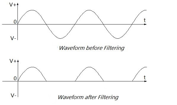
Figure 5. Half-wave Rectifier Circuit Waveform before and after Filtering
2. Full-wave Rectifier Circuit
Since half cycle is lost in half-wave rectification, the efficiency is limited. A full-wave bridge rectifer can solve the problem.
Compared with half-wave rectification, full-wave rectification uses one more diode. However, the transformer here is with a central axis, which uses the unidirectional conductivity of the diode.

Figure 6. Full-wave Rectifier Circuit Schematic Diagram
Let's analyze this principle. If the AC is in the positive half cycle, the voltage at point a is higher than the voltage at point b, then diode D1 will be turned on and diode D2 will be cut off. So the current will only flow from point a, through the diode D1 and the resistor RL, and finally to the central axis of the transformer.
If the AC is in the negative half cycle, the voltage at point b is higher than the voltage at point a, diode D2 will be turned on and diode D1 will be cut off. So the current will only flow from point b, and through diode D2 and resistor RL, finally to the central axis of the transformer.
Repeating these cycles achieves the filtering. The following picture shows the waveform before and after filtering.
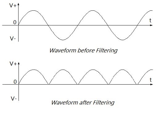
Figure 7. Full-wave Rectifier Circuit Waveform before and after Filtering
3. Bridge Rectifier Circuit
The bridge rectifier circuit is more complicated than the previous two. The schematic diagram is as follows. The simple bridge rectifier circuit consists of a transformer and the main rectifier bridge, and load.
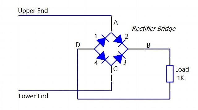
Figure 8. Bridge Rectifier Diagram-1
If the AC signal output is in the positive half cycle, under normal circumstances, the current flows to point A, facing diode 2 and diode 1.

Figure 9. Bridge Rectifier Circuit Schematic Diagram-2
However, due to the high voltage at point A, diode 1 is in the off state and diode 2 is in the on the state. So the current will flow through diode 2, then flow out from point B and then reach point D through the load.

Figure 10. Bridge Rectifier Circuit Schematic Diagram-3
At first glance, both diode 1 and diode 4 can be turned on, but the current is flowing from point A into the rectifier bridge and then through the load. The voltage will decrease after the current flows through the load, so the voltage at point D is far lower than the voltage at point A, and diode 4 is turned on and diode 1 is turned off. Finally, the current flows into the lower end of the transformer.
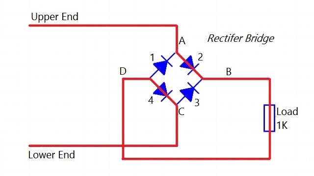
Figure 11. Bridge Rectifier Circuit Schematic Diagram-4
When the voltage at the lower end is higher than the voltage at the higher end, the current reaches point C.

Figure 12. Bridge Rectifier Circuit Schematic Diagram-5
Also, because the voltage at point C is high, diode 4 is in the off state and diode 3 is in the on state. The current will flow through diode 3 from point B, and then reach point D through the load.

Figure 13. Bridge Rectifier Circuit Schematic Diagram-6
Similar to the positive half-cycle, at first glance, diode 1 and diode 4 can be turned on. But since the current is flowing from point C into the rectifier bridge then through the load, the voltage at point D is far lower than point C, so diode 1 is turned on and diode 4 is turned off. Finally, the current flows into the upper part of the transformer.

Figure 14. Bridge Rectifier Circuit Schematic Diagram-7
Advantages of Bridge Rectification
Compared with full-wave rectification, bridge rectification has many advantages.
Full-wave rectification requires a transformer with a central axis, while bridge rectification does not have this requirement.
When the diode is in the off state, the voltage on the two ends of the bridge rectifier diode is less than half that of full-wave rectification. So the performance requirements of the bridge rectifier diode are not so high.
VI Rectifier Diode Replacement and Inspection
1. Replacement
After the rectifier diode is damaged, it can be replaced with a rectifier diode of the same model or another model with the same parameters.
Generally, rectifier diodes with high withstand voltage (reverse voltage) can replace rectifier diodes with low withstand voltage. And rectifier diodes with low withstand voltage cannot replace one with high withstand voltage.
A diode with a high rectification current can replace one with a low rectification current, while a diode with a low rectification current value cannot replace a diode with a high rectification current value.
2. How to Test a Bridge Rectifier
(1) Remove all the rectifier diodes in the rectifier.
(2) Use the 100×R or 1000×R ohm range of a multimeter to measure the two lead wires of the rectifier diode. Then swop the head and the tail and test again.
(3) If the resistance value measured twice has a great difference, it indicates that the diode is good (except for diodes with soft breakdown).
If the resistance value measured twice is small and almost the same, it means the diode has been broken down and cannot be used.
If the resistance value measured twice is infinite, it means that the diode has been internally disconnected and cannot be used.
Recommended Articles:
 UTMEL
UTMEL
We are the professional distributor of electronic components, providing a large variety of products to save you a lot of time, effort, and cost with our efficient self-customized service. careful order preparation fast delivery service
1.What is rectifier diode?
A rectifier diode is a two-lead semiconductor that allows current to pass in only one direction. Rectifier diodes are a vital component in power supplies where they are used to convert AC voltage to DC voltage.
2.How does a rectifier diode work?
The diode allows current in forwarding bias conditions and blocks current in reverse bias condition. In simple words, a diode allows current in just one direction. This unique property of the diode allows it to act sort of a rectifier by converting an alternating current to a DC source.
3.How do rectifiers work?
A rectifier is an electrical device that converts alternating current (AC), which periodically reverses direction, to direct current (DC), which flows in only one direction. The reverse operation is performed by the inverter. The process is known as rectification, since it "straightens" the direction of current.
4.What is the difference between diode and rectifier?
A diode is a switching device, while a rectifier is generally used for the conversion of AC voltage to DC voltage. A diode allows the flow of current only when it is forward biased. The diode blocks the reverse flow of current. A rectifier, on the other hand, consists of a transformer, a diode, and a filter circuit.
5.What are the three types of rectifier?
Single Phase & Three Phase Rectifiers.
Half Wave & Full Wave Rectifiers.
Bridge Rectifiers.
Uncontrolled & Controlled Rectifiers.
 All You Need to Know About Rectifier CircuitUTMEL24 April 202517609
All You Need to Know About Rectifier Circuit
Read More 15 Key Elements of Diode SelectionUTMEL26 November 202118902
Hello everyone, I am Rose. Welcome back to the new post today. Diodes are one of the most common components in our circuit boards. So, what factors should be considered when selecting models?
Read More What is a PIN Diode?UTMEL04 February 202110229
While diodes with a simple PN junction are by far the most common type of diode in operation, in a variety of applications, other forms of diode may be used. The PIN diode is one type that is used for a number of circuits. In a variety of places, this diode type is used. For RF switching, the PIN diode is very fine, and the PIN structure in photodiodes is very useful as well.
Read More Microwave Diode: Introduction and TypesUTMEL07 January 202126026
Microwave diodes are diodes that work in the microwave frequency band. It is a solid-state microwave device. Microwave band usually refers to the frequency from 300 MHz to 3000 GHz. After the discovery of the point contact diode effect at the end of the 19th century, microwave diodes such as PIN diodes, varactor diodes, and Schottky diode tubes appeared one after another. Microwave diodes have the advantages of small size and high reliability, and are used in microwave oscillation, amplification, frequency conversion, switching, phase shifting and modulation.
Read More What Determines the Maximum Operating Frequency of a Diode?UTMEL29 June 202212925
Hello, wish you a wonderful day. In this essay, we first pose the following query: what determines the diode's maximum operating frequency? In regards to the solution, the first thing we need to understand is that the junction capacitance and the reverse recovery time of the diode are two distinct concepts. The charging and discharging times of the junction capacitance cannot match the reverse recovery time. You say that, why? Let's start by taking a look at these facts.
Read More
Subscribe to Utmel !
![BLM18KG601SH1D]() BLM18KG601SH1D
BLM18KG601SH1DMurata Electronics
![BLM15BC121SN1D]() BLM15BC121SN1D
BLM15BC121SN1DMurata Electronics
![MMZ2012S800AT000]() MMZ2012S800AT000
MMZ2012S800AT000TDK Corporation
![MMZ1608D121CTAH0]() MMZ1608D121CTAH0
MMZ1608D121CTAH0TDK Corporation
![NFM3DCC102R1H3L]() NFM3DCC102R1H3L
NFM3DCC102R1H3LMurata Electronics
![NFM31KC223R1H3L]() NFM31KC223R1H3L
NFM31KC223R1H3LMurata Electronics
![MMZ1608B102CTD25]() MMZ1608B102CTD25
MMZ1608B102CTD25TDK Corporation
![MMZ1608Y600BTA00]() MMZ1608Y600BTA00
MMZ1608Y600BTA00TDK Corporation
![HFCN-1760]() HFCN-1760
HFCN-1760Mini-Circuits
![BLM03BD750SN1D]() BLM03BD750SN1D
BLM03BD750SN1DMurata Electronics