Introduction to Silicon Controlled Rectifier
What is Silicon Controlled Rectifier?
Catalog
Ⅰ SCR structure
There are two types of SCRs:SCR(unidirectional control) and TRIAC(bidirectional control). The TRIAC is structurally equivalent to two unidirectional SCR connected in reverse, and this SCR has a bidirectional conduction function. Its on-off state is determined by the Gate. Adding a positive pulse (or negative pulse) to the control terminal G can make it conduct in the positive (or reverse) direction. The advantage of this device is that the control circuit is simple and there is no reverse withstand voltage problem, so it is particularly suitable for use as an AC contactless switch.
Unidirectional silicon controlled rectifier: it is commonly referred to as an ordinary SCR. It is composed of four layers of semiconductor materials, with three PN junctions and three external electrodes: the first layer of P-type semiconductor leads the electrode which is called anode A, the electrode from the third layer of P-type semiconductor is called control electrode G, and the electrode from the fourth layer of N-type semiconductor is called cathode K. From the circuit symbol of the SCR, it can be seen that it is a unidirectional conductive device like a diode. The key is the addition of a control electrode G, which makes its working characteristics completely different from the diode.

The structure and symbol of SCR
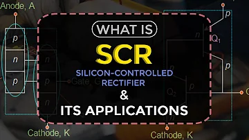
Regardless of the shape of the silicon-controlled rectifier, their die is a four-layer P1N1P2N2 structure composed of P-type silicon and N-type silicon. see picture below. It has three PN junctions (J1, J2, J3), the anode A is drawn from the P1 layer of the J1 structure, the cathode K is drawn from the N2 layer, and the control electrode G is drawn from the P2 layer, so it is a four-layer three-terminal semiconductor device.

SCR structure diagram and symbol diagram
When we analyze the principle, we can regard it as consisting of a PNP tube and an NPN tube. The equivalent diagram is shown in the figure.

SCR structural elements and equivalent diagrams
TRIAC: TRIAC is a silicon controlled rectifier device, also called bidirectional thyristor. A TRIAC is a bidirectional, three-terminal dual, back-to-back Thyristor (SCR) switch. It can switch the current in either direction by applying a small current of either polarity between the gate and main terminal two. The TRIAC is fabricated by integrating two thyristors in an inverse parallel connection. This device can realize non-contact control of alternating current in the circuit, and control large current with small current, and has the advantages of no spark, fast action, long life, high reliability, and simplified circuit structure. The TRIAC is very similar to the ordinary SCR, and it also has three electrodes. However, except that one of the electrodes G is still called the control electrode, the other two electrodes are usually no longer called anode and cathode, but are collectively called the main electrodes Tl and T2. Its symbol is also different from ordinary SCR. It is drawn by connecting two SCRs in reverse, as shown in the figure.

TRIAC structure and circuit
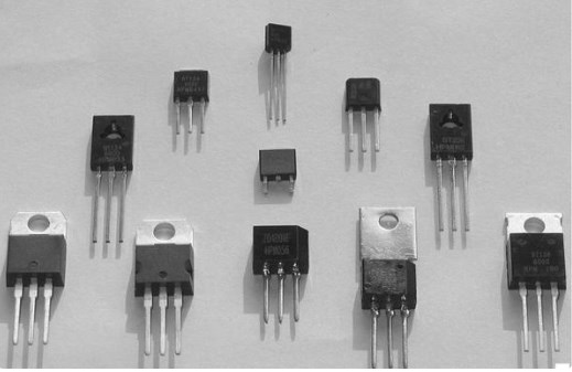
The specifications, models, shapes, and electrode pin arrangements of TRIACs vary from manufacturer to manufacturer, but most of their electrode pins are arranged from left to right in the order of T1, T2, and G (when observed, the electrode Pin down, facing the side marked with characters). The shape and electrode pin arrangement of the most common plastic-encapsulated TRIACs on the market are shown in the figure below.

The shape of the TRIAC
Ⅱ SCR characteristics
In order to be able to intuitively understand the working characteristics of the SCR, we first look at the Figure below. The SCR VS is connected in series with the small bulb EL and connected to the DC power supply through the switch S. Note that anode A is connected to the positive terminal of the power supply, the cathode K is connected to the negative terminal of the power supply, and the control terminal G is connected to the positive terminal of the 1.5V DC power supply through the button switch SB (KP1 type SCR is used here. If the KP5 type is used, it should be connected to 3V DC power supply positive). This connection between the thyristor and the power supply is called a forward connection, that is, the positive voltage is applied to the thyristor anode and control electrode. Turn on the power switch S, the small light bulb does not light up, indicating that the SCR is not conducting; press the button switch SB again to input a trigger voltage to the control electrode, and the small light bulb lights up, indicating that the SCR is conducting. What inspiration did this demonstration experiment give us?

The SCR VS and small bulb EL in series
This experiment tells us that to make the thyristor turn on, one is to apply a forward voltage between its anode A and cathode K, and the other is to input a positive trigger voltage between its control electrode G and cathode K. After the SCR is turned on, release the button switch, remove the trigger voltage, and still maintain the on the state.
However, if a reverse voltage is applied to the anode or the gate, the SCR cannot be turned on. The function of the gate is to turn on the SCR by applying a positive trigger pulse, but not to turn it off. So, what method can be used to turn off the conducting thyristor? To turn off the conducting thyristor, you can disconnect the anode power supply (switch S in Figure) or make the anode current less than the minimum to maintain conduction Value (called the holding current). If an AC voltage or a pulsating DC voltage is applied between the anode and the cathode of the SCR, the SCR will turn off by itself when the voltage crosses zero
Ⅲ Classification
There are many classification methods for SCRs.
(1) Classified by turn-off, turn-on, and control methods: SCRs can be classified into ordinary SCR, bidirectional SCR, reverse-conducting SCR, GTO, BTG, temperature control SCR and light control SCR, etc.
(2) Classified by pin and polarity: SCR can be divided into two-terminal SCR, three-terminal SCR, and four-terminal SCR according to its pin and polarity.
(3) Classified by packaging form: SCRs can be divided into three types according to their packaging form: metal packaged SCR, plastic-packaged SCR, and ceramic packaged SCR. Among them, metal-encapsulated SCRs are divided into bolt-shaped, flat-plate, and round-shell-shaped; plastic-encapsulated SCRs are divided into two types with heat sink and without a heat sink.
(4) Classified by current capacity: SCRs can be divided into three types: high-power SCR, medium-power SCR, and low-power SCR according to current capacity. Generally, high-power SCRs are mostly packaged in metal shells, while medium and low-power SCRs are mostly packaged in plastic or ceramic packages.
(5) Classified by turn-off speed: SCR can be divided into ordinary SCR and high-frequency (fast) SCR according to its turn-off speed.
(6) Zero-crossing trigger-generally power adjustment, that is, when the sine AC voltage phase is triggered at the zero-crossing point, it must be triggered at the zero-crossing point, and the SCR is turned on.
(7) Non-zero-crossing trigger-the thyristor can be triggered to turn on regardless of the phase of the AC voltage. The common one is the phase shift trigger, that is, by changing the conduction angle (angle phase) of the sinusoidal AC current to change the output percentage.
1 What is the difference between SCR and thyristor?
A thyristor is a 4 layer device formed by the alternate combination of p and n-type semiconductor materials. It is a device used for rectification and switching purposes. SCR is the most-used member of the thyristor family and it is the name commonly used when we talk about thyristors.
2 What is SCR and its types?
A silicon-controlled rectifier or semiconductor-controlled rectifier is a four-layer solid-state current-controlling device. The name "silicon controlled rectifier" is General Electric's trade name for a type of thyristor. SCRs are mainly used in electronic devices that require control of high voltage and power.
3 Why SCR is called Thyristor?
In many ways, the Silicon Controlled Rectifier, SCR, or just Thyristor as it is more commonly known, is similar in construction to the transistor. In fact, the circuit symbol for the thyristor suggests that this device acts like a controlled rectifying diode.
4 How do you trigger an SCR?
To trigger, or fire, an SCR, the voltage must be applied between the gate and cathode, positive to the gate and negative to the cathode. When testing an SCR, a momentary connection between the gate and anode is sufficient in polarity, intensity, and duration to trigger it.
5 What is the difference between SCR and diode rectifier?
Both devices have terminals called 'anode' and 'cathode' but SCR has an additional terminal called 'gate'. Both these devices have application dependant advantages. A diode is the simplest semiconductor device and it consists of two semiconductor layers (one P-type and one N-type) connected to each other.
6 What is thyristor family?
The complete list of thyristor family members include diac (bidirectional diode thyristor), TRIAC (bidirectional triode thyristor), SCR (silicon controlled rectifier), Shockley diode, SCS (silicon controlled switch), SBS (silicon bilateral switch), SUS (silicon unilateral switch) also known as complementary SCR or CSCR.
7 What are the modes of operation of silicon-controlled rectifier?
There are three modes of operation for an SCR depending upon the biasing given to it: Forward blocking mode (off state) Forward conduction mode (on state) Reverse blocking mode (off state)
 What is a Thyristor?UTMEL11 December 20209212
Thyristor, also known as silicon controlled rectifier (SCR), can control its conduction through a signal, but cannot control its turn-off, so it is called a semi-controlled device. The name thyristor often refers specifically to a basic type of thyristor, but broadly speaking, thyristors also include many derivative devices, such as Tri-Electrode AC switch (TRIAC), Fast Switching Thyristor (FST), Reverse-Conducting Thyristor (RCT) and Light-Triggered Thyristor (LTT).
Read More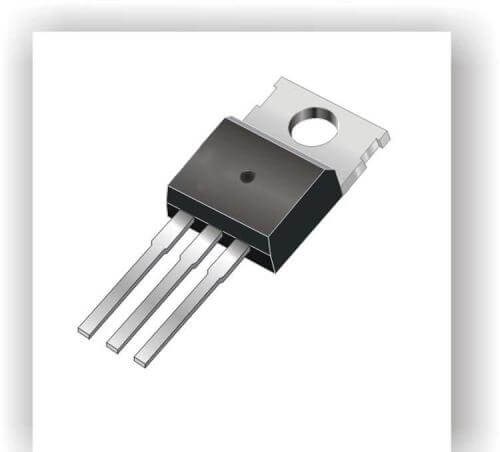 Introduction to Silicon Controlled RectifierUTMEL25 September 20206945
Silicon Controlled Rectifier, abbreviated as SCR, is a high-power electrical component, also known as a thyristor. It has the advantages of small size, high efficiency and long life. In the automatic control system, it can be used as a high-power drive device to realize the control of high-power equipment with low-power controls. It has been widely used in AC and DC motor speed control system, power control system and servo system.
Read More An Introduction to DIACsRakesh Kumar, Ph.D.21 May 20252386
This article explores DIACs, detailing their structure, operating characteristics, and applications in power electronics as bi-directional semiconductor switches for AC control circuits.
Read More Comparing Heat Sink Types for Modern ApplicationsUTMEL19 July 20251388
Compare active and passive heat sinks, their materials, and designs to find the best cooling solution for electronics, balancing performance and cost.
Read More
Subscribe to Utmel !


