An Introduction to DIACs
In power electronics, various semiconductor devices serve specific functions in controlling electrical power. The DIAC is one such fundamental component, particularly valuable in AC control applications where bi-directional switching is required. These components are members of the thyristor device family. While structurally related to TRIACs, DIACs lack the defining gate terminal that would otherwise allow direct switching control.
What is a DIAC?
A DIAC (DIode Alternating Current) is a two-terminal power electronics component that functions as a full-wave or bi-directional semiconductor switch. Unlike regular diodes, DIACs conduct in both forward and reverse polarities once a specific threshold voltage is reached. The device is alternatively known as a symmetrical trigger diode.
They are commonly used in AC timers, dimmers, and motor speed control circuits, typically working alongside a TRIAC. In power electronics, DIACs fall into the category of uncontrollable switches since the external power circuit alone dictates when they turn on or off.
DIAC Symbol
The circuit symbol consists of two triangles held between two lines, representing two diodes connected in reverse parallel, as shown in Fig. 1. The two terminals are usually designated as:
● Main Terminal 1 (MT1) or Anode 1 (A1)
● Main Terminal 2 (MT2) or Anode 2 (A2)
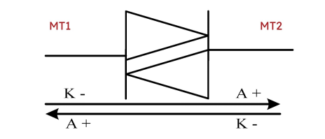
Fig. 1 Diagrammatic illustration of DIAC symbol. Source: MDPI
DIAC Structure
Manufacturers produce DIACs in two configurations:
● Three-layer structures
● Five-layer structures
The three-layer design dominates the market due to its nearly symmetrical operating characteristics, sufficient improvement in switching characteristics, and consistent break-over voltage of approximately 30V.
DIACs are also available in a five-layer configuration. This structure produces a comparable voltage-current (I-V) characteristic to the three-layer version but works through a different mechanism. The five-layer DIAC functions similarly to two break-over diodes arranged in an opposing, back-to-back configuration. The physical structure can be viewed as two PNPN structures connected in parallel.
DIAC Characteristics and Operation
DIACs have a unique operating characteristic defined by their breakover voltage (VBO). While conventional diodes conduct current in a single direction immediately upon forward biasing, DIACs remain non-conductive in both directions until the applied voltage reaches a specific breakover threshold. The relationship between voltage and current for a DIAC can be understood through these key points:
● Normal state: DIACs do not conduct current until a specific threshold is reached.
● Break-over voltage (VBO): Typically between 25V and 48V, depending on the device.
● Conduction state: Once VBO is exceeded, the DIAC begins to conduct
● Holding current (IH): The DIAC remains in conduction until the current drops below this level.
DIACs function as bidirectional devices, responding to both the positive and negative portions of an AC waveform. During each half-cycle, the DIAC behaves identically, with only an operational difference in current direction. This two-way conduction property is clearly visible in the device's voltage-current characteristic curve, as shown in Fig. 2.
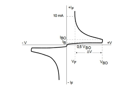
Fig. 2 Diagrammatic illustration voltage-current characteristic curve of the DIAC. Source: STMicroelectronics DB3
Applications
DIACs primarily serve in power control applications, though they also appear in transient suppression networks and various specialized electronic circuits where their unique triggering capabilities fulfill essential functions.
TRIAC Triggering
The primary use of DIACs is improving TRIAC performance in AC switching circuits. When connected to a TRIAC's gate circuit, DIACs help balance triggering action during positive and negative AC half-cycles.
The circuit diagram in Fig. 3 illustrates a fundamental DIAC-TRIAC arrangement used for AC power control applications. The components form a simple but effective dimmer or speed control circuit:
● AC Source: Provides alternating current input power.
● LOAD: Represents the device being controlled (such as a light bulb or motor).
● R: Variable resistor that allows adjustment of power delivery.
● TRIAC: Main switching element that controls current flow to the load.
● DIAC: A triggering device that ensures consistent TRIAC activation.
● C1: A capacitor that forms an RC timing network with the variable resistor.
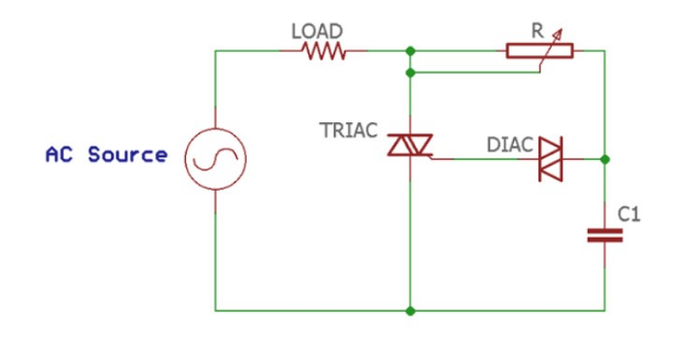
Fig. 3 Diagrammatic illustration of TRIAC Triggering using DIAC. Source: IOP Conference Series: Earth and Environmental Science
The circuit operates through phase control. During each AC half-cycle, capacitor C1 charges through the variable resistor R. When the voltage across C1 reaches the DIAC's breakover threshold, the DIAC conducts and triggers the TRIAC's gate, allowing current to flow to the load.
By adjusting R, users can modify when, in each half cycle, the TRIAC activates, effectively controlling power delivery to the connected device. This configuration represents one of the most common practical applications of DIACs in consumer and industrial electronics.
Dimmer Circuits:
DIACs serve as core components in residential and commercial dimming systems, where they trigger at exact voltage levels to regulate illumination.
Fluorescent Lamp Starters
In starter circuits for fluorescent fixtures, DIACs create the initial discharge needed for lamp ignition.
Pulse Generation
The precise breakdown voltage properties of DIACs make them suitable for generating timing pulses in electronic clocks and delay circuits.
Voltage-to-Frequency Conversion:
DIACs transform varying voltage levels into frequency-based outputs due to their well-defined switching points.
An effective DIAC to consider
DB3, DB4, and SMDB3 DIACS
These DIACs are trigger devices with a fixed voltage reference, commonly used for triggering TRIACs or SCRs in light dimmers, motor controls, and lamp ballasts. The main specification is the breakover voltage (VBO), which is the voltage at which the DIAC switches from a high-resistance to a low-resistance state, allowing current to flow.
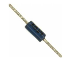
Fig. 4 STMicroelectronics DB3. Source: Utmel
For the DB3 and SMDB3, the typical breakover voltage is 32 V, with a range from 28 V to 36 V. For the DB4, the typical breakover voltage is higher, at 40 V, with a range from 35 V to 45 V.
Summarizing the Key Points
● A DIAC is a bidirectional semiconductor switch that conducts in both directions once its breakover voltage is exceeded.
● DIACs feature a simple two-terminal structure with symmetrical operation in both directions.
● The primary applications of DIACs include TRIAC triggering, dimmer circuits, and starter circuits for fluorescent lamps.
Reference
Yusran, N., & Armanda, A. D. (2021). Design and testing of 1 phase semi-controlled rectifier circuit (experiment scale): a part of green laboratory project. IOP Conference Series Earth and Environmental Science, 926(1), 012045. https://doi.org/10.1088/1755-1315/926/1/012045
Jiya, I. N., & Gouws, R. (2020). Overview of Power Electronic Switches: A summary of the past, State-of-the-Art and Illumination of the Future. Micromachines, 11(12), 1116. https://doi.org/10.3390/mi11121116
Thyristor, Triac and Diac https://www.researchgate.net/publication/321137100_Thyristor_Triac_and_Diac
STMicroelectronics DB3- https://www.utmel.com/productdetail/stmicroelectronics-db3-5656090
Learning Electronics. (2020, April 16). DIAC(Diode in AC) in English [Video]. YouTube. https://www.youtube.com/watch?v=J0Jib3gxbSQ
ElectronicsNotes. (2024, January 16). Understanding DIACs [Video]. YouTube. https://www.youtube.com/watch?v=hCl4WqgFFGE
Electrical Electronics Applications. (2023, March 26). What is a DIAC? How DIACs Work? (DIAC Tutorial) [Video]. YouTube. https://www.youtube.com/watch?v=SS31aVOziH0
 What is a Thyristor?UTMEL11 December 20209102
Thyristor, also known as silicon controlled rectifier (SCR), can control its conduction through a signal, but cannot control its turn-off, so it is called a semi-controlled device. The name thyristor often refers specifically to a basic type of thyristor, but broadly speaking, thyristors also include many derivative devices, such as Tri-Electrode AC switch (TRIAC), Fast Switching Thyristor (FST), Reverse-Conducting Thyristor (RCT) and Light-Triggered Thyristor (LTT).
Read More Introduction to Silicon Controlled RectifierUTMEL25 September 20206878
Silicon Controlled Rectifier, abbreviated as SCR, is a high-power electrical component, also known as a thyristor. It has the advantages of small size, high efficiency and long life. In the automatic control system, it can be used as a high-power drive device to realize the control of high-power equipment with low-power controls. It has been widely used in AC and DC motor speed control system, power control system and servo system.
Read More An Introduction to DIACsRakesh Kumar, Ph.D.21 May 20252163
This article explores DIACs, detailing their structure, operating characteristics, and applications in power electronics as bi-directional semiconductor switches for AC control circuits.
Read More Comparing Heat Sink Types for Modern ApplicationsUTMEL19 July 20251295
Compare active and passive heat sinks, their materials, and designs to find the best cooling solution for electronics, balancing performance and cost.
Read More
Subscribe to Utmel !


