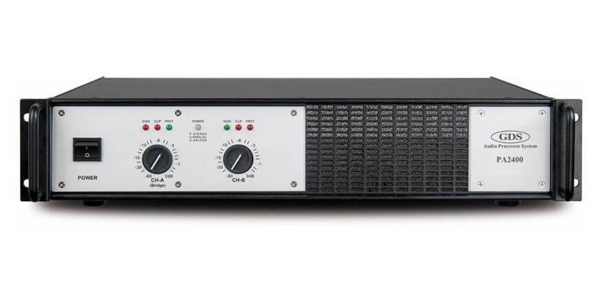
Basic Introduction to Power Amplifier

POWER AMPLIFIER (PART-1) : BASIC CONCEPTS (2018)
2026 Executive Summary
A Power Amplifier (PA) is an electronic device designed to increase the magnitude of a given input signal—converting low-power DC voltage into a high-power AC signal to drive loads like speakers or RF transmitters. In the 2026 landscape, the industry has shifted heavily toward high-efficiency Class D and GaN (Gallium Nitride) based architectures, offering superior thermal management and energy efficiency (>90%) for modern 5G/6G networks and high-resolution audio systems.
Catalog
Ⅳ Key Performance Indicators (KPIs)
| |
Ⅰ How does a Power Amplifier Work?
A power amplifier operates by leveraging the control function of a transistor (BJT, FET, or modern GaN HEMT) to convert DC power supply energy into an output current that precisely mimics the input signal's waveform but at a higher amplitude. Essentially, the collector (or drain) current is regulated by the base (or gate) signal.
In a standard transistor configuration, the collector current is typically β (beta) times the base current, where β represents the amplification factor. When a small audio or RF signal is injected into the base, the transistor modulates the larger current flowing from the power supply through the collector. This signal is then isolated via a DC blocking capacitor to strip the direct current voltage, resulting in a pure, amplified AC signal capable of driving loads like loudspeakers or antennas.

Figure 1. Power amplifier circuit diagram
Ⅱ What are the Main Types of Power Amplifiers?
Amplifiers are classified into "Classes" (A, B, AB, C, D, T) based on their conduction angle—the portion of the input signal cycle during which the amplifying device conducts current.
Class A Amplifier (High Fidelity / Low Efficiency):
The Class A amplifier is defined by its operating point (Q-point) being set in the middle of the load line, meaning the transistor conducts for the full 360° of the input cycle. While this results in minimal crossover distortion and high linearity (ideal for audiophiles), it is highly inefficient. Even in 2026, the theoretical maximum efficiency remains 25%, with the rest dissipated as heat.
Class B Amplifier (Push-Pull Efficiency):
Class B amplifiers bias the transistors at cutoff (0V), meaning no power is consumed when no signal is present. It uses a push-pull arrangement where one transistor handles the positive half-cycle and another handles the negative half-cycle. This boosts theoretical efficiency to roughly 78.5%. However, it suffers from "crossover distortion" at the zero-crossing point (0.6V to -0.6V), making it less desirable for high-fidelity audio today.
Class AB Amplifier (The Analog Standard):
Class AB acts as a hybrid, conducting slightly more than 180° (half cycle). By applying a small bias voltage, it eliminates the crossover distortion of Class B while maintaining much better efficiency than Class A. Until the dominance of digital amplification, this was the standard for home audio.
Class C Amplifier (RF Applications):
In Class C, the transistors conduct for less than half a cycle (< 180°). This creates massive distortion, making it unsuitable for audio. However, with an LC parallel resonant circuit (tank circuit) as a load, it is incredibly efficient (up to 98%) for Radio Frequency (RF) transmission. It remains a staple in RF transmitters and frequency multipliers.
Class D Amplifier (Modern Digital Standard):
By 2026, Class D amplifiers dominate the consumer electronics market. They function as binary switches, using Pulse Width Modulation (PWM) or Pulse Density Modulation (PDM) to switch transistors fully ON or fully OFF. This switching topology, often utilizing Gallium Nitride (GaN) FETs, results in negligible power loss during transitions.
2026 Advantages of Class D:
Efficiency exceeding 90-95% (minimal heat generation).
Compact form factor suitable for smartphones and wearables.
Low distortion levels that now rival traditional Class AB systems due to advanced feedback loops.
Class T Amplifier (Proprietary Variation):
Originally developed by Tripath, the "Class T" is a specialized variation of Class D that uses "Digital Power Processing" (DPP). Unlike standard fixed-frequency PWM, Class T uses adaptive algorithms and spread-spectrum switching frequencies to minimize noise and improve dynamic range. While the specific brand is historic, the concept of spread-spectrum digital amplification remains a high-end standard in 2026 audio engineering.
Ⅲ What Components Make Up a Power Amplifier?
A complete power amplification system is composed of three distinct stages, each preparing the signal for the final output.

Figure 2. Power amplifier system architecture
1. Preamplifier (Signal Conditioning): This stage has high input impedance (>10kΩ) to prevent loading the source device. It boosts the weak voltage signal to a line-level standard and often includes tone controls or equalization.
2. Driver Amplifier (Voltage Amplification): Acting as the bridge, this stage amplifies the voltage significantly to a level capable of driving the power transistors. It ensures the final stage has sufficient drive current to operate linearly.
3. Final Power Stage (Current Amplification): The critical stage that delivers current gain. It connects directly to the loudspeaker (load). In 2026, this stage often utilizes MOSFETs or GaN transistors to handle high power with minimal thermal loss.
Ⅳ Key Performance Indicators (KPIs)
Technical Specifications

Figure 3. Modern Power Amplifier Circuitry
To evaluate a power amplifier in 2026, five technical indices are paramount:
1. Rated Power (RMS): The continuous sine wave power output (measured in Watts/Channel) at a specific load (e.g., 8Ω) with less than 1% distortion. This is the only "true" measure of power, unlike peak marketing numbers.
2. Total Harmonic Distortion (THD): Indicates the purity of the signal. It measures the added harmonic noise relative to the fundamental frequency. High-end modern amps achieve THD lower than 0.005%.
3. Slew Rate: Measured in Volts/microsecond (V/μs), this defines how fast the amplifier can respond to rapid signal changes. A higher slew rate is essential for crisp transient response in High-Res Audio.
4. Damping Factor: The ratio of load impedance to the amplifier's internal source impedance (e.g., 8Ω / 0.04Ω = 200). A high damping factor allows the amp to control the speaker cone's motion tightly, preventing "boomy" bass.
5. Load Impedance Capability: Stable operation at lower impedances (2Ω or 4Ω) indicates a robust power supply and high-current capability, allowing the driving of complex multi-speaker arrays.
Performance Metrics
Whether for Home Cinema (AV) or Hi-Fi stereo, these performance benchmarks determine the listening experience:
Power Measurement Standards:
RMS (Root Mean Square): The continuous power output. This is the industry standard for comparison.
Peak Music Power Output (PMPO): A marketing metric often inflating capabilities by 5-8x the real RMS value. It represents a theoretical split-second burst before failure and should generally be ignored in professional contexts.
Frequency Response:
While the human ear hears 20Hz-20kHz, high-quality 2026 amplifiers often handle 10Hz-100kHz. This extended bandwidth ensures that phase shifts occur well outside the audible range, preserving the spatial imaging of the sound.
Signal-to-Noise Ratio (SNR):
Expressed in decibels (dB), this compares the signal level to background noise. An SNR >100dB is the benchmark for high-fidelity digital systems in 2026, ensuring that during quiet musical passages, no hiss is audible.
Ⅴ Where are Power Amplifiers Used in 2026?
Power amplifiers are the backbone of modern communication and entertainment ecosystems. In 2026, their application scope has expanded significantly beyond simple audio.
1. 5G and 6G Networks: RF power amplifiers are critical in Massive MIMO antenna arrays. These systems require high-efficiency devices (like Class F or inverse Class F) to handle the millimeter-wave frequencies used in 6G without overheating.
2. Electric Vehicles (EVs): Modern EVs use sophisticated power amplifiers not just for infotainment, but for Acoustic Vehicle Alerting Systems (AVAS) and active noise cancellation (ANC) to reduce road noise inside the cabin.
3. The Push for Efficiency (Class F & E): In RF applications, efficiency is the primary goal to extend battery life in IoT devices. Switching amplifiers like Class E and Class F utilize harmonic tuning networks to shape voltage and current waveforms (preventing overlap), theoretically achieving 100% drain efficiency. This technology is vital for the billions of connected sensors in the 2026 IoT landscape.
1.What is a power amplifier used for?
A power amplifier is an electronic amplifier designed to increase the magnitude of the power of a given input signal. The power of the input signal is increased to a level high enough to drive loads of output devices like speakers, headphones, RF transmitters, etc.
2.Which is the best power amplifier?
Behringer NX4-6000 QSC GX5 Crown XTi 4002 Samson Servo 120A Behringer KM750 Yamaha PX3 QSC RMX 1450a QSC GX7
3.How does a power amplifier work?
The power amplifier works on the basic principle of converting the DC power drawn from the power supply into an AC voltage signal delivered to the load. Although the amplification is high the efficiency of the conversion from the DC power supply input to the AC voltage signal output is usually poor.
4.Does a power amp make a difference?
It's possible for two amps with slightly different wattage ratings to sound different, but all things being equal, they won't produce a different volume. A better amp will make your speakers play louder and sound better, but it won't make bad speakers sound like good speakers.
5.What power amplifier do I need?
Generally you should pick an amplifier that can deliver power equal to twice the speaker's program/continuous power rating. This means that a speaker with a “nominal impedance” of 8 ohms and a program rating of 350 watts will require an amplifier that can produce 700 watts into an 8 ohm load.
 Introduction to MD8002A Audio AmplifierUTMEL27 March 20256801
The MD8002A is an audio power amplifier that uses a 5V DC power supply to provide 2.0 watts of continuous power to a BTL load with less than 10% distortion. It was created with the aim of providing high-quality o/p control with fewer components. It doesn't use any output coupling capacitors or bootstrap capacitors.
Read More Understanding the Low Noise Amplifier (LNA)UTMEL20 March 202516075
A low noise amplifier is an amplifier with a very low noise figure. It is generally used as a high-frequency or intermediate-frequency preamplifier for various types of radio receivers, as well as amplifying circuits for high-sensitivity electronic detection equipment.
Read More Introduction to Optical AmplifierUTMEL27 March 20257885
An optical amplifier is a subsystem product that can amplify optical signals in optical fiber communication systems. The principle of the optical amplifier is basically based on the stimulated radiation of the laser, which realizes the amplification effect by converting the energy of the pump light into the energy of the signal light.
Read More What is an Inverting Amplifier?UTMEL25 April 20259469
An inverting amplifier is a fundamental configuration of operational amplifiers where the output signal has opposite polarity to the input signal. This configuration uses an operational amplifier with its inverting input terminal receiving the input signal, while the non-inverting terminal is typically connected to ground. The primary function of this circuit is to amplify the input signal while inverting its phase by 180 degrees.
Read More Low-Power Design of Operational AmplifiersUTMEL27 March 20254654
Hello, this is Candy. With the rise in popularity of battery-powered electronics in recent years, analog circuit designers have been increasingly concerned about power usage. This article will cover how to use low-power op amps in system design, as well as low-power op amps with low supply voltage capabilities and their applications, as well as how to read and understand op amp data sheets appropriately. Circuit design with energy-saving technologies for more efficient device choices.
Read More
Subscribe to Utmel !
![MSMCG48AE3/TR]() MSMCG48AE3/TR
MSMCG48AE3/TRMicrochip Technology
![MF-R040-0-99]() MF-R040-0-99
MF-R040-0-99Bourns Inc.
![M5KP48CAE3/TR]() M5KP48CAE3/TR
M5KP48CAE3/TRMicrochip Technology
![TRF250-120]() TRF250-120
TRF250-120Littelfuse Inc.
![TBU-PL050-200-WH]() TBU-PL050-200-WH
TBU-PL050-200-WHBourns Inc.
![JANTX1N6059A/TR]() JANTX1N6059A/TR
JANTX1N6059A/TRMicrochip Technology
![MXPLAD30KP33A/TR]() MXPLAD30KP33A/TR
MXPLAD30KP33A/TRMicrochip Technology
![JANTX1N6128US]() JANTX1N6128US
JANTX1N6128USMicrochip Technology
![M5KP33CAE3/TR]() M5KP33CAE3/TR
M5KP33CAE3/TRMicrochip Technology
![M15KP280CAE3/TR]() M15KP280CAE3/TR
M15KP280CAE3/TRMicrochip Technology


