
 Product
 Brand
Brand Articles
 Tools
Tools
Introduction to TRIAC and TRIAC Dimmer

Triac, clearly explained.
Catalog
I What is TRIAC?
TRIAC is developed based on ordinary thyristors. It can not only replace two thyristors connected in parallel with reverse polarity, but also only needs one trigger circuit, which is an ideal AC switching device.
Why is it called "TRIAC"?
TRI: Triode (take the first three letters)
AC: AC semiconductor switch(take the first two letters)
The above two nouns are combined into "TRIAC"
II Main Parameters
The TRIAC can be considered as the integration of a pair of anti-parallel connected ordinary thyristors, and the working principle is the same as that of ordinary one-way thyristors.
The TRIAC has two main terminals T1 and T2, and a gate G. The gate enables the device to trigger conduction in both the positive and negative directions of the main electrode, so the TRIAC has symmetrical volt-ampere characteristics in the first and third quadrants.

Figure 1. TRIAC Symbol
The positive and negative trigger pulses applied to the TRIAC gate can trigger the tube to turn on, and there are four trigger modes.
In the application, its main parameters need to be grasped for an appropriate selection, and corresponding measures should be taken to meet the requirements of each parameter.
1. Select withstand voltage level: Usually, the smaller value between VDRM (off-state repetitive peak voltage) and VRRM (repetitive peak reverse voltage) is marked as the rated voltage of the device. In selection, the rated voltage should be 2 to 3 times the normal working peak voltage as the allowable operating overvoltage margin.
2. Determine the current: Since TRIAC is usually used in AC circuits, they do not use average values but use effective values to represent their rated current values. Because the overload capacity of the thyristor is smaller than that of general electromagnetic devices, the current value of the thyristor used in general household appliances is 2 to 3 times the actual working current value.
At the same time, the off-state repetitive peak voltage VDRM and the reverse repetitive peak voltage VRRM the TRIAC bears should be less than the IDRM and IRRM specified by the device.
3. Selection of on-state (peak) voltage VTM: It is the transient peak voltage drop of TRIAC at a specified multiple of rated current. In order to reduce the heat loss of the TRIAC, a TRIAC with a small VTM should be selected as much as possible.
4. Holding Current: IH is the minimum principle current necessary to maintain the thyristor in the on-state, which is related to the junction temperature. The higher the junction temperature, the smaller the IH.
5. Rate of Voltage Rise Resistance: dv/dt refers to the rising slope of the voltage in the off state, which is a key parameter to prevent false triggering. If this value exceeds the limit, it may lead to the misconduction of the SCR.
III TRIAC VS. SCR
SCR is the abbreviation for the silicon-controlled rectifier. SCRs are available in the unidirectional, bidirectional, turn-off, and light-controlled types. It has a small size, lightweight, high efficiency, long life, and is convenient for control, which is widely used in various automatic control and high-power electrical energy conversion occasions such as controlled rectifiers, voltage regulators, and inverters, and non-contact switches.

Figure 2. SCR Symbol
Both the unidirectional thyristor and the TRIAC have three terminals. Unidirectional SCRs have a cathode (K), an anode (A), and a gate (G). The TRIAC is equivalent to two single-direction thyristors in a reverse parallel connection. That is, one of the unidirectional silicon anodes is connected to the other's cathode, and its leading end is called T1, and one of the unidirectional silicon cathodes is connected to the other's anode, and its leading end is called T2, and the remainder is the gate (G).
The unidirectional thyristor is a kind of controllable rectifier electronic component, which can be changed from off to on under the action of the external control signal, but once it is on, the external signal cannot turn it off, unless we remove the load or reduce the voltage across it.
Unidirectional SCR is a four-layer three-terminal semiconductor device composed of three PN junctions. Compared with a diode with one PN junction, the forward conduction of the one-way SCR is controlled by the current of the control electrode; compared with the transistor with two PN junctions, the SCR does not amplify the control electrode current.
The TRIAC is turning on and off in two directions. It is essentially two anti-parallel unidirectional thyristors, composed of NNPPN five-layer semiconductors by four PN structures with three terminals.
Since the structure of the main electrode is symmetrical (all led from the N layer), its terminals are not called anode and cathode respectively like unidirectional thyristors. Instead, the one that is closer to the control electrode is called the first terminal T1, and the other is called the second terminal T2.
The main disadvantage of TRIAC is the poor ability to withstand the voltage rise rate. This is because when it is turned on in one direction, the carriers in each layer of the silicon chip have not returned to the position of the off state, and corresponding protective measures must be taken.
TRIAC components are mainly used in AC control circuits, such as temperature control, light control, explosion-proof AC switches, and the TRIAC motor control circuit and commutation circuit.
IV How to Install TRIAC
For TRIAC with a small load or short current duration (less than 1 second), it can work in free space. But in most cases, it needs to be installed on a radiator. In order to reduce the thermal resistance, the thyristor and the radiator should be coated with heat-conducting silicone grease.
There are three main methods to fix the TRIAC to the radiator, clamp crimping, bolting, and riveting. The installation tools for the first two methods are easy to obtain. In many cases, riveting is not a recommended method.
1. Clip Crimping: It is a recommended method, with minimum thermal resistance. The clamp exerts pressure on the plastic package of the device. The same applies to non-insulated packages (sot82 and sot78) and insulated packages (sot186 f-pack and newer sot186a x-pack). Note that sot78 is to220ab.
2. Bolting: The sot78 component is with m3 installation parts, including rectangular gaskets, which are placed between the bolt head and the joint piece. No force should be applied to the plastic body of the device.
● During the installation process, the screwdriver must not exert any force on the plastic body of the device;
● The surface of the heat sink in contact with the joint piece should be treated to ensure flatness, and the allowable deviation at 10mm should be 0.02mm;
● The installation torque (with gasket) should be between 0.55nm and 0.8nm;
● Avoid the use of self-tapping screws, because extrusion may cause bulges around the mounting holes and affect the thermal contact between the device and the heat sink.
In this installation method, the installation torque cannot be controlled. The device should be mechanically fixed first, and then the leads should be soldered. This can reduce undue stress on the leads.
V Precautions in Use
1. In order to turn on the TRIAC, the gate current must no less than IGT until the load current is no less than IL. This condition must be met and considered according to the lowest temperature that may be encountered.
2. Remember to disconnect the TRIAC switch.
3. When designing a TRIAC circuit, avoid the 3+ quadrant (WT2-, +) whenever possible.
4. In order to reduce clutter absorption, the length of the gate connection wires should be minimized, and the return line is directly connected to MT1 (or cathode). If using hardwire, use spiral double wire or shielded wire.
Add a resistance of 1kΩ or less between the gate and MT1. And a resistor is connected in series between the high-frequency bypass capacitor and the gate. Another solution is to use H series low-sensitivity TRIAC.
5. If dVD/dt or dVCOM/dt may cause problems, add an RC buffer circuit between MT1 and MT2. If high dICOM/dt may cause problems, add an inductor with few mH in series with the load. Another solution is to use Hi-Com TRIAC.
6. If the VDRM of the TRIAC is likely to be exceeded during a serious and abnormal power supply transient, one of the following measures is adopted:
● Connect an unsaturated inductor of a few μH in series with the load to limit dIT/dt;
● Connect the MOV to the power supply and add a filter circuit on the power supply side.
7. Choose a good gate trigger circuit to avoid the 3-quadrant working condition can maximize the dIT/dt endurance of the TRIAC.
8. If the dIT/dt of the TRIAC may be exceeded, it is best to connect an ironless inductor of a few μH or a thermistor with a negative temperature coefficient in series with the load. Another solution: use zero voltage to turn on the resistive load.
9. When the device is fixed to the heat sink, avoid stressing the TRIAC. Fix and then solder the leads. Do not put the rivet mandrel on the side of the device interface sheet.
10. In order to work reliably for a long time, Rthj-a should be kept low enough to maintain Tj not higher than Tjmax, whose value corresponds to the highest possible ambient temperature.
VI TRIAC Application
TRIAC can be widely used in industries, transportation, household appliances, and other fields to achieve AC voltage regulation, TRIAC speed control, AC switches, turning on and off automatic street lights, temperature control, desk lamp dimming, stage dimming, and other functions.
It also It is used in the solid-state relay (SSR) and solid-state contactor circuits. Figure 3 is a proximity switch circuit composed of TRIACs. R is the gate current limiting resistor, and JAG is a dry reed pipe.
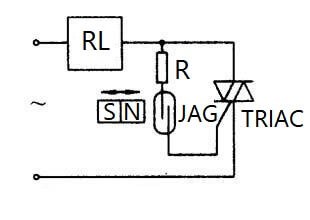
Figure 3. Proximity TRIAC Switch Circuit
Normally, JAG is disconnected and TRIAC is also turned off. Only when the small magnet moves closer, JAG pulls in to turn on the TRIAC and the load power supply. Since the current passing through the reed pipe is very small and the time is only a few microseconds, the life of the switch is very long.
Nowadays, the market for SCR applications is quite broad. SCR applications are found in the field of automatic control, electromechanical field, industrial electrical appliances, and household appliances.
The circuit of a zero-crossing trigger AC solid-state relay (AC-SSR) mainly includes the input circuit, photocoupler, zero-crossing trigger circuit, TRIAC switch circuit, protection circuit (RC absorption network). When the input signal VI (generally a high level) is added and the AC load power supply voltage passes through zero, the TRIAC is triggered to turn on the load power supply.
VII What is a TRIAC Dimmer?
1. TRIAC Dimmer Principle
At present, the mainstream non-energy-saving dimmers on the market are mostly TRIAC dimmers, which is also the most widely used dimmer at present.
Figure 4 is a schematic diagram of a typical TRIAC dimmer circuit. Connect R and C to become an RC circuit. When the power supply charges C, the TRIAC dimmer can be delayed to start until the voltage of C rises to the trigger point voltage of DIAC (usually 32 V). Adjusting the resistance of the potentiometer can change the start-up delay time, thereby changing the "on-time" of the TRIAC dimmer, that is, changing its "turn-on angle". Therefore, the average power supplied to the load can be changed.
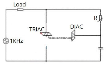
Figure 4. Schematic Diagram of TRIAC Dimmer Circuit
2. Difficulties in TRIAC Dimming
TRIAC needs 3 conditions to maintain conduction: trigger current IG, locking current IL, and holding current IH:
(1) IG is the condition for triggering TRIAC conduction.
(2) IL refers to the minimum current required for continuous conduction of NPNP in the process of NPNP amplification;
(3) After the TRIAC works normally if the current drop is too small, the TRIAC will be cut off, so the holding current is the minimum current required to maintain the conduction.
Recommended Articles:
Basic Understanding of Attenuators
Semiconductor Materials: Types, Properties and Production Process
 UTMEL
UTMEL
We are the professional distributor of electronic components, providing a large variety of products to save you a lot of time, effort, and cost with our efficient self-customized service. careful order preparation fast delivery service
1.What does a TRIAC do?
TRIACs are electronic components that are widely used in AC power control applications. They are able to switch high voltages and high levels of current, and over both parts of an AC waveform. This makes TRIAC circuits ideal for use in a variety of applications where power switching is needed.
2.What is TRIAC and its characteristics?
A TRIAC is defined as a three-terminal AC switch that is different from the other silicon-controlled rectifiers in the sense that it can conduct in both directions that is whether the applied gate signal is positive or negative, it will conduct. Thus, this device can be used for AC systems as a switch.
3.How do you identify a TRIAC terminal?
A multimeter can be used to test the health of a TRIAC. First, put the multimeter selector switch in a high resistance mode (say 100K), then connect the positive lead of the multimeter to the MT1 terminal of TRIAC and negative lead to the MT2 terminal of TRIAC (there is no problem if you reverse the connection).
4.Is a TRIAC a transistor?
A TRIAC is a small semiconductor device, similar to a diode or transistor. Like a transistor, a TRIAC is made up of different layers of semiconductor material. This includes N-type material, which has many free electrons, and P-type material, which has many "holes" where free electrons can go.
5.What is TRIAC output?
The TRIAC Output Module (TM) is a single normally open contact for 24 VAC loads only, 0.5 A. Ideal for switching 24 VAC control circuit loads found in packaged HVAC systems, and 24 VAC two-position or floating-point actuators. Sold in packages of 10.
6.Can I use a TRIAC to switch DC?
Yes, Can be used in the GATE terminal to trigger. But once triggered it will continue indefinitely switched on. So it has very limited applications on the dc field. Ultimately, The TRIAC is a three-terminal electronic device, which works as a switch for AC signals.
7.When the TRIAC is in the OFF state?
When the switch S is at position 1, the TRIAC is in forwarding blocking mode and hence the lamp remains in OFF state. If the switch is thrown into position 2, a small gate current flows through the gate terminal and hence the TRIAC is turned ON.
8.How do I turn off TRIAC?
You can turn off the TRIAC by short circuit TRIAC main terminals, connect a BJT in parallel to the TRIAC MT1 and MT2, just pulse the base of the BJT for a very short time to short the TRIAC then the TRIAC is off, remember if the current is very high use a power BJT.
9.How do I choose a TRIAC?
Select the TRIAC for the voltage of the line being used, the current through the load, and the type of load. Since the peak voltage of a 120 V ac line is 170 V, you would choose a 200 V (MIN) device. If the application is used in an electrically noisy industrial environment, a 400 V device should be used.
10.How does triac control AC motor speed?
The triac controls the flow of alternating current to the load, switching between the conduction state and the cut-off state, during the positive and negative half cycles of power supply (110/220 VAC that comes from the electric outlet of our homes).
 Modeling Wide Band-Gap Semiconductors for Enhanced PerformanceRakesh Kumar, Ph.D.31 January 20243571
The article delves into the challenges faced by silicon-based power electronic devices and highlights the potential of wide band-gap semiconductors. It also emphasizes the importance of modeling power semiconductor devices and provides insights into various models. For electrical energy conversion to be dependable and effective, power electronics and semiconductor device technologies are essential.
Read More Optimizing Energy Management with Non-Isolated DC-DC ConvertersRakesh Kumar, Ph.D.04 February 20243226
The article classifies DC-DC converters and discusses the benefits and limitations of them. It proposes a modified DC-DC converter topology that combines the Cuk and Positive Output Super Lift Luo topologies to achieve a higher voltage gain with fewer components.
Read More ‘6G Networks’ - Pioneering the Next Era of Connectivity And InnovationRakesh Kumar, Ph.D.18 March 20243573
The article provides a comprehensive overview of the evolving landscape of mobile networks, the requirements that will shape the future of mobile communication, and the innovative technologies driving the transition to 6G.
Read More Review of IoT-Based Smart Home Security Systems- Part 1Rakesh Kumar, Ph.D.28 March 20243979
The article discusses the evolution of IoT-based smart home security systems, integrating advanced technologies like Raspberry Pi, PIR sensors, and voice recognition for enhanced user experience and efficiency.
Read More Understanding Photodiodes: Working Principles and Applications - Part 2Rakesh Kumar, Ph.D.24 May 20245085
The article provides a comprehensive overview of photodiodes, focusing on their operational principles, key factors affecting their efficiency, advantages, and disadvantages, and highlights their diverse applications.
Read More
Subscribe to Utmel !
![35827]() 35827
35827Menda
![35823]() 35823
35823Menda
![A-1486]() A-1486
A-1486TE Connectivity
![D-108-11CS948]() D-108-11CS948
D-108-11CS948TE Connectivity
![620091-000]() 620091-000
620091-000TE Connectivity
![C07673N001]() C07673N001
C07673N001TE Connectivity
![880443-000]() 880443-000
880443-000TE Connectivity
![80110]() 80110
80110Brady Corporation
![80210]() 80210
80210Brady Corporation
![70325]() 70325
70325Brady Corporation
