Product
 Brand
Brand Articles
 Tools
Tools
What is a Digital Potentiometer?
Digital Potentiometer Control
2026 Executive Summary:
A Digital Potentiometer (DigiPOT) is a digitally controlled electronic component that mimics the function of a mechanical potentiometer, offering superior reliability, vibration resistance, and automation capabilities for modern circuits. This guide covers the operational principles, construction of programmable oscillators (using the AD5142), and a critical technical comparison between DigiPOTs and DACs for 2026 embedded system designs.
Catalog
Ⅰ What are the Key Features of Digital Potentiometers?
A Digital Potentiometer (DigiPOT) is a solid-state device that digitally adjusts resistance via communication protocols like I2C or SPI, offering precise, drift-free control for modern electronics. In 2026, these components are critical for automating calibration in IoT devices and industrial systems.
◆ High Precision & Stability: Produced according to advanced sensor principles, modern DigiPOTs offer exceptional linearity, accuracy, and temperature stability compared to mechanical predecessors.
◆ Software-Defined Control: Using firmware (C code or Python scripts) to realize functions allows for real-time customization according to changing user requirements without physical intervention.
◆ Non-Contact Longevity: The working method is solid-state (non-contact), completely avoiding the physical abrasion, contact bounce, and wear-and-tear of traditional potentiometers, resulting in a significantly longer lifespan and higher reliability.
◆ Blind-Spot Free Measurement: Since the mechanical brush substrate is eliminated, the effective electronic stroke reaches the equivalent of 360°, realizing no blind spot measurement and seamless resistance transitions.
◆ Versatile Signal Handling: Supports multiple output signal types (0-5V, 0-10V, 4-20mA loops, or serial digital signals), making them convenient for integration with modern 2026 microcontrollers (MCUs) and FPGA data acquisition systems.
◆ Programmable Calibration: The effective stroke and the output signal characteristics can be dynamically changed through software to meet various special requirements, such as logarithmic tapering for audio applications.
◆ Flexible Integration: Wide application range across automotive, medical, and consumer electronics sectors.
Ⅱ How Does a Digital Potentiometer Work?
The operating principle of a digital potentiometer is based on a resistive ladder network where CMOS switches utilize digital signals to select specific tap points, effectively replacing the mechanical wiper. It functions as a high-precision measuring instrument based on the principle of mutual compensation between the measured voltage and the known voltage. While traditional pots are mechanical, the digital potentiometer adopts a numerical control method to adjust the resistance value. This offers obvious advantages in 2026 designs: flexible usage, high adjustment accuracy, zero contact noise, resistance to vibration/shock, small footprint (IC packaging), and long operational life.
Digital potentiometers generally feature a standard bus interface (SPI, I2C, or Up/Down) and are programmed through a microcontroller or logic circuit. This makes them suitable to form a variety of programmable analog devices, such as programmable gain amplifiers (PGAs), programmable filters, programmable linear stabilized power supplies, and digital volume control circuits. It truly realizes the concept of "putting analog devices on the bus" (controlling analog function blocks via digital bus systems).
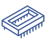
Structurally, the digital potentiometer belongs to the equivalent circuit of an integrated three-terminal variable resistance device. When used as a voltage divider, its high end, low end, and sliding (wiper) end are represented by VH, VL, and VW respectively. When used as a rheostat or adjustable resistor, they are represented by RH, RL, and RW.
Internal Architecture: The control section typically includes four digital modules: an up/down counter, a decoding circuit, a save/restore control circuit, and non-volatile memory (EEPROM). The counter drives the decoding circuit to control the switch array. When the external counting pulse stops or the chip selection signal becomes invalid, only one output terminal of the decoding circuit remains active, selecting a single MOS tube (Switch) to turn on, connecting the specific resistor step.
Memory Retention: A key feature for 2026 standards is non-volatile memory. When the circuit is powered on again after a failure, the digital potentiometer retrieves the saved control data, restoring the resistance value to the last known state. This ensures the user experience matches that of a mechanical potentiometer ("set and forget"). However, because internal switches operate in a "break-before-make" manner, slight transient resistance changes may occur during adjustment until the target value is reached.
Ⅲ How to Construct a Programmable Oscillator (Wien Bridge)
You can construct a highly stable programmable oscillator by replacing the mechanical resistors in a Wien Bridge circuit with a digital potentiometer (digiPOT) to dynamically control frequency and amplitude via software. While digiPOTs are often used for DC calibration, they are equally versatile for generating AC signals. In modern signal processing, the ability to adjust frequency via an MCU interface is invaluable. Below is a method to build a programmable oscillator where frequency and amplitude are independently adjustable.

Figure 1. Programmable Wien bridge oscillator with stable amplitude, utilizing AD5142 digiPOT for frequency control.
Figure 1 illustrates a diode-stabilized Wien bridge oscillator capable of generating accurate sine waves from approximately 10 kHz to 200 kHz at the output (VOUTPUT). The circuit consists of a band-pass filter and a voltage divider. This design utilizes the **ADA4610-1** rail-to-rail precision amplifier and the **AD5142 digiPOT**, which contains two independently controllable potentiometers with 256-step resolution. Resistance is programmed via SPI (see Figure 2), allowing for precise frequency tuning.
In this classic oscillator circuit, R1A, R1B, C1, and C2 form the positive feedback loop. R2A, R2B, and parallel diodes D1/D2 form the negative feedback loop. The oscillation frequency formula is:
![]()
For continuous oscillation, phase shift in the loop gain must be eliminated. The programmable resistance R on the AD5142 is defined by:

Where D is the decimal equivalent of the programmable digital code (0-255) and RAB is the total resistance of the potentiometer.

Figure 2. AD5142 Functional Block Diagram
Gain Stability: The gain ratio R2/R1 should be set slightly above 2 to ensure oscillation startup. The diodes in the negative feedback loop act as automatic gain control; as amplitude rises, diode resistance drops, reducing gain to stabilize the output. R2 can be used to tune the oscillation amplitude independent of frequency.
Performance Data: Using a 10 kΩ dual digiPOT, we can tune frequencies such as 8.8 kHz, 17.6 kHz, and 102 kHz with resistance settings of 8 kΩ, 4 kΩ, and 670 Ω respectively. The frequency error remains low (±3%) at lower frequencies but may increase to 6% at 200 kHz due to the bandwidth limitations of the digiPOT.
Technical Note: Ensure you do not exceed the bandwidth limit of the specific digital potentiometer model. For applications requiring simultaneous resistance changes to avoid transient states, use a daisy-chain capable digiPOT like the AD5204.
Ⅳ Digital Potentiometer vs. DAC: 2026 Comparison
The primary difference lies in the output structure: a Digital Potentiometer acts as a resistive element (three-terminal device), whereas a Digital-to-Analog Converter (DAC) acts as a voltage or current source (buffered output). Both use digital inputs to control analog outputs, but their optimal use cases in 2026 differ significantly.

Figure 3. (a) Digital Potentiometer structure vs. (b) DAC structure
Most digital potentiometers lack an output buffer, meaning they cannot drive low-impedance loads directly. In contrast, DACs typically include an internal operational amplifier to buffer the output.
Digital-to-Analog Converter (DAC)
DACs typically use a resistor string or R-2R ladder architecture. They are optimized for generating specific voltage or current levels.
Resolution: High-end DACs in 2026 offer 16-bit to 24-bit resolution, providing microvolt-level control (e.g., an 18-bit 2.5V DAC has an LSB of just 9.54μV). This is superior for high-precision industrial control (robotics, engines).
Speed: Parallel interface DACs are faster, suitable for signal generation. Serial DACs (SPI/I2C) are slower but cost-effective.
Drive Capability: Many DACs can source/sink significant current (e.g., 30mA) via internal buffers/amplifiers.
Density: DACs can be highly integrated (e.g., 32 channels on a single chip), whereas DigiPOTs rarely exceed 6 channels per package.
Digital Potentiometer (DigiPOT)
The DigiPOT functions as an adjustable resistor divider. It is unique because it allows the high-side voltage to vary, unlike a DAC which relies on a fixed reference.
Functionality: Can be configured as a voltage divider (3-terminal) or a variable resistor/rheostat (2-terminal).
Resolution: Generally lower than DACs, typically capping at 10-bit (1024 taps), though this is sufficient for calibration and volume control.
Voltage Flexibility: The terminals (H, L, W) can handle analog voltages within the supply rails, functioning effectively in feedback loops where a DAC cannot easily replace a resistor.
Selection Guide: Which should you choose?
Choose a DAC if: You need to generate a specific waveform, require high drive capability for a low-impedance load, or need ultra-high resolution (16-bit+).
Choose a Digital Potentiometer if: You are controlling an op-amp feedback network (gain control), need a variable resistor for analog filtering, require volume adjustment (logarithmic taper), or need to calibrate a sensor bridge.

Figure 4. Application Example: Both a DAC or a DigiPOT can technically control the dimming of the MAX1553 LED driver, but the implementation differs.
 UTMEL
UTMEL
We are the professional distributor of electronic components, providing a large variety of products to save you a lot of time, effort, and cost with our efficient self-customized service. careful order preparation fast delivery service
1.How does a digital potentiometer work?
A digital potentiometer (also known as digital resistor) has the same function as a normal potentiometer but instead of mechanical action it uses digital signals and switches. Only one switch is closed at the same time and in this way the closed switch determines the 'wiper' position and the resistance ratio.
2.Is a potentiometer analog or digital?
A potentiometer is a simple knob that provides a variable resistance, which we can read into the Arduino board as an analog value. In this example, that value controls the rate at which an LED blinks.
3.What are the different types of potentiometers?
There are two main types of potentiometer, linear potentiometers and rotary potentiometers. Membrane Potentiometers are another type of potentiometer they are often referred to as “soft pots” and can be either linear or rotary.
4.Where is potentiometer used?
Potentiometers are commonly used to control electrical devices such as volume controls on audio equipment. Potentiometers operated by a mechanism can be used as position transducers, for example, in a joystick.
5.What are the disadvantages of potentiometer?
*The major disadvantage is that it requires a large force to move their sliding contacts i.e. wiper. There is wear and tear due to movement of the wiper. It reduces the life of this transducer. *There is limited bandwidth. *There is inertial loading.
 What is Potentiometer?UTMEL25 October 20217957
Hello, I am Rose. Welcome back to the new post today. The potentiometer is a type of electromechanical component that can be found in a variety of instruments and electronic devices. A potentiometer is a resistance that can be adjusted and changed, and it is an electronic component that can be modified. This article mainly introduces structure, classification, electrical parameters and model name and type of potentiometer.
Read More What is a Digital Potentiometer?UTMEL08 January 20268671
Digital potentiometer, also known as CNC programmable resistor, is a new CMOS digital and analog mixed signal processing integrated circuit that replaces traditional mechanical potentiometer (analog potentiometer). The digital potentiometer is controlled by a digital input and produces an analog output. Depending on the digital potentiometer, the maximum tap current can range from a few hundred microamps to a few milliamperes.
Read More
Subscribe to Utmel !
![6GK59240PS001AA2]() 6GK59240PS001AA2
6GK59240PS001AA2Siemens
![AMEPR10-4224Z]() AMEPR10-4224Z
AMEPR10-4224Zaimtec
![AMER120-36340CAZ-NA]() AMER120-36340CAZ-NA
AMER120-36340CAZ-NAaimtec
![AMER120-24500CAZ-NA]() AMER120-24500CAZ-NA
AMER120-24500CAZ-NAaimtec
![LNE-24V150WACA]() LNE-24V150WACA
LNE-24V150WACADelta Electronics
![AMEPR16-4229Z]() AMEPR16-4229Z
AMEPR16-4229Zaimtec
![AMEPR50N-42115Z]() AMEPR50N-42115Z
AMEPR50N-42115Zaimtec
![AMER50-42105Z]() AMER50-42105Z
AMER50-42105Zaimtec
![AMEPR50N-42100Z]() AMEPR50N-42100Z
AMEPR50N-42100Zaimtec
![AMEPR60N-42140Z]() AMEPR60N-42140Z
AMEPR60N-42140Zaimtec