
 Product
 Brand
Brand Articles
 Tools
Tools
What is Band Pass Filter?
RC Band Pass Filters - How To Design The Circuit
Ⅰ. What is a Bandpass Filter?
A bandpass filter is defined as a circuit that permits a signal to flow between two frequencies. Some BPF band-pass filter designs can be made using external power supply and active components (such as integrated circuits and transistors), and these active components are referred to as active band-pass filters. Passive bandpass filters, on the other hand, utilize any sort of power supply and passive components such as capacitors and inductors.
Wireless transmitters and receivers can benefit from these filters. BPF can be used in the transmitter to reduce the output signal's bandwidth to the bare minimum and transmit data at a specified place and format. Similarly, in the receiver, the filter allows signals in a desirable frequency range to be processed while avoiding signals in undesirable frequency ranges. The receiver's signal-to-noise ratio (S/N) can be improved with BPF.

Bandpass Filter Circuit
The best example of a bandpass filter circuit is an RLC circuit, as shown below. The filter can also be designed by combining LPF and HPF. In BPF, Bandpass describes a process of filtering filters. It should be distinguished from the passband, which refers to the actual part of the affected spectrum. The pastoral bandpass filter has no gain or attenuation, so it is a completely horizontal passband. This will completely attenuate every frequency outside the passband.
Bandpass Filter Circuit
In truth, bandpass filters aren't perfect, and they won't entirely attenuate all frequencies except the one you want. There is a part outside the desired passband, but it is not discarded, especially when the frequency is attenuated. This is known as filter roll-off, and the attenuation is normally measured in decibels (dB) for each octave unless the frequency is ten times the frequency. Let the filter proceed to the proposed design because the filter design appears to establish the roll-off as thinly as possible. This is usually accomplished by consuming passband ripple; otherwise, stopband ripple is used.
The difference between higher and lower frequencies is known as the filter bandwidth. The cutoff frequency is determined by the shape factor, which is a bandwidth fraction derived with two different attenuation values. A form factor of 2:1 at 20/2 dB, for example, means that the bandwidth calculated in the 20 dB attenuation frequency range is doubled in the 2 dB attenuation frequency range. Optical BPF is commonly used in theaters for photography and lighting. Instead of flakes, these filters use the contour of a transparent colored film.
Ⅱ. Different Types of Bandpass Filters
Widebandpass filters and narrow bandpass filters are two types of bandpass filters that can be classified.
Wideband pass filter
Lower pass and high pass sections, which are generally separate circuits for simple design and action, can be combined to form a WBF or wideband pass filter (WBF).

Wideband Pass Filter
Many practical circuits are aware of it. A band-pass filter with a 20dB/decade can be produced by combining two sections, such as a first-order low-pass, and the high-pass element can be deleted. Similarly, a 40 dB/decade band-pass filter can be created by cascading two second-order filters, low-pass and high-pass filters (HPF). This means that the order of the low-pass and high-pass filters determines the order of the band-pass filter (BPF). Below is a graph of the bandpass filter curve.

Frequency Response of BPF
A first-order HPF can be used to make a 20 dB/decade bandpass filter (High Pass Filter). In the diagram below, the frequency response of a first-order LPF (low pass filter) is displayed.
Narrow bandpass filter
Narrow bandpass filters, in general, employ numerous feedbacks. The operational amplifier is used in this band-pass filter, as illustrated in the circuit diagram below. The following are the key characteristics of this filter.

Narrow Bandpass Filter
Because it has two feedback channels, this filter is also known as a multi-feedback filter.
Inverting mode is used with an operational amplifier.
This filter's frequency response is depicted in the diagram below.

Frequency Response of NBPF
The filter can be constructed for exact center frequency (FC) and bandwidth or center frequency and BW in general. The following relationships can be used to determine the components of this circuit. To make design calculations easier, each of the C1 and C2 capacitors can be used for C.
R1 = Q /2Π FC CAF
R2 = Q /2Π FC C (2Q2-AF)
R3 = Q /Π FC Ç
According to the above equation, Af represents the gain at the intermediate frequency, so Af = R3 / 2R1
However, Af should satisfy this statement Af <2Q2
The FC (center frequency) of multiple feedback filters can be changed to a new frequency FC without changing the bandwidth or gain. This can be achieved by changing R2 to R2'
R2'= R2 *( fc / fc )2
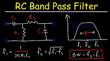
A passive bandpass filter is shown in the circuit below. We can calculate a passive bandpass filter using this circuit. The passive bandpass filter calculator's formula is presented below.

Passive Band Pass Filter Calculator
For low cutoff frequency = 1 /2ΠR2C2
For high cutoff frequency = 1 /2ΠR1C1
We may also calculate the BPF of an active inverting operational amplifier and the BPF of an active non-inverting operational amplifier.
Application of a bandpass filter
The following are some of the uses for bandpass filters.
Wireless transmitters and receivers frequently use these filters.
This filter can be used to improve the S/N (signal-to-noise ratio) and the receiver's empathy.
The major goal of the transmitter's filter is to keep the output signal's BW within the designated communication frequency band.
BPF is also commonly employed in optical equipment like lidar and lasers.
The ideal use of this filter is in audio signal processing when just a specified range of sound frequencies is required and the remainder is removed.
These filters are excellent for applications in sonar, instrumentation, medicine, and seismology.
These filters are used in communication systems to choose specific signals from a large number of signals.
As a result, this is everything about band-pass filter theory, covering the band-pass operation's circuit diagram, the various varieties of band-pass filters, and their applications. From the foregoing, we can deduce that astronomy is one of the other application areas for these filters and that these filters only allow a portion of the light spectrum to enter the device. These filters can be used to determine redshifts, find star tilts in the main series, and so forth.
 UTMEL
UTMEL
We are the professional distributor of electronic components, providing a large variety of products to save you a lot of time, effort, and cost with our efficient self-customized service. careful order preparation fast delivery service
1. How to determine whether it is a band pass filter or a band stop filter?
Bandpass allows useful signals in a certain frequency band to pass through, and band stop filters out signals in a certain frequency band, and the composition is the same, but the transmission direction is different.
2. What does the q value of a bandpass filter mean?
The ratio of the center frequency fo to the 3dB bandwidth BW of the passband: Q=fo/BW.
3. Is the range of the bandpass filter as small as possible?
The signal has a certain bandwidth, the passband range of the bandpass filter must be greater than or equal to this width to pass the signal, not as small as possible.
 What is a High-pass Filter?UTMEL10 March 202114457
A high-pass filter is a combination device of capacitors, inductances, and resistors that allow signal components above a certain frequency to pass, while greatly suppressing signal components below that frequency. The high-pass filter only attenuates the frequency components below a given frequency, and allows the frequency components above the cutoff frequency to pass, and there is no phase shift filtering process. Mainly used to eliminate low-frequency noise, also called low-cut filter.
Read More Introduction to Pi FilterUTMEL19 February 202115409
A Pi filter is a type of filter with a two-port, three-terminal block consisting of three elements with two terminals in each element: the first element is connected to the GND terminal via i/p, the second terminals are connected to the terminals from i/p to o/p and the third element is connected to the terminals from o/p to GND. The circuit model is going to be like a 'Pi' symbol. Capacitors and one inductor are the elements used in the circuit.
Read More EMI Filter: Introduction, Functions and ApplicationsUTMEL23 December 202013367
Electromagnetic interference filter, also known as "EMI filter" is an electronic circuit device used to suppress electromagnetic interference, especially noise in power lines or control signal lines. The EMI filter functions as two low-pass filters: one is to attenuate common mode interference, and the other is to attenuate differential mode interference. It is top choice for electronic equipment design engineers to control conducted electromagnetic interference and radiated electromagnetic interference.
Read More SAW Filter: Introduction, Features and ApplicationsUTMEL30 December 202010453
The Surface Acoustic Wave (SAW) filter is a passive band-pass filter made by using the piezoelectric effect and the physical characteristics of surface acoustic wave propagation. Its role is to filter and delay electrical signals. It has the advantages of small size, stable performance, strong overload capacity, low phase distortion, and no need to adjust, so it is used in televisions, video recorders, wireless data transmission systems and other fields.
Read More Introduction to Bandstop FilterUTMEL28 January 20219292
There are numerous filter types, including high-pass filters, low-pass filters, bandpass filters, and filters for bandstops. The high-pass filter only allows frequencies greater than the cut-off frequency, and the low-pass filter allows frequencies smaller than the cut-off frequencies. A specific band of frequencies will be permitted by the bandpass filter and a band stop filter will reject a specific band of frequencies. An overview of the bandstop filter is discussed in this article.
Read More
Subscribe to Utmel !
![ELJ-PA220KF]() ELJ-PA220KF
ELJ-PA220KFPanasonic Electronic Components
![LQM2MPN2R2NG0L]() LQM2MPN2R2NG0L
LQM2MPN2R2NG0LMurata Electronics
![LBMF1608T100K]() LBMF1608T100K
LBMF1608T100KTaiyo Yuden
![SDR0302-220ML]() SDR0302-220ML
SDR0302-220MLBourns Inc.
![SRN2512-1R0M]() SRN2512-1R0M
SRN2512-1R0MBourns Inc.
![LBC2518T6R8M]() LBC2518T6R8M
LBC2518T6R8MTaiyo Yuden
![ELJ-FC100JF]() ELJ-FC100JF
ELJ-FC100JFPanasonic Electronic Components
![VLS3015ET-3R3M]() VLS3015ET-3R3M
VLS3015ET-3R3MTDK Corporation
![PM5022-330M-RC]() PM5022-330M-RC
PM5022-330M-RCBourns Inc.
![IHLP2525AHER1R0M01]() IHLP2525AHER1R0M01
IHLP2525AHER1R0M01Vishay Dale


