
 Product
 Brand
Brand Articles
 Tools
Tools
Introduction to Bandstop Filter
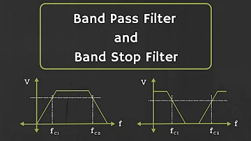
Band Pass Filter and Band Stop Filter Explained
Catalog
| I. General Introduction | 1. Working principle |
| 2. Different Bandstop Filters | |
| II. Applications | |
I. General Introduction
1. Working principle
When a low pass filter and a high pass filter are connected parallel to each other, the bandstop filter is created. The key purpose of the bandstop filter is to remove the same frequency band or to stop it. Some other names, such as band-reject or notch or band elimination filter, often apply to the bandstop filter. As discussed earlier, there will be one cut-off frequency for high pass filters, low pass filters also have one cut off frequency, but there are two cut off frequencies for this bandpass and bandstop filters.
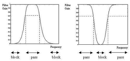
A specific spectrum of frequencies between the two cut off frequencies would be refused by this band stop filter. It enables frequencies above the high cut-off frequency and the low cut-off frequencies below. Based on the value of components used in the circuit design, these two cut off frequencies are calculated. It has a stopband and two passbands for this filter.

The figure above clearly shows the ideal features of the bandstop filter.
- ‘fL’= cut off frequency of low pass filter
- ‘fH’= cut off frequency of high pass filter
Bandpass and bandstop filter operations and characteristics are totally opposite to each other.
Band Stop Filter Theory
A low pass filter allows the low frequencies to pass through the circuit when an input is provided to the signal, and a high pass filter enables the high frequencies to pass through the circuit. The low-pass filter and the high-pass filter are connected simultaneously. When operating with the filter, there is some distinction between ideal and practical situations. This distinction is attributable to a capacitor's switching mechanism. In the figure above, the frequency response can be illustrated clearly.
2. Different Bandstop Filters
Band Stop Filter using R, L & C
Here, the inductor and capacitor are attached to the circuit resistor. The output is collected via the inductor and capacitor that are linked in sequence. The circuit, based on the frequency given at the input, will become a short or open circuit. For high frequency, the capacitor becomes a short circuit and the inductor is an open circuit and inductors operate as an open circuit for low frequencies, such as a short circuit and capacitor.
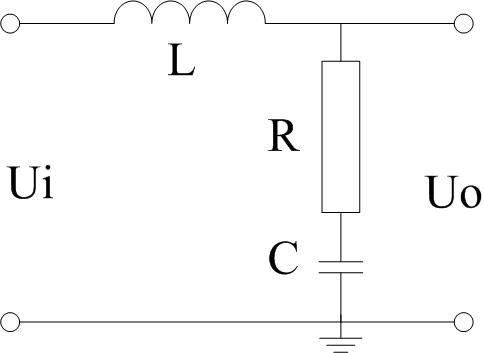
Because of this parallel relation between the capacitor and the inductor, we may assume that it becomes an open circuit at low and high frequencies, and at mid-range frequencies. It acts as a short circuit. So that's why the circuit does not allow mid-ranges and thus acts as a filter for band-reject.
Depending on the lower and greater cut off frequencies, the range of frequencies for which the filter serves as a short circuit. These cut-off frequencies depend on the parts used during the design and their value. The transfer function, according to the specification, specifies the component values.
Notch Filter
In Raman spectroscopy, live sound reproduction (public address systems or PA systems) and instrument amplifiers (particularly amplifiers or preamplifiers for acoustic instruments such as acoustic guitar, mandolin, bass instrument amplifiers, etc.), narrow notch filters (optical) are used to reduce or prevent audio feedback, while having little noticeable effect on the remainder of the frequency spectrum. Other names include 'band cap filter,' 'T-notch filter,' 'band-removal filter,' and 'band-reject filter.'
The filter for the narrow stop band is referred to as the filter NOTCH. This notch filter is used for the removal of a single frequency. Because of its two T formed networks, it is also called the twin T network. Maximal removal takes place at center frequency fC = 1/2πRC.
Inside the notch filter circuit, the capacitor and resistor are included. The capacitor value must be equal to or less than 1μF. By using the center frequency equation, the value of the resistor can be determined.
This notch filter is very useful for 50 or 60Hz single frequency removal.
By recording gain and frequency, the frequency response of the bandstop filter can be obtained.
Bandwidth is obtained through the lower and higher cut off frequencies. The stopband should have o0f zero again, and according to the ideal stopband filter, the passband should have an Amax gain.
II. Applications
The following are the applications of the band-stop filter:
- The bandstop filters are effectively used in electric guitar amplifiers. Guitar typically generates hum at 60Hz frequency. For amplifying the signal, the bandstop filter used is helpful in reducing the hum. The filter is not only used in this guitar, but also in acoustic applications such as base instrument amplifiers and mandolins.
- To minimize noise, a bandstop filter is used in image and signal processing.
- These bandstop filters are used for the reduction of static on a radio.
- The bandstop filter is used in applications in the medical field, such as biomedical noise reduction devices.
- These bandstop filters are used in DSL internet services and noise reducers to eliminate interference on the line.
- If noise occurs in the communication, the signal will be skewed, resulting in output errors. The bandstop filters are therefore used effectively to reduce these unnecessary harmonics and errors.
- In audio apps such as PA systems, i.e. This filter is used for Public Address Systems.
- These bandstop filters are used in optical communication technologies to remove distortions. Raman spectroscopy is one example of this.
This is all about a full view of the bandstop filter, therefore. It consists of one stopband and two passbands for this band stop filter. The features of bandpass filters and band stop filters are totally opposite. This filter is often referred to as a filter or notch filter for band rejection. In its growth, it used a low pass filter and a high pass filter. Both filters are linked to each other in parallel. It will have two frequencies of cut off, i.e. a low frequency of cut off and a high frequency cut. These intermediate frequencies are refused and all other frequencies are permitted.
 UTMEL
UTMEL
We are the professional distributor of electronic components, providing a large variety of products to save you a lot of time, effort, and cost with our efficient self-customized service. careful order preparation fast delivery service
How does a band stop filter work?
A band-stop filter works to screen out frequencies that are within a certain range, giving easy passage only to frequencies outside of that range. Also known as band-elimination, band-reject, or notch filters. Band-stop filters can be made by placing a low-pass filter in parallel with a high-pass filter.
What is a band stop filter used for?
The band stop filters are widely used in the electronics and communication circuit. They can be used to eliminate a band of unwanted frequencies while at the same time enabling other frequencies to pass with minimum loss.
Is band stop filter the same as notch filter?
In signal processing, a band-stop filter or band-rejection filter is a filter that passes most frequencies unaltered, but attenuates those in a specific range to very low levels. It is the opposite of a band-pass filter. A notch filter is a band-stop filter with a narrow stopband (high Q factor).
What is a notch filter in audio?
A notch filter decreases the amplitude of frequencies in the mid-range of the spectrum. It allows the low frequencies and the high frequencies to pass through. Audio engineers use this type of filter to cut out a problematic frequency. A notch filter can be implemented by modifying the low-pass filter effect.
What is band pass gain?
The gain of the filter is maximum at resonant or centre frequency and this is referred as total pass band gain. This pass band gain is denoted by 'Amax'. For low pass filter this pass band starts from 0 Hz and continues until it reaches the resonant frequency value at -3 dB down from a maximum pass band gain.
How is band pass calculated?
So all frequencies between the low cutoff frequecny and the high cutoff frequency are the passband of the bandpass filter. The gain of the circuit is determined by the formula, gain (AV)= -R2/R1. Thus, for example, to have a gain of 10, R2 must be 10 times the value of R1.
 What is a High-pass Filter?UTMEL10 March 202114457
A high-pass filter is a combination device of capacitors, inductances, and resistors that allow signal components above a certain frequency to pass, while greatly suppressing signal components below that frequency. The high-pass filter only attenuates the frequency components below a given frequency, and allows the frequency components above the cutoff frequency to pass, and there is no phase shift filtering process. Mainly used to eliminate low-frequency noise, also called low-cut filter.
Read More Introduction to Pi FilterUTMEL19 February 202115409
A Pi filter is a type of filter with a two-port, three-terminal block consisting of three elements with two terminals in each element: the first element is connected to the GND terminal via i/p, the second terminals are connected to the terminals from i/p to o/p and the third element is connected to the terminals from o/p to GND. The circuit model is going to be like a 'Pi' symbol. Capacitors and one inductor are the elements used in the circuit.
Read More EMI Filter: Introduction, Functions and ApplicationsUTMEL23 December 202013367
Electromagnetic interference filter, also known as "EMI filter" is an electronic circuit device used to suppress electromagnetic interference, especially noise in power lines or control signal lines. The EMI filter functions as two low-pass filters: one is to attenuate common mode interference, and the other is to attenuate differential mode interference. It is top choice for electronic equipment design engineers to control conducted electromagnetic interference and radiated electromagnetic interference.
Read More SAW Filter: Introduction, Features and ApplicationsUTMEL30 December 202010453
The Surface Acoustic Wave (SAW) filter is a passive band-pass filter made by using the piezoelectric effect and the physical characteristics of surface acoustic wave propagation. Its role is to filter and delay electrical signals. It has the advantages of small size, stable performance, strong overload capacity, low phase distortion, and no need to adjust, so it is used in televisions, video recorders, wireless data transmission systems and other fields.
Read More Introduction to Bandstop FilterUTMEL28 January 20219293
There are numerous filter types, including high-pass filters, low-pass filters, bandpass filters, and filters for bandstops. The high-pass filter only allows frequencies greater than the cut-off frequency, and the low-pass filter allows frequencies smaller than the cut-off frequencies. A specific band of frequencies will be permitted by the bandpass filter and a band stop filter will reject a specific band of frequencies. An overview of the bandstop filter is discussed in this article.
Read More
Subscribe to Utmel !
![ELJ-PA220KF]() ELJ-PA220KF
ELJ-PA220KFPanasonic Electronic Components
![LQM2MPN2R2NG0L]() LQM2MPN2R2NG0L
LQM2MPN2R2NG0LMurata Electronics
![LBMF1608T100K]() LBMF1608T100K
LBMF1608T100KTaiyo Yuden
![SDR0302-220ML]() SDR0302-220ML
SDR0302-220MLBourns Inc.
![SRN2512-1R0M]() SRN2512-1R0M
SRN2512-1R0MBourns Inc.
![LBC2518T6R8M]() LBC2518T6R8M
LBC2518T6R8MTaiyo Yuden
![ELJ-FC100JF]() ELJ-FC100JF
ELJ-FC100JFPanasonic Electronic Components
![VLS3015ET-3R3M]() VLS3015ET-3R3M
VLS3015ET-3R3MTDK Corporation
![PM5022-330M-RC]() PM5022-330M-RC
PM5022-330M-RCBourns Inc.
![IHLP2525AHER1R0M01]() IHLP2525AHER1R0M01
IHLP2525AHER1R0M01Vishay Dale


