
 Product
 Brand
Brand Articles
 Tools
Tools
Introduction to Pi Filter
Capacitor Input Π(Pi) Filter
Catalog
| I. General Introduction | |
| II. Features | 1. Characteristics |
| 2. Advantages and Disadvantages | |
| III. Applications | |
I. General Introduction
The electronic filter is a filter for signal processing and it is usable in the form of electrical circuits. A filter's main role is to allow the DC component of the filter load and to block the AC component of the rectifier output. The output of the filter circuit would therefore be a steady DC voltage. Using simple electronic components such as resistors, capacitors & inductors, the design of a filter circuit can be achieved. The inductor includes a feature that only makes DC signals as well as blocks of AC. Similarly, blocking the DC signals and providing AC signals is the property of the capacitor. Basically, the electronic filter removes from the signal that we have applied unnecessary frequency components and enhances needed ones such as active/passive, analog/digital, HPF, LPF, BPF, BSF, sampled/continuous-time, linear/non-linear, IIR/FIR, etc. There are some important filters, such as filters for inductors, filters for pi, filters for capacitors, and filters for LC.
A Pi filter is a type of filter with a two-port, three-terminal block consisting of three elements with two terminals in each element: the first element is connected to the GND terminal via i/p, the second terminals are connected to the terminals from i/p to o/p and the third element is connected to the terminals from o/p to GND. The circuit model is going to be like a 'π' symbol. Capacitors and one inductor are the elements used in the circuit.
To obtain a ripple-free DC voltage, the significance of a filter is Basically, when removing AC ripples from the o/p voltage of the rectifier, filters are effective. However, though removing ripples, the Pi filter is more effective because it requires an extra capacitor on the circuit's input area.
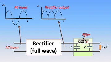
Below, the design of the pi filter circuit is shown. This circuit is built with two C1 and C2 filter capacitors and an 'L' choke. In the shape of the Greek letter pi, these three components are arranged. This is the reason the circuit is referred to as a pi filter. Here, C1 is linked across the rectifier's o/p;' L' is linked in series & 'C2' is linked across the load. Simply one segment of the filter is seen, but various equivalent parts are also used to advance the smoothing act.

A minor reactance against a.c. is given by the first filter capacitor (C1) O/p output rectifier variable, as it provides limitless reaction to the d.c. Ingredient. Thus, capacitor C1 avoids a large volume of a.c. Although the d.c. part The part keeps its journey to the choke 'L'
The choke (L) provides the d.c. with about zero reactance. Part and elevated reaction to a.c. Ingredient. It makes, thus, the d.c. Item to deliver via it, while the impartial a.c. It is possible to block the part.
The a.c. is avoided by the second filter capacitor (C2) The portion that the choke has not succeeded in stopping. Therefore, simply d.c. The part displays the load throughout.
II. Features
1. Characteristics
On small current drains, the features of the Pi filter are to generate a high o/p voltage. The key filtering act can be done in these filters through the capacitor on C1input. A second capacitor and inductor coil are filtered into the remaining AC ripples.
At the o/p of the filter, a high voltage can be reached when the entire input voltage is visible through the C1 capacitor input. The voltage drop is pretty slight around the C2 capacitor & choke coil.
Therefore, since it produces high voltage gain, this is the key advantage of the Pi capacitor. However, in addition to the high o/p voltage, the voltage control of the pi filter is exceptionally weak. This is due to the lowered output voltage due to the rise in current flow in the load.
The pi filter's voltage can be expressed as:
Vr = Idc/2fc
If C = C1 in the pi buffer, then the o/p voltage RMS value can be expressed as:
Vac rms = Vr / π√2
In the expression above, replace the value of 'Vr':
Vac rms = Vr / π√2 = 1 / π√2 * Idc/2fC1 = Idc Xc1√2
Here, Xc1 = 1/2 Ωc1 = 1/4 πfc1
The equation above is the reactance of the i/p capacitor at 2nd harmonic distortion.
The ripple voltage can be attained by multiplying Xc2/XL
Now V'ac rms = Vac rms Xc2/XL = Idc Xc1√2 * Xc2/XL
The ripple factor formula of the pi filter is:
γ = V'ac rms /Vdc
= Idc Xc1 Xc2 √2/Vdc XL
= Idc Xc1 Xc2 √2/Idc XL = Idc Xc1 Xc2√2/Idc RLXL
= Xc1 Xc2 √2/ RLXL
γ = √2/RL * 1/2 Ω c1* 1/2 Ω c2* 1/2 Ω L
= √2/8 Ω3 C1 C2LRL
2. Advantages and Disadvantages
The following are the advantages of the pi filter:
The output voltage is elevated,
The ripple factor is weak,
The peak inverse voltage (PIV) is elevated.
The disadvantage of pi filter include the following
The control of the voltage is bad.
Broad Dimensions
Weighty Weighty
Expensive Prices
III. Applications
The following are the applications of the pi filter.
The pi filter applications primarily provide communication devices for recovering the specific signal after modulation.
This filter is primarily used inside both signal and power lines to attenuate noise.
The signal can be converted into many high frequencies during the conversation. In comparison, these filters are used at the end of the receiver to demodulate the same frequency spectrum.
Power Converters
As already discussed, Pi filters are an excellent DC filter to suppress the AC ripples. Due to this behavior, Pi filters are extensively used in Power Electronic designs like AC-DC converter, Frequency converter, etc.
Pi filters are usually directly linked to the bridge rectifier and the output of the Pi filters is referred to as the High Voltage DC. For further operation, the output DC High Voltage is used for the power supply driver circuitry.
This design, from the bridge rectifier diode to the driver, has a distinct Pi-Filter operation. First, this Pi filter provides smooth DC for the overall driver circuit's ripple-free operation, resulting in a low output ripple from the power supply's final output, and the other is for isolating main lines across the driver circuit from the high switching frequency.
In a power supply where a Pi filter is an important component, a properly constructed line filter can provide common-mode filtration (a filter that rejects noise signal as if it were an independent single conductor) and differential mode filtration (differentiating two switching frequency noise, especially high-frequency noise that can be added to the mains line). A pi filter is also referred to as a Power Line filter if used in Power Electronics Application.
 UTMEL
UTMEL
We are the professional distributor of electronic components, providing a large variety of products to save you a lot of time, effort, and cost with our efficient self-customized service. careful order preparation fast delivery service
What does a pi filter do?
Pi filters are basically one inductor surrounded by two capacitors and arranged like the Greek letter Pi. The input capacitor is selected to offer low reactance and repel the majority of the nuisance frequencies or bands to block. Its inverse, the T filter uses two shunt inductors and a coupling capacitor.
How do you make a pi filter?
The designing of a filter circuit can be done using basic electronic components like resistors, capacitors & inductors. The inductor includes a property like it permits only DC signals as well as blocks AC. Similarly, the property of the capacitor is to block the DC signals and supply AC signals.
Why π filters are not suitable for varying loads?
Explain why π-filters are not suitable for varying loads? Voltage regulation in case of π-filters is very poor and, therefore, π-filters are not suitable for varying loads. 14. ... R-C filters have poor voltage regulation and need adequate ventilation to dissipate the heat developed in the resistor R.
Which filter is called as π type filter?
Definition: Pi filter consists of a shunt capacitor at the input side, and it is followed by an L-section filter. Thus, it is also called capacitor input filter. Significance of Capacitor input filter or Pi filter (π- filter) The ultimate aim of a filter is to achieve ripple free DC voltage.
 What is a High-pass Filter?UTMEL10 March 202114489
A high-pass filter is a combination device of capacitors, inductances, and resistors that allow signal components above a certain frequency to pass, while greatly suppressing signal components below that frequency. The high-pass filter only attenuates the frequency components below a given frequency, and allows the frequency components above the cutoff frequency to pass, and there is no phase shift filtering process. Mainly used to eliminate low-frequency noise, also called low-cut filter.
Read More Introduction to Pi FilterUTMEL19 February 202115445
A Pi filter is a type of filter with a two-port, three-terminal block consisting of three elements with two terminals in each element: the first element is connected to the GND terminal via i/p, the second terminals are connected to the terminals from i/p to o/p and the third element is connected to the terminals from o/p to GND. The circuit model is going to be like a 'Pi' symbol. Capacitors and one inductor are the elements used in the circuit.
Read More EMI Filter: Introduction, Functions and ApplicationsUTMEL23 December 202013383
Electromagnetic interference filter, also known as "EMI filter" is an electronic circuit device used to suppress electromagnetic interference, especially noise in power lines or control signal lines. The EMI filter functions as two low-pass filters: one is to attenuate common mode interference, and the other is to attenuate differential mode interference. It is top choice for electronic equipment design engineers to control conducted electromagnetic interference and radiated electromagnetic interference.
Read More SAW Filter: Introduction, Features and ApplicationsUTMEL30 December 202010483
The Surface Acoustic Wave (SAW) filter is a passive band-pass filter made by using the piezoelectric effect and the physical characteristics of surface acoustic wave propagation. Its role is to filter and delay electrical signals. It has the advantages of small size, stable performance, strong overload capacity, low phase distortion, and no need to adjust, so it is used in televisions, video recorders, wireless data transmission systems and other fields.
Read More Introduction to Bandstop FilterUTMEL28 January 20219337
There are numerous filter types, including high-pass filters, low-pass filters, bandpass filters, and filters for bandstops. The high-pass filter only allows frequencies greater than the cut-off frequency, and the low-pass filter allows frequencies smaller than the cut-off frequencies. A specific band of frequencies will be permitted by the bandpass filter and a band stop filter will reject a specific band of frequencies. An overview of the bandstop filter is discussed in this article.
Read More
Subscribe to Utmel !
![PA5175.153NLT]() PA5175.153NLT
PA5175.153NLTPulse
![HLQ02100HTTR]() HLQ02100HTTR
HLQ02100HTTRKYOCERA
![B66434GX197]() B66434GX197
B66434GX197TDK
![L06031R5CGWTR]() L06031R5CGWTR
L06031R5CGWTRKYOCERA
![MMBFJ309_Q]() MMBFJ309_Q
MMBFJ309_QON Semiconductor
![MAX2266EVKIT]() MAX2266EVKIT
MAX2266EVKITMaxim
![HM66-153R3LFTR7]() HM66-153R3LFTR7
HM66-153R3LFTR7TT Electronics
![PCDS105BMT120]() PCDS105BMT120
PCDS105BMT120Viking Tech
![PL8151]() PL8151
PL8151Pulse
![PCH-27-564L]() PCH-27-564L
PCH-27-564LCoilcraft
