
 Product
 Brand
Brand Articles
 Tools
Tools
EMI Filter: Introduction, Functions and Applications
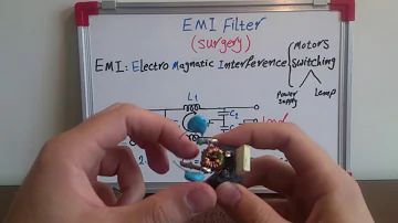
What's EMI (Electro Magnetic Interference) Filter? we open one of them to find out the answer
Catalog
| I. Introduction | 1.General Introduction |
| 2.Circuit | |
| 3.Why We Choose EMI Filters | |
| II. Functions | |
| III. Application | |
I. Introduction
1. General Introduction
What is a filter? Filters are devices that filter waves. Generally, there are two ports, one input signal, and one output signal. It can be said that it is an important electronic component. The filter transmits the power of the power supply to the equipment, which greatly attenuates the EMI electromagnetic interference signal transmitted through the power supply and protects the equipment from its harm; at the same time, it can effectively control the equipment itself. EMI signal prevents it from entering the grid, polluting the electromagnetic environment, and harming other equipment. In modern telecommunications equipment and various control systems, filters are widely used; among all electronic components, the most used and the most complicated technology is the filter. The quality of the filter directly determines the quality of the product. Therefore, the research and production of filters have always been paid attention to by all countries.
An electromagnetic interference filter, also known as "EMI filter" is an electronic circuit device used to suppress electromagnetic interference, especially noise in power lines or control signal lines.
The function of the electromagnetic interference filter is to keep the noise generated inside the electronic device from leaking out while preventing the noise generated by the AC line outside the electronic device from entering the device.
Electromagnetic interference filters are usually composed of a network of passive electronic components. These components include capacitors and inductors, which make up an LC circuit.
2. Circuit
The basic circuit of the electromagnetic interference filter is shown in the figure below.

The five-terminal device has two input terminals, two output terminals, and a ground terminal. The shell should be connected to the ground when in use. The circuit includes common mode choke (also known as common mode inductance) L and filter capacitors C1 to C4. L has no effect on series mode interference, but when common-mode interference occurs, because the magnetic flux direction of the two coils is the same, the total inductance increases rapidly after coupling, so it presents a large inductance to the common-mode signal, so It is not easy to pass, so it is called a common mode choke. Its two coils are respectively wound on a low-loss, high-permeability ferrite magnetic ring. When a current passes through, the magnetic fields on the two coils will strengthen each other. The inductance of L is related to the rated current I of the EMI filter, see Table 1. It needs to be pointed out that when the rated current is large, the wire diameter of the common mode choke should also be increased accordingly in order to be able to withstand a large current. In addition, an appropriate increase in inductance can improve low-frequency attenuation characteristics. C1 and C2 use film capacitors, the capacity range is roughly 0.01μF ~ 0.47μF, mainly used to filter series mode interference. C3 and C4 are connected across the output terminal, and the midpoint of the capacitor is grounded, which can effectively suppress common-mode interference. C3 and C4 can also be connected in parallel at the input end, and ceramic capacitors are still used, and the capacitance range is 2200pF~0.1μF. In order to reduce the leakage current, the capacitance should not exceed 0.1μF, and the midpoint of the capacitor should be connected to the earth. The withstand voltage values of C1~C4 are 630VDC or 250VAC.
3. Why We Choose EMI Filters
A magnetic interference filter is a special purpose filter, mainly used to filter electromagnetic interference on cables. It has several differences from filters used in general circuits:
The working frequency range is wide, from tens of KHZ to more than 1GHZ.
Generally, the impedance of the filter connected to the circuit is fixed, but the impedance of the circuit connected to the electromagnetic interference filter is not fixed, but changes with the frequency.
So why do we choose EMI filters?
The digital pulse circuit is the main source of electromagnetic interference. The pulse signal is rich in high-order harmonics, and these harmonics are not needed by us, and these high-order harmonics are easy to radiate and couple, which is a strong interference source. Therefore, an electromagnetic interference filter should be used to keep only the pulse signal of the useful working frequency (1/π*tr) and filter out other high-frequency harmonic signals.
High-frequency electromagnetic waves are more efficient in space transmission and easier to be absorbed, so the noise voltage and current they generate in the circuit are also high-frequency.
When there is a conduction current on the wire, the higher the current frequency, the easier it is to form radiation, which will cause stronger radiation disturbance.
There are distributed capacitance and mutual inductance between wires or cables, which will produce mutual crosstalk. These interferences are mainly high-frequency, and the higher the frequency, the more serious the crosstalk. The most effective method is to filter out the low-pass filter.
II. Functions
The role of interference filtering in electromagnetic compatibility design, most electronic product designers' understanding of interference filters is generally limited to: "Electronic products must pass the power line conduction emission test and power line immunity test, and must be used on the power line Interference filter". There is very little understanding of other functions of interference filters, which results in products often failing to pass other test items, such as radiated emission, radiated immunity, and conduction sensitivity tests on signal lines. In fact, electromagnetic interference filters are a very important type of device for smoothing most of the electromagnetic compatibility tests and ensuring the function of the product. Here are some circumstances where EMI filters can fix the problems:
1. The enclosure or cabinet shielding of the equipment is perfect, but it still produces excessive radiation emission:
The solution to this problem is to install a filter at the port of the cable to filter out the interference current.
2. The independent equipment does not have any electromagnetic interference problems (radiated emission and immunity are fully qualified), but when the necessary external cables are connected, interference problems occur:
The solution is to install a filter at the port of the cable to filter out the electromagnetic energy received by these conductors from the space before they reach the electronic circuit. On the other hand, prevent the interference energy in the electronic circuit from entering these conductors and then use the conductor to radiate.
3. When the electrical fast pulse is injected into the signal cable line, a fault occurs;
The frequency of electrical fast pulses is very high. These interferences are coupled into the cable through the capacitive coupling clamp and form interference currents on the cable. On the one hand, these currents directly flow into the circuit and cause interference to the circuit. On the other hand, they generate radiation and cause interference to the circuit. interference. The solution is to use shielded cables and install filters.
4.Can not pass the conduction sensitivity test on the cable bundle:
The purpose of the electrical fast transient pulse group immunity test is to verify the anti-interference ability of transient disturbances caused by lightning, ground faults, or switching inductive loads. This kind of test is a pulse group test composed of many fast transient pulses coupled to power lines, control lines, and signal lines. Naturally, it can also be solved by filtering at the cable port.
5.Cannot pass the electrostatic discharge test:
The impact of electrostatic discharge on the device circuit is largely due to the high-frequency electromagnetic fields surrounding the electrostatic discharge current. These electromagnetic fields are easily received by the wires and interfere with the circuit because of the high frequency. After installing the filter at the port of the cable, the problem was solved.
III. Applications
With the widespread application of switching power supplies, installing a filter at the entrance of the power cord has become a necessary measure. Because the switching power supply works in a high-power pulse state, it will generate strong electromagnetic radiation, which is induced to the line to form conduction emission. If the filter is not used, it is impossible to pass the electromagnetic compatibility test.
In the design, interference filters are often divided into power line interference filters and signal line interference filters. From the circuit point of view, these two types of filters are the same, they are both low-pass filters. The reason for this division is mainly because both have the greatest possible suppression of electromagnetic interference, and there are some differences. Special considerations. The signal filter must also consider that the filter cannot have a serious impact on the working signal and cannot cause signal distortion. In addition to ensuring that the power filter meets the safety requirements, it should also be noted that when the load current is large, the inductance in the circuit cannot be saturated.
The Application of Electromagnetic Interference Filter in Reforming RGB Display
Cables are the most important factor that causes electromagnetic compatibility problems in the system. This situation often occurs in electromagnetic compatibility tests: the equipment cannot pass the electromagnetic compatibility test no matter how improved, but the equipment can be smooth when the external cable of the equipment is removed Ground passes the test; in the actual use of electronic equipment, we often encounter such a situation: the equipment does not work normally or even often crashes, but after unplugging the connecting cable, everything is normal. In fact, most of the electromagnetic compatibility problems we encounter in reality are caused by cables, mainly including differential mode radiation generated by the signal current (differential mode current) loop and common-mode radiation generated by the common-mode current loop. Flat wire is also a kind of cable.
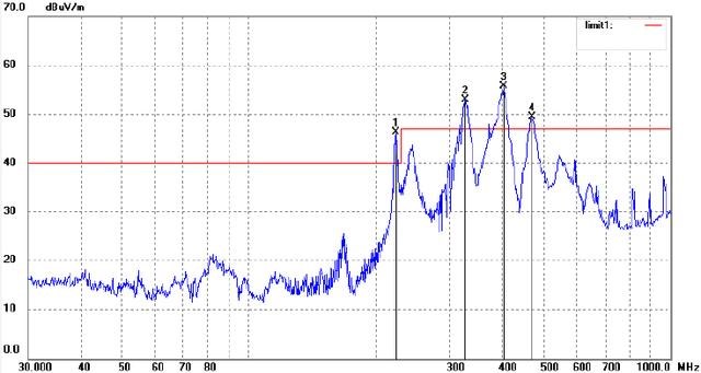
At present, RGB display screens are still widely used in industries where display requirements are not high. The following figure is a test chart of excessive radiation caused by higher harmonics of the screen clock (only the horizontal polarization direction exceeding the standard is listed).
After applying the EMI filter, the interface circuit and the cable are directly connected to the circuit. Whether the interface circuit has been effectively designed for EMC is directly related to whether the whole system can pass the EMC test. The interface circuit uses a low-pass filter to filter out the high-frequency common mode current on the cable is an effective way to reduce common-mode radiation.
The test data after using a low-pass filter in the interface circuit and processing the screen cable is as follows:
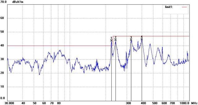
It can be seen from the test results that the four frequency points have decreased to varying degrees. Finally, the rectification is completed after processing the clock, cable, port, and backlight of the RGB mode display screen
 UTMEL
UTMEL
We are the professional distributor of electronic components, providing a large variety of products to save you a lot of time, effort, and cost with our efficient self-customized service. careful order preparation fast delivery service
What is an EMI filter used for?
Most electronics contains an EMI filter, either as a separate device, or embedded in circuit boards. Its function is to reduce high frequency electronic noise that may cause interference with other devices. Regulatory standards exist in most countries that limit the amount of noise that can emitted.
Where should I place my EMI filter?
For EMI compliance, install the filter as close to the point of power entry (POE) as possible. Bulkhead mount the filter to the chassis at the point of power entry with proper shielding, creating good input-output isolation.
What is the difference between RFI and EMI?
The terms EMI and RFI are often used interchangeably. EMI is actually any frequency of electrical noise, whereas RFI is a specific subset of electrical noise on the EMI spectrum.
 What is a High-pass Filter?UTMEL10 March 202114457
A high-pass filter is a combination device of capacitors, inductances, and resistors that allow signal components above a certain frequency to pass, while greatly suppressing signal components below that frequency. The high-pass filter only attenuates the frequency components below a given frequency, and allows the frequency components above the cutoff frequency to pass, and there is no phase shift filtering process. Mainly used to eliminate low-frequency noise, also called low-cut filter.
Read More Introduction to Pi FilterUTMEL19 February 202115409
A Pi filter is a type of filter with a two-port, three-terminal block consisting of three elements with two terminals in each element: the first element is connected to the GND terminal via i/p, the second terminals are connected to the terminals from i/p to o/p and the third element is connected to the terminals from o/p to GND. The circuit model is going to be like a 'Pi' symbol. Capacitors and one inductor are the elements used in the circuit.
Read More EMI Filter: Introduction, Functions and ApplicationsUTMEL23 December 202013367
Electromagnetic interference filter, also known as "EMI filter" is an electronic circuit device used to suppress electromagnetic interference, especially noise in power lines or control signal lines. The EMI filter functions as two low-pass filters: one is to attenuate common mode interference, and the other is to attenuate differential mode interference. It is top choice for electronic equipment design engineers to control conducted electromagnetic interference and radiated electromagnetic interference.
Read More SAW Filter: Introduction, Features and ApplicationsUTMEL30 December 202010453
The Surface Acoustic Wave (SAW) filter is a passive band-pass filter made by using the piezoelectric effect and the physical characteristics of surface acoustic wave propagation. Its role is to filter and delay electrical signals. It has the advantages of small size, stable performance, strong overload capacity, low phase distortion, and no need to adjust, so it is used in televisions, video recorders, wireless data transmission systems and other fields.
Read More Introduction to Bandstop FilterUTMEL28 January 20219292
There are numerous filter types, including high-pass filters, low-pass filters, bandpass filters, and filters for bandstops. The high-pass filter only allows frequencies greater than the cut-off frequency, and the low-pass filter allows frequencies smaller than the cut-off frequencies. A specific band of frequencies will be permitted by the bandpass filter and a band stop filter will reject a specific band of frequencies. An overview of the bandstop filter is discussed in this article.
Read More
Subscribe to Utmel !
![ELJ-PA220KF]() ELJ-PA220KF
ELJ-PA220KFPanasonic Electronic Components
![LQM2MPN2R2NG0L]() LQM2MPN2R2NG0L
LQM2MPN2R2NG0LMurata Electronics
![LBMF1608T100K]() LBMF1608T100K
LBMF1608T100KTaiyo Yuden
![SDR0302-220ML]() SDR0302-220ML
SDR0302-220MLBourns Inc.
![SRN2512-1R0M]() SRN2512-1R0M
SRN2512-1R0MBourns Inc.
![LBC2518T6R8M]() LBC2518T6R8M
LBC2518T6R8MTaiyo Yuden
![ELJ-FC100JF]() ELJ-FC100JF
ELJ-FC100JFPanasonic Electronic Components
![VLS3015ET-3R3M]() VLS3015ET-3R3M
VLS3015ET-3R3MTDK Corporation
![PM5022-330M-RC]() PM5022-330M-RC
PM5022-330M-RCBourns Inc.
![IHLP2525AHER1R0M01]() IHLP2525AHER1R0M01
IHLP2525AHER1R0M01Vishay Dale


