
 Product
 Brand
Brand Articles
 Tools
Tools
What is a High-pass Filter?

RC High Pass Filter Explained
Catalog
| I. Working Principle | |
| II. Types | 1. Active High-pass Filter |
| 2. Passive High-pass Filter | |
| 3. First-order high-pass filter and Second-order High-pass Filter | |
| III. Applications | |
I. Working Principle of a High-Pass Filter
The simplest high-pass filter is the "first-order high-pass filter". Its characteristics are generally expressed by a first-order linear differential equation. Its left side is exactly the same as the first-order low-pass filter. Only the right side is the derivative of the excitation source instead of The motivation source itself. When a lower frequency passes through the system, there is little or no output, and when a higher frequency passes through the system, there will be less attenuation.
In fact, for extremely high frequencies, a capacitor is equivalent to a "short circuit". These frequencies can basically be output at both ends of the resistor. In other words, this system is suitable for passing high frequencies but has a greater obstructive effect on low frequencies. It is the simplest "high pass filter".
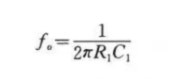
The working principle of this circuit is this: when the frequency is lower than f. When the signal of C1 is input to this filter, it is blocked due to the large capacitive reactance of C1, the output is reduced, and the lower the frequency, the smaller the output. When the frequency is higher than f. When the signal is input to this filter because the capacitive reactance of C1 is already small, it has no attenuation effect on the signal, so the filter has the function of letting high-frequency signals pass and blocking low-frequency signals. The corner frequency f of this circuit. Determined by the following formula:
In addition to components, high-pass filters can also be composed of LC.
Circuit of a High-pass Filter
The circuits of a high-pass filter and a low-pass filter are completely opposite, because the two components have been swapped, and the filter output signal is now taken out of the resistor
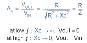
The low-level filter circuit only allows the signal to pass below its cut-off frequency point ƒc. As the name suggests, the passive high-pass filter circuit only passes the signal above the selected cut-off point, ƒc eliminates any low-frequency signals in the waveform. Consider the following circuit:

In this circuit, the reactance of the capacitor is very high at low frequencies, so the capacitor acts like an open circuit, blocking any input signal at VIN until the cutoff frequency point (reach ƒC). Above this cut-off frequency point, the reactance of the capacitor has been sufficiently reduced, and now it is more like a short circuit, allowing all input signals to pass directly to the output, as shown in the following filter response curve:

The frequency response curve of the passive high-pass filter is completely opposite to the frequency response curve of the low-pass filter. Here the signal is attenuated or attenuated at low frequencies, and the output increases by +20dB/Decade (6dB/Octave) until the frequency reaches the cutoff point (ƒc), again R=XC. Its response curve extends from infinity down to the cutoff frequency, and the output voltage amplitude 1/√2=70.7% of the input signal value>-3dB (20log(Vout/Vin)) input value.
We can also see the phase angle (φ) output signal LEADS input signal, and is equal to +45o at the frequency ƒc. The frequency response curve of this filter means that the filter can pass all signals to infinity. However, in practice, the filter response does not extend to infinity but is limited by the electrical characteristics of the components used.
The equation for the low-pass filter can be found using the same cutoff frequency point of the higher-order filter, but the equation for the phase shift is slightly modified to account for the positive phase angle, as shown below:

Circuit gain, Av is given in Vout/Vin (amplitude), and the calculation formula is as follows:
Calculate the cut-off point or "break point" frequency (ƒc) for a simple passive high-pass filter, consisting of an 82pF capacitor in series with a 240kΩ resistor:
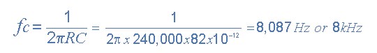
We can see that passive high-pass filters are the exact opposite of low-pass filters. The filter has no DC (0Hz) output voltage until the specified cutoff frequency (ƒc) point. The lower cut-off frequency point is 70.7% or -3dB (dB=-20logVOUT/VIN) allowable voltage gain.
The frequency range "below" the cutoff point ƒc is usually called the stopband and the frequency range above the cutoff point is usually called the passband.
The cutoff frequency, corner frequency, or -3dB point filter of the high pass can be found using the following standard formula: ƒc=1/(2πRC). The phase angle of the output signal obtained at ƒc is +45o. Generally, due to the higher operating frequency, the distortion of the high-pass filter is less than its equivalent low-pass filter.
The output voltage Vout depends on the time, as mentioned before, the constant and frequency of the input signal. By applying an AC sinusoidal signal to the circuit, it appears as a simple first-order high-pass filter. However, if we change the input signal to a "square wave" shaped signal with almost vertical step input, the response of the circuit will change significantly and produce a circuit commonly referred to as a differentiator.
II. Types of a High-Pass Filter
According to the different components used, active high-pass filters and passive high-pass filters can be classified.
1. Passive High-pass Filter
A filter composed of only passive components (R, L, and C). It is constructed using the principle that the reactance of capacitors and inductance components changes with frequency. The advantages of this type of filter are: the circuit is relatively simple, does not require a DC power supply, and has high reliability; the disadvantage is: the signal in the passband has energy loss, the load effect is more obvious, and the use of inductive components is likely to cause electromagnetic induction. When L is large, the size and weight of the filter are relatively large, which is not applicable in the low-frequency domain.
2. Active High-pass Filter
It is composed of passive components (usually R and C) and active components (such as integrated operational amplifiers). The advantages of this type of filter are: the signal in the passband not only has no energy loss, but also can be amplified, the load effect is not obvious, the mutual influence is small when multi-stage is connected, and the simple method of the cascade is easy to form a high-order filter. In addition, the filter is small in size, light in weight, and does not require magnetic shielding (because inductance components are not used); the disadvantage is that the passband range is limited by the bandwidth of active devices (such as integrated operational amplifiers) and requires DC power supply, which is reliable The performance is not as high as passive filters, and it is not suitable for high-voltage, high-frequency, and high-power applications.
3. According to the mathematical characteristics of the filter, it is divided into the first-order high-pass filter, second-order high-pass filter, etc.
Second-order High-pass Filter
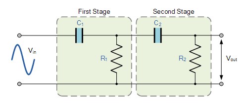
The above circuit uses two first-order filters connected or cascaded together to form a second-order or two high-pass network. Then, by simply using an additional RC network, the first-order filter stage can be converted to a second-order type, the same as the 2nd-order low-pass filter. The resulting slope of the second-order high-pass filter circuit is 40dB/decade (12dB/octave).
Like the low-pass filter, the cut-off frequency ƒc is determined by the resistance and capacitance as follows:
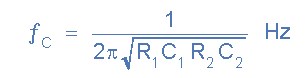
In practice, cascaded passive filters produce together because the dynamic impedance of each filter order affects its adjacent network, so it is difficult to accurately implement a larger order filter. However, in order to reduce the load effect, we can set the impedance of each subsequent stage to 10 times that of the previous stage, so R2=10*R1 and C2=1/10 of C1.
III. Applications of a High-Pass Filter
A very common application of this passive filter is in audio amplifiers as a coupling capacitor between two audio amplifier stages and speaker systems to guide higher frequency signals to smaller "tweeter" type speakers. It also blocks lower bass signals or is also used as a filter to reduce any low-frequency noise or "rumble"-type distortion. When used in audio applications, high-pass filters are sometimes referred to as "low cut" or "bass switching" filters.
In the power system, a high-pass filter is used to filter out the harmonics of a certain order and above in the harmonic compensation. Low-pass filters are used to drive subwoofers and other types of loudspeakers and block tweeters that they cannot effectively propagate. The high-pass filter can direct high-frequency sounds to a dedicated tweeter and block bass signals that may interfere with or damage the speakers. A low-pass filter that uses a coil instead of a capacitor can also direct low-frequency signals to the woofer at the same time. See audio crossover.
High-pass and low-pass filters are also used in digital image processing to transform in the frequency domain.
 UTMEL
UTMEL
We are the professional distributor of electronic components, providing a large variety of products to save you a lot of time, effort, and cost with our efficient self-customized service. careful order preparation fast delivery service
What is a high pass filter used for?
A high-pass filter effectively cuts out the frequency response of a mic below a certain set point, allowing only the frequencies above this point to “pass” through as the audio signal. High-pass filters remove unwanted and excess low-end energy that otherwise degrades the audio signal.
What does a high pass filter do to an image?
A high-pass filter can be used to make an image appear sharper. These filters emphasize fine details in the image – exactly the opposite of the low-pass filter.
What is the difference between low-pass filter and high pass filter?
A high-pass filter (HPF) attenuates content below a cutoff frequency, allowing higher frequencies to pass through the filter. A low-pass filter (LPF) attenuates content above a cutoff frequency, allowing lower frequencies to pass through the filter.
What is the bandwidth of high pass filter?
If we apply the low-pass-filter logic to a high-pass response, the band extends from the –3dB frequency to infinity.
 What is a High-pass Filter?UTMEL10 March 202114473
A high-pass filter is a combination device of capacitors, inductances, and resistors that allow signal components above a certain frequency to pass, while greatly suppressing signal components below that frequency. The high-pass filter only attenuates the frequency components below a given frequency, and allows the frequency components above the cutoff frequency to pass, and there is no phase shift filtering process. Mainly used to eliminate low-frequency noise, also called low-cut filter.
Read More Introduction to Pi FilterUTMEL19 February 202115422
A Pi filter is a type of filter with a two-port, three-terminal block consisting of three elements with two terminals in each element: the first element is connected to the GND terminal via i/p, the second terminals are connected to the terminals from i/p to o/p and the third element is connected to the terminals from o/p to GND. The circuit model is going to be like a 'Pi' symbol. Capacitors and one inductor are the elements used in the circuit.
Read More EMI Filter: Introduction, Functions and ApplicationsUTMEL23 December 202013370
Electromagnetic interference filter, also known as "EMI filter" is an electronic circuit device used to suppress electromagnetic interference, especially noise in power lines or control signal lines. The EMI filter functions as two low-pass filters: one is to attenuate common mode interference, and the other is to attenuate differential mode interference. It is top choice for electronic equipment design engineers to control conducted electromagnetic interference and radiated electromagnetic interference.
Read More SAW Filter: Introduction, Features and ApplicationsUTMEL30 December 202010464
The Surface Acoustic Wave (SAW) filter is a passive band-pass filter made by using the piezoelectric effect and the physical characteristics of surface acoustic wave propagation. Its role is to filter and delay electrical signals. It has the advantages of small size, stable performance, strong overload capacity, low phase distortion, and no need to adjust, so it is used in televisions, video recorders, wireless data transmission systems and other fields.
Read More Introduction to Bandstop FilterUTMEL28 January 20219305
There are numerous filter types, including high-pass filters, low-pass filters, bandpass filters, and filters for bandstops. The high-pass filter only allows frequencies greater than the cut-off frequency, and the low-pass filter allows frequencies smaller than the cut-off frequencies. A specific band of frequencies will be permitted by the bandpass filter and a band stop filter will reject a specific band of frequencies. An overview of the bandstop filter is discussed in this article.
Read More
Subscribe to Utmel !
![IHLP4040DZER6R8M01]() IHLP4040DZER6R8M01
IHLP4040DZER6R8M01Vishay Dale
![MLZ2012M2R2HT000]() MLZ2012M2R2HT000
MLZ2012M2R2HT000TDK Corporation
![NR6028T4R7M]() NR6028T4R7M
NR6028T4R7MTaiyo Yuden
![CLF7045NIT-100M-D]() CLF7045NIT-100M-D
CLF7045NIT-100M-DTDK Corporation
![MLF2012E120KT000]() MLF2012E120KT000
MLF2012E120KT000TDK Corporation
![CDRH104RNP-330NC]() CDRH104RNP-330NC
CDRH104RNP-330NCSumida America Components Inc.
![SRR1280-471K]() SRR1280-471K
SRR1280-471KBourns Inc.
![CM453232-6R8KL]() CM453232-6R8KL
CM453232-6R8KLBourns Inc.
![SRN3015-4R7M]() SRN3015-4R7M
SRN3015-4R7MBourns Inc.
![SLF7045T-102MR14-PF]() SLF7045T-102MR14-PF
SLF7045T-102MR14-PFTDK Corporation


