Product
 Brand
Brand Articles
 Tools
Tools
What is a Voltage Controlled Oscillator?

Voltage Controlled Oscillator (VCO) Explained
Executive Summary: Voltage Controlled Oscillators in 2026
What is a VCO? A Voltage Controlled Oscillator (VCO) is a critical electronic circuit that controls oscillation frequency based on an input voltage signal. It serves as the heartbeat of modern RF architecture.
Key Takeaways:
Core Function: Converts voltage input into frequency output with high precision.
2026 Relevance: Essential for 5G/6G telecommunications, IoT synchronization, and automotive radar systems.
Types: Includes LC (inductance-capacitance), RC (resistance-capacitance), and Crystal (Quartz) variants.
Catalog
Ⅰ What are the Characteristics of a VCO?
The defining characteristic of a voltage-controlled oscillator (VCO) is the linear relationship between its input control voltage (Uc) and the output angular frequency (ω0). In advanced 2026 electronic design, this linearity is crucial for signal integrity.
Key Technical Parameters:
Free Oscillation Frequency (ω0,0): The output frequency when the input voltage is zero.
Control Sensitivity (K0): The slope of the curve, representing how much the frequency changes per volt of input.
Linearity: In modern communications (5G/6G), the VCO serves as a frequency modulator. In Phase-Locked Loops (PLL), the input voltage acts as the error signal, making the VCO the controlled element that corrects phase drift.
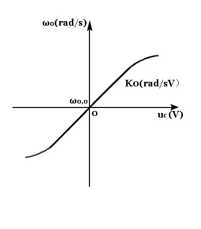
Figure 1: Control characteristics showing linearity in a Voltage Controlled Oscillator
VCOs are categorized into three primary architectures based on their frequency stabilization method:
Crystal VCO (VCXO): Highest frequency stability, narrow tuning range. Used in precision timing.
RC VCO: Lower stability, wide frequency range. Common in low-frequency integrated circuits.
LC VCO: Balanced performance. widely used in RF applications.
1. LC Voltage Controlled Oscillator
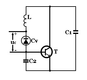
Principle circuit of LC voltage controlled oscillator
The LC VCO remains the standard for Radio Frequency (RF) generation. It functions by inserting a varactor diode (variable capacitance diode) into the oscillation tank circuit. In the schematic above:
T: Transistor (Active element).
L: Loop Inductance.
Cv: Varactor Diode (Capacitance changes with reverse-bias voltage).
As the control voltage (uc) changes, the capacitance (Cv) shifts, altering the resonant frequency based on the formula:
![]()
Formula: Relationship between VCO output frequency and control voltage
2. RC Voltage Controlled Oscillator
RC voltage-controlled multivibrators are typically found in monolithic integrated circuits where high precision is less critical than cost and size. They rely on the charging and discharging rates of capacitors through resistors to determine frequency.
3. Crystal Voltage Controlled Oscillator (VCXO)
For applications requiring ultra-low phase noise (such as 5G base stations), a varactor diode is connected in series with a quartz crystal. While standard crystals have a fixed frequency, adding voltage control allows for minor adjustments (pullability) to synchronize with external reference signals.
2026 Trend Update: Modern Deep-space communications and 6G research now utilize MEMS-based oscillators and advanced VCXOs to resolve the conflict between frequency stability and modulation range, pushing internal noise levels lower than ever before.
Ⅱ How Does a Voltage Controlled Oscillator Function?
A VCO functions by translating a DC voltage input into a corresponding AC frequency output. The mechanism varies by frequency band:
High-Frequency Control (Varactor Method)
In high-frequency RF circuits, the control voltage adjusts the depletion region width of a varactor diode.
Increased Reverse Bias: Widens the depletion region → Decreases Capacitance → Increases Frequency.
Decreased Reverse Bias: Narrows the depletion region → Increases Capacitance → Decreases Frequency.
Low-Frequency Control (Integrator Method)
For lower frequencies, we often use an operational amplifier approach. The oscillation frequency is proportional to the input voltage (Ui), creating a waveform based on charging/discharging cycles.

Circuit Analysis:
A1 (Integrator): Controls the rate of voltage change based on input.
A2 (Hysteresis Comparator): Acts as a switch. When output reaches +UZ, diode D cuts off, charging Capacitor C.
Cycle: When voltage drops, the comparator flips, discharging C rapidly. This cycle repeats, generating a sawtooth or square wave where frequency scales linearly with input voltage.
Ⅲ Modern Applications (2026 Industry Standards)
In 2026, VCOs are ubiquitous in both consumer electronics and industrial infrastructure. Common applications include:
Signal Generators: Creating precise waveforms for testing equipment.
Electronic Music Synthesizers: Generating variable tones and pitch modulation.
Phase-Locked Loops (PLL): Critical for clock generation in CPUs and communication data recovery.
Frequency Synthesizers: Used in 5G smartphones and Wi-Fi 7 routers.
Case Study: Electronic Tuning in Receivers
While modern devices use digital synthesis, the foundational principle is best understood through the classic VHF tuner circuit (shown below). By changing the control voltage (VC) between 0.5V and 30V, the circuit adjusts the varactor's junction capacitance, tuning the oscillation frequency between 170-220MHz. This "Electronic Tuning" eliminates the need for bulky mechanical variable capacitors.
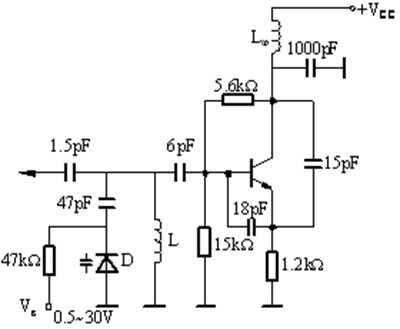
Classic Example: TV receiver VHF local oscillator circuit diagram
Ⅳ Tutorial: Building a VCO with a 555 Timer
Method 1: Using a JFET for Duty Cycle Adjustment
For hobbyists and students, the 555 timer offers an accessible way to build a VCO. In this configuration, a Field Effect Transistor (JFET) acts as a voltage-controlled resistor.

How it works:
The JFET (VT) is placed between the discharge and threshold pins.
By changing the Gate-Source voltage (VGs), you alter the drain-source resistance.
This changes the charging time constant of the multivibrator, effectively altering the frequency and duty cycle.
Note: Coupling capacitors C1 and C2 should be roughly 10x larger than the timing capacitor C3 to ensure stability.
Method 2: Direct Control Pin (Pin 5) Manipulation
The 555 timer has a specific "Control Voltage" pin (Pin 5). Internally, this pin is connected to a voltage divider providing a reference of 2/3 Vcc.

By applying an external voltage to Pin 5 (via a potentiometer or signal source), you override the internal reference. This modifies the threshold at which the capacitor charges and discharges, directly modulating the output frequency.
Ⅴ What is the Role of VCO in a PLL?
A Phase-Locked Loop (PLL) is a feedback control system that synchronizes an internal oscillator with an external signal. The VCO is the "muscle" of this system, while the Phase Detector is the "brain."
The PLL Workflow:
Phase Detector (PD): Compares the external input signal against the VCO's output.
Error Generation: If the phases/frequencies do not match, an error voltage is generated.
Loop Filter (LF): Smooths this error voltage into a clean control signal (uC).
VCO Correction: The VCO receives this control voltage and adjusts its frequency until it matches (locks onto) the input.
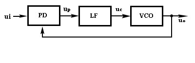
Block Diagram: How a VCO fits into a Phase-Locked Loop
In 2026 digital systems, this mechanism is vital for "cleaning" jittery clock signals and multiplying frequencies for high-speed processors.
 UTMEL
UTMEL
We are the professional distributor of electronic components, providing a large variety of products to save you a lot of time, effort, and cost with our efficient self-customized service. careful order preparation fast delivery service
1 What is the output of VCO?
Voltage controlled oscillators are commonly abbreviated as VCO. The VCO's are electrical circuits that yield an oscillatory output voltage. A VCO is an oscillator which output frequency is proportional to the applied input voltage. VCO's often utilize a variable control voltage input to produce a frequency output.
2 What design parameters are observed in designing a voltage controlled oscillator?
Preferred requirements in the design of many VCOs are: 1) high spectral purity and low phase noise, 2) large frequency tuning range, 3) good frequency stability to the temperature and process, 4) low power consumption, 5) low fabrication cost, and 6) linearity of frequency versus control voltage for some applications.
3 What is the function of VCO in PLL?
A PLL is a feedback system that includes a VCO, phase detector, and low pass filter within its loop. Its purpose is to force the VCO to replicate and track the frequency and phase at the input when in the lock. The PLL is a control system allowing one oscillator to track with another.
4 How do you use a voltage controlled oscillator?
The applied input voltage determines the instantaneous oscillation frequency. Consequently, a VCO can be used for frequency modulation (FM) or phase modulation (PM) by applying a modulating signal to the control input. A VCO is also an integral part of a phase-locked loop.
 A Simple Method to Build a Programmable OscillatorUTMEL27 May 20227192
Hello, this is Candy. Nice to meet you. Digital potentiometers (digiPOT) are versatile and can be used for a variety of tasks, including filtering and generating AC signals. However, depending on the application, the frequency must occasionally be able to fluctuate and be altered. Programmable solutions that permit frequency change through the appropriate interface are quite handy and, in some situations, extremely beneficial to the development of such designs. Using digiPOT, this article shows how to make a programmable oscillator in which the oscillation frequency and amplitude may be modified independently of one another.
Read More Introduction to Types of Oscillator CircuitsUTMEL14 January 202616945
The oscillator operates on the theory of the oscillation and it is a mechanical or electronic unit. The periodic difference between the two items is dependent on the variations in the electricity. The oscillations are used in the watches, clocks, metal detectors and in many other applications use the oscillators.
Read More What are Resonators?UTMEL07 January 202617412
A resonator is an electronic component that can generate a resonant frequency. It has the characteristics of stability and good anti-interference performance. Like the low-frequency circuit, the resonator is also the basic component of the radio frequency circuit. It is widely used in filters, oscillators, frequency meters and adjustable In circuits such as amplifiers. The commonly used RF/MW resonators are basically transmission line resonators.
Read More How to Understand the Oscilloscope Bandwidth?UTMEL13 December 202110710
When a user selects an oscilloscope for essential measurements, the oscilloscope's key characteristics are frequently the only criteria used to determine which oscilloscope to employ. An oscilloscope's most essential index parameters are:Bandwidth, Sampling Rate, Record length
Read More Active Electroacoustic Resonator-Silent SpeakerUTMEL10 November 20215687
Hello everyone, I am Rose. Today I will introduce active electroacoustic resonator to you. The only component of this system is a closed-box dynamic speaker. The surface acoustic impedance of the diaphragm is appropriately changed by connecting an active electrical control system to generate an independently tunable sound absorption coefficient, bandwidth, and resonance frequency.
Read More
Subscribe to Utmel !
![RS30111-0415-C0-P0-A503]() RS30111-0415-C0-P0-A503
RS30111-0415-C0-P0-A503ALPS ALPINE
![EAAY05SLAYYA0]() EAAY05SLAYYA0
EAAY05SLAYYA0Everlight Electronics
![53AEA-C28-A18L]() 53AEA-C28-A18L
53AEA-C28-A18LBourns
![92Z2D-C24-EA0/289L]() 92Z2D-C24-EA0/289L
92Z2D-C24-EA0/289LBourns
![82A1A-B28-H25L]() 82A1A-B28-H25L
82A1A-B28-H25LBourns
![287T420S103A11]()
![287T364R105A21]()
![287T520S504A11]()
![287T328S105A11]()
![287T364R503A11]()