How to Understand the Oscilloscope Bandwidth?
Understanding Bandwidth - The #1 Test Gear Spec You Need to Know
Ⅰ. Bandwidth-what can this indicator tell us?
The analog bandwidth is a metric that can be used to determine the quality of a signal. When the amplitude of the real sine wave signal is 3dB, the amplitude of the sine wave measured by the oscilloscope is not lower than the highest frequency (see IEEE-1057). An ideal oscilloscope bandwidth and amplitude measurement error curve is shown in Figure 1. The amplitude measurement error is roughly 30% when the frequency of the sine wave under test is equal to the bandwidth of the oscilloscope (the response of the oscilloscope's amplifier is a first-order Gaussian), as shown in Figure 1.
The frequency of the sine wave to be measured must be substantially lower than the oscilloscope's bandwidth if you wish to measure the amplitude error of the sine wave is only 3%. (about 0.3 times the bandwidth of the oscilloscope). The basic rule for measuring signals with an oscilloscope is that the bandwidth of the oscilloscope is 5 times the frequency of the signal under examination, because most signals are far more complicated than sine waves.

Ⅱ. Bandwidth-what can't you tell us?
An oscilloscope is typically used to show and quantify complex electrical and optical signals, as well as to view the oscilloscope's amplitude versus time display. The frequency domain, not the time domain, should be used to describe analog bandwidth, which is a key indicator of an oscilloscope.
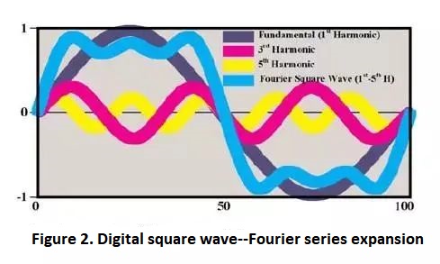
A complex signal, according to sampling theory, has a lot of spectrum components in the frequency domain (including harmonic components of multiple sine waves), as seen in Figure 2. The frequency components of the sampled signal can be seen via spectrum analysis. If you want to go all out, though, It is important to have the precise amplitude and phase information of each component of the complex signal in order to define the characteristics of these frequency components.
In this scenario, bandwidth can only help us figure out how to get these details. In terms of bandwidth measurement, we only know that if a sine wave of the same frequency and bandwidth is input, the oscilloscope's amplitude measurement error is 30%.
Ⅲ. What's the connection between bandwidth and time to rise?
Most engineers are interested in time measurement, such as the rise and fall times of a square wave, in addition to basic signal analysis. As a result, we can use the following formula to calculate the oscilloscope system's rise time based on the chosen bandwidth: tr = 0.35/BW (or 0.42/BW); more specifically:
BW =0.35/tr (or 0.42/tr)=5*Fclock (for conventional signals, tr=7% *T, where T=1/Fclock). The actual signal's bandwidth is defined as the harmonic frequency at which the signal's harmonic amplitude is 70% of the 0th wave (fundamental wave) (that is, a drop of 3dB).
The scale factor between the oscilloscope's bandwidth and the rising time is 0.35. (10 percent -90 percent rise time in the first-order Gaussian model). The response model of the first-order Gaussian RC low-pass filter is used by the majority of oscilloscope amplifiers. Although it is simple to use this method to compute tr rising time, this is not always the case in practice.
The table in Figure 3 shows how to determine the system bandwidth required by various signal standards. The recommended system bandwidth can assure adequate rising time or other measurement precision. The accuracy of the rise time results in the oscilloscope test will be influenced by a number of parameters in the instrument system. Signal source, probe, and oscilloscope are among these elements.
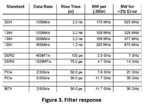
The table in Figure 3 implies that the signal and the oscilloscope test equipment have first-order response characteristics, but this is far from the case in reality, especially with today's high-speed serial transmissions. The correlation coefficient between the oscilloscope bandwidth and the rising time is close to 0.45 for the maximum flat envelope delay response. The rising time and bandwidth ratio coefficients have altered in Figure 3, as has the 20GHz amplitude-frequency response model, which has gone from a basic first-order to a 32-order response. The response characteristics of current high-performance oscilloscopes are similar to the 16-order and 32-order replies. This type of high-performance oscilloscope has a tr/BW scale factor of around 0.4 or 0.45. The oscilloscope's amplitude-frequency response is very flat from low frequency to the cut-off frequency of the oscilloscope bandwidth for such a scale factor.
Furthermore, if the instrument employs a high-quality filter, its amplitude and phase will be better corrected, allowing it to collect and analyze complicated signals with the highest level of fidelity. In the genuine sense, what is the best oscilloscope? Different rise times, amplitude-frequency responses, and phase responses can be found in two oscilloscopes with the same bandwidth performance. As a result, simply knowing the oscilloscope's bandwidth will not provide a reliable indication of its measurement capabilities or capacity to effectively record complicated signals (like high-speed serial data streams).
At the same time, whether the real rise time of the oscilloscope and the rise time result estimated from the oscilloscope's bandwidth are consistent is debatable. The only reliable way to determine an oscilloscope's true rise and fall times is to use an ideal step signal with a much faster rise time than the oscilloscope's.
Ⅳ. Probe bandwidth and rise time
1. Bandwidth
The probe bandwidth must be large in order to meet the design requirements of oscilloscope probes. A 100MHz oscilloscope probe, for example, requires that the measured frequency range approach 100MHz and the probe can record changes in the signal within that frequency range. In fact, every probe manufacturer feels that at the maximum specified bandwidth, the frequency response of the probe is lowered by 3dB. The signal amplitude will be substantially attenuated when the frequency exceeds the 3dB point, and the test results may be uncertain.
The bandwidth of the measuring equipment should be 3 to 5 times the frequency of the measured waveform, according to the principle of precise amplitude measurement. This advice can ensure that non-sine wave waveforms, such as square waves, have enough bandwidth to capture high-frequency components. A 100MHz square wave signal, for example, is appropriate for a measurement system having a bandwidth of 300MHz to 500MHz.
Figure 1 depicts the bandwidth. The amplitude of the signal decreases as the frequency rises. Similarly, as previously stated, the test signal is unaffected by amplitude loss within 3dB defined by the probe manufacturer. Significant changes occur on the rising and falling edges of the square wave signal outside of 3dB, due to the attenuation of high-frequency components. Variety. When testing a signal with a probe, the bandwidth of the probe should be 3 to 5 times or more of the frequency of the signal under test, and the amplitude error is decreased from 30% on 3dB to around 3%.
2. Rise Time
The frequency-domain features are described by bandwidth, but it does not give a clear picture of how the oscilloscope reproduces the complex waveform structure over time. The step response is required to obtain the time domain characteristics in order to fully comprehend the waveform reproduction process. The rising time of the probe determines the time domain characteristic. Input a considerably faster step signal than the test system to evaluate the system's step response, and then calculate the rise time. The rise time of the probe should be 3 to 5 times faster than the rise time of the signal under test, according to the probe selection criterion.
3. Oscilloscope sampling rate
The standard digital storage oscilloscope's sampling rate unit is 1GS/s. What does this imply? Each second, 1G points are sampled. A digital oscilloscope's sampling rate, on the other hand, is not fixed. Because your screen resolution varies, so does the number of samples per second. The sample's maximum value is denoted by 1G.
4. Rise time record length
Record length=sampling rate×scanning speed×10.
1. How to calculate the bandwidth of the band pass filter?
The bandwidth is the difference between the upper cut-off frequency and the lower cut-off frequency, BW=f2-f1
2. How to increase the bandwidth of the filter circuit?
1.Can reduce the quality factor of the filter circuit,
2.Negative feedback can be introduced to reduce the gain of the filter circuit;

3.Multi-stage filter circuits can be used to form a composite filter circuit.
3. What do 3dB bandwidth and 6dB bandwidth mean?
3dB--refers to the bandwidth of the spectrum range that is 3dB less than the peak power (that is, 50% of the peak value);
6dB-Same as above, 6dB corresponds to 25% of the peak power.
 A Simple Method to Build a Programmable OscillatorUTMEL27 May 20225200
Hello, this is Candy. Nice to meet you. Digital potentiometers (digiPOT) are versatile and can be used for a variety of tasks, including filtering and generating AC signals. However, depending on the application, the frequency must occasionally be able to fluctuate and be altered. Programmable solutions that permit frequency change through the appropriate interface are quite handy and, in some situations, extremely beneficial to the development of such designs. Using digiPOT, this article shows how to make a programmable oscillator in which the oscillation frequency and amplitude may be modified independently of one another.
Read More Introduction to Types of Oscillator CircuitsUTMEL20 February 202114234
The oscillator operates on the theory of the oscillation and it is a mechanical or electronic unit. The periodic difference between the two items is dependent on the variations in the electricity. The oscillations are used in the watches, clocks, metal detectors and in many other applications use the oscillators.
Read More What are Resonators?UTMEL07 January 202615050
A resonator is an electronic component that can generate a resonant frequency. It has the characteristics of stability and good anti-interference performance. Like the low-frequency circuit, the resonator is also the basic component of the radio frequency circuit. It is widely used in filters, oscillators, frequency meters and adjustable In circuits such as amplifiers. The commonly used RF/MW resonators are basically transmission line resonators.
Read More How to Understand the Oscilloscope Bandwidth?UTMEL13 December 20218385
When a user selects an oscilloscope for essential measurements, the oscilloscope's key characteristics are frequently the only criteria used to determine which oscilloscope to employ. An oscilloscope's most essential index parameters are:Bandwidth, Sampling Rate, Record length
Read More Active Electroacoustic Resonator-Silent SpeakerUTMEL10 November 20213781
Hello everyone, I am Rose. Today I will introduce active electroacoustic resonator to you. The only component of this system is a closed-box dynamic speaker. The surface acoustic impedance of the diaphragm is appropriately changed by connecting an active electrical control system to generate an independently tunable sound absorption coefficient, bandwidth, and resonance frequency.
Read More
Subscribe to Utmel !
![XB7EV05GP3]() XB7EV05GP3
XB7EV05GP3Schneider Electric
![XB4BVM1]() XB4BVM1
XB4BVM1Schneider Electric
![9001KP40G9]() 9001KP40G9
9001KP40G9Schneider Electric
![T30GRY2N]() T30GRY2N
T30GRY2NBanner Engineering Corporation
![XY2CZ0024]() XY2CZ0024
XY2CZ0024Schneider Electric
![82-4151.0114]() 82-4151.0114
82-4151.0114EAO
![82-5151.0133]() 82-5151.0133
82-5151.0133EAO
![US2:52BL4DAXY]() US2:52BL4DAXY
US2:52BL4DAXYSiemens
![US2:52PL5DBXY]() US2:52PL5DBXY
US2:52PL5DBXYSiemens
![PV6F2PXSS-311]() PV6F2PXSS-311
PV6F2PXSS-311E-Switch


