Active Electroacoustic Resonator-Silent Speaker

What is Resonator? Explain Resonator, Define Resonator, Meaning of Resonator
| Topics covered in this article: |
| Ⅰ. Electroacoustic Absorbers, EA |
| Ⅱ. Active Electroacoustic Resonator (AER) |
| Ⅲ. Summary |
H. Lissek et al. presented the Active Electroacoustic Resonator (AER) concept in 2011, and it is an example of using speakers in reverse. The only component of this system is a closed-box dynamic speaker. The surface acoustic impedance of the diaphragm is appropriately changed by connecting an active electrical control system to generate an independently tunable sound absorption coefficient, bandwidth, and resonance frequency. It provides a wide range of application possibilities, including steady broadband low-frequency sound absorption, room sound field mode control, metasurface beam steering, and nonlinear sound absorption.
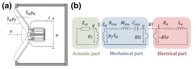
Closed-Box Dynamic Speaker System Schematic Diagram and Circuit Analogy
Readers could be perplexed. This AER appears to have the same definition and structure as the loudspeaker, with the exception of the vest. In truth, their goals and methods of action are diametrically opposed. Resonator is more common in passive acoustic structures, as the name suggests, stressing that the system receives sound waves and excites its own modes. By including a feedback device to actively regulate the resonant mode, AER completes surface acoustic impedance management. Sound absorption and noise reduction are common applications, which can be defined as "similar" to speakers. The author will sort out and introduce the primary forms, basic concepts, structure, and application scenarios of AER in this post, with the hopes of providing beneficial information to readers.
Ⅰ. Electroacoustic Absorbers, EA
Concept and basic structure
AER was first offered as a way to accomplish extensive sound absorption in the low-frequency region. A single AER used for sound absorption is also known as EA for this purpose.
Broadband sound absorption, particularly at low frequencies, is an issue in both scientific inquiry and technical application. Traditional sound-absorbing materials, such as porous and fibrous materials, cannot achieve effective low-frequency sound absorption under the requirements of thin layers due to the causal nature of the acoustic response (that is, there is a summing rule between the absorption spectrum and the thickness of the sample). Furthermore, the absorption bandwidth and absorption efficiency are mutually restricted for passive, linear time-invariant systems based on the "Bode-Fano" criterion. To obtain a broadband impedance-matched sound-absorbing device, some basic assumptions must be abandoned and these inherent limitations must be overcome.
The first thought that comes to mind while considering these three assumptions: passive, linear, and time-invariant is to solve "passive" and break it by introducing an active control mechanism. The first stage in making an active sound absorber is to replace the passive membrane resonator with a speaker diaphragm and connect the speaker end to a certain electrical impedance or control system. This method of creating electroacoustic absorbers not only improves the resonator's absorption performance but also extends the resonator's bandwidth and synthesizes the shunt impedance to further broaden the absorption bandwidth. In the shunt impedance, substituting the speaker terminal's voltage with an external sensor is a good technique to increase control stability. Dynamic broadband sound absorption can be achieved using sensor-based control technology.
A schematic diagram of a closed-box dynamic speaker is shown below. A speaker can be thought of as a resonator with only one degree of freedom. Under the linear assumption, the motion equation and control equation is:
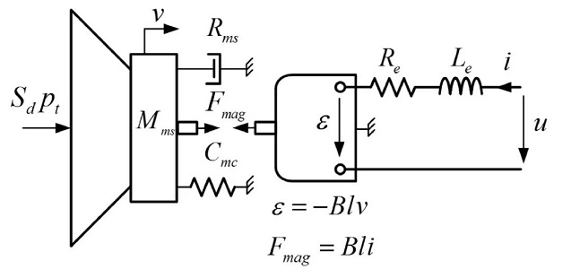

Schematic Diagram of the Closed-Box Dynamic Speaker, AER Prototype
The circuit current is now replaced by the incident sound pressure field as the excitation source. Because the sound field of the application scenario is unknown, a feedback system must be implemented to dynamically change the EA surface's acoustic impedance. Here are two options for providing feedback: The two approaches are shown in the block diagram below: 1. to control the current by detecting the total sound pressure at the diaphragm; 2. to control the current by detecting the speed of the diaphragm.

Moving coil loudspeaker block diagram based on (a) total sound pressure and (b) diaphragm vibration velocity sensor control
The transfer function for the initial sound pressure feedback is the ratio of the circuit current to the total sound pressure:

After introducing the control circuit, the characteristic acoustic impedance of the speaker surface can be represented as:

Then, by altering the transfer function, the speaker's surface acoustic impedance may be dynamically modified to accomplish the desired sound absorption. This technique necessitates a thorough examination of the loudspeaker's mechanical properties, such as the effective piston area and the force coefficient Bl.
The transfer function and characteristic acoustic impedance from the diaphragm velocity V(s) to the circuit current I(s) can also be given for the second form of diaphragm velocity feedback:
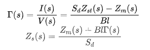
Because pressure sensors are less expensive and easier to use than speed sensors, the first transfer function is frequently preferred over the second. As a result, by replacing the circuit driving part of the speaker with the signal feedback system of the pressure sensor, the mechanical resistance and reactance of the diaphragm can be changed simultaneously to control the dynamic response of the diaphragm to the external sound pressure, resulting in the desired sound absorption effect.
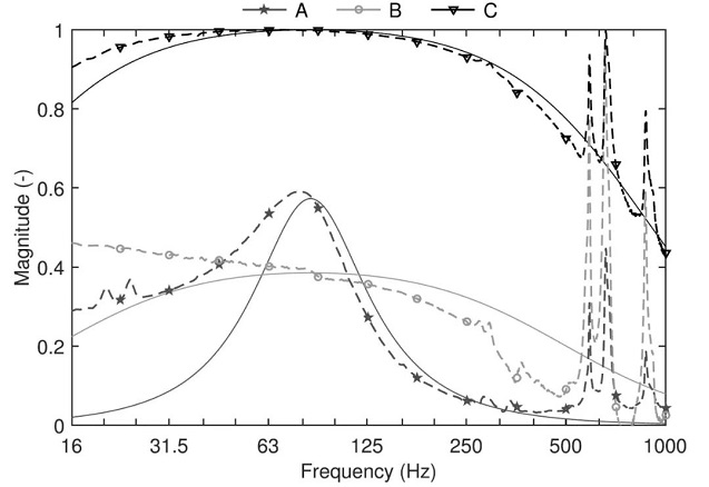
Comparing the EA Sound Absorption Coefficient under the Open Circuit (example A) and the Control (example B and C), the EA Sound Absorption Coefficient under the Control has Obvious Advantages, and the Two Control Effects are Adjustable
Application scenario
The room mode will cause the spatial and frequency distribution of the sound field to be unequal in key listening places, such as recording studios or home theaters, consequently affecting the sound quality, and most unneeded indoor resonances occur in the lowest detectable sound range [20-200Hz]. To balance the indoor response, broadband low-frequency sound absorbers are required to effectively absorb these modes.
Traditional passive porous materials, on the other hand, have a hard time absorbing sound in the low frequency range. The quarter wavelength of the sound wave absorbed is utilized to build the sound-absorbing wedge used in the anechoic chamber. It has a minimum thickness of roughly 3 meters at 30Hz. Although the volume can be lowered by stacking layers, it is not acceptable for most indoor spaces as a decorating medium. Low-frequency sound absorption is also accomplished with passive sound absorbers such as Helmholtz resonators. However, these high-Q resonators will have a restricted effective sound absorption bandwidth and will not be able to meet the low-frequency broadband noise reduction requirements. The emergence of EA at this time allows an exploration program.
EA has demonstrated that it can efficiently equalize the waveguide's multiple modes. To identify the optimal performance of the EA in the room scenario, first study the sound energy distribution of the room with a given geometric shape and define the pressure node (a room with a rectangular parallelepiped structure). To put it another way, the most common pattern is in the corner). Because the center frequencies of different modes differ, the corresponding frequency band mode can be efficiently absorbed by modifying the target surface acoustic impedance of the sound absorber, resulting in the effect of equalizing the indoor mode.

The Mode Sound Pressure Level is Greatly Lowered Under Control When Compared to the 35.3Hz Mode Sound Pressure Level Distribution in the Room where EA is Positioned in the Four Corners.
It's worth noting that, in addition to civilian applications, the efficacy of EA mode control has been demonstrated in the noise reduction of aircraft engine pipelines, demonstrating the system's stability.
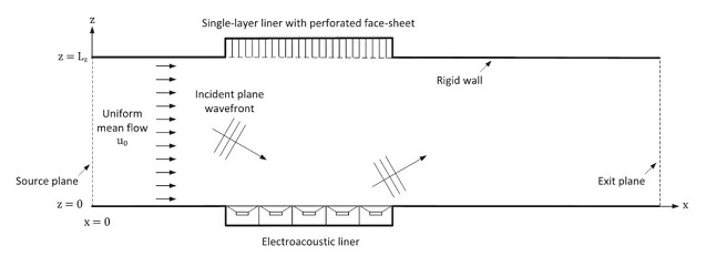

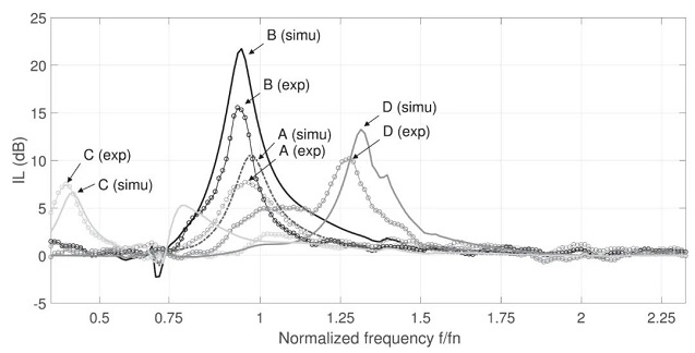
Schematic Diagram of the Work of the EA Array Placed in the Pipeline of the Aircraft Engine, Physical Photos, and Effective Reduction of the Sound Pressure Level
Ⅱ. Active Electroacoustic Resonator (AER)
Concept and basic structure
As previously stated, the AER concept presented EA as an early solution for low-frequency sound absorption. AER is a more complete active electroacoustic resonator that can be used to construct an array, and it expands the field of sound absorption and noise reduction to the field of aberrant reflection sound wave control using the metasurface concept.
Acoustic apparatus that manipulates sound waves has piqued the curiosity of the physics and engineering communities for many years. Metasurface, as a new field in recent years, has a lot of potential in sound field regulation. The metasurface is made up of sub-wavelength superatoms (units) that are arranged in a plane according to a mathematical formula. The transmission/reflection amplitude and phase characteristics of these sub-wavelength atoms may be controlled, giving the metasurface a bizarre local phase shift or unique wave absorption characteristics. It provides a platform for sound wave manipulation, including frequency-selective acoustic metasurfaces, adaptive wavefield shaping, asymmetric energy transmission, simulation calculations, acoustic bi-anisotropy, real-time and broadband acoustic stealth, and holographic realization, among other things.
The reflection coefficient and phase are spread on the metasurface for reflection wave management, and the wavefront manipulation of the reflected sound wave is possible. The advantage of reconfigurable reflection for AER comes from its dynamic surface impedance changeable characteristic. The needed reflection coefficient and phase can be achieved at any location on the metasurface by modifying its surface acoustic impedance, resulting in a beam at a given angle. form.
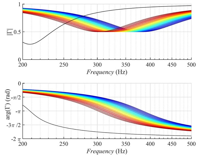
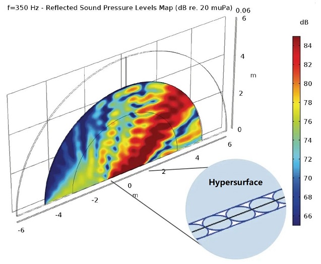
The Reflection Amplitude and Phase of the AER Unit with Different Impedances, the Frequency is 350Hz, and the Specified Angle is 60°, the Reflected Sound Pressure Level of the 32*32 Metasurface Unit Array
AER's structure is depicted in the diagram below. The speaker unit and the sound pressure feedback system stated earlier make up the majority of this construction.
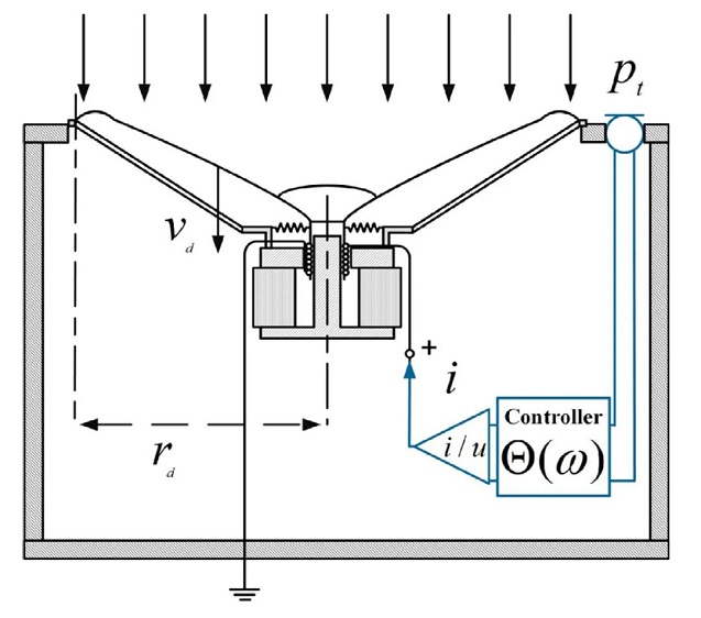
Schematic Diagram of AER Unit
The transfer function of the active system is shown here for the principle of the system, as well as the relationship between the target surface acoustic impedance and the transfer function.
We may deduce the required control transfer function by using the target impedance of the (m, n)th unit on the array as a function of the required beamforming.
The AER system's implementation block diagram, which is similar to EA, is depicted below. Its primary purpose is to provide feedback and control of the target surface's acoustic impedance, and the metasurface reflection beam can be adjusted by meeting the array's spatial phase requirements.

AER System Implementation Block Diagram
Application scenario
AER can achieve a wide range of applications as a metasurface unit with a more thorough theory. It features dynamically adjustable scattering characteristics that modify acoustic resonance because it can be based on the conversion of electrical energy to acoustic waves, acoustic interference, and field programmable gate array (FPGA) technology. It demonstrates a class of acoustic resonance scatterers with externally controlled absorption energy levels and externally tunable resonance bandwidth and frequency. It achieves active feedback control based on the sensed pressure signal by using the electroacoustic resonator's transmutability, and then injects a passband current signal that is correctly connected to the sensed pressure, resulting in acoustic resonance with controllable performance. Acoustic engineers and applied physicists will benefit substantially from AER's present work.It can help build a new generation of dynamic acoustic systems, such as fast switching with novel physical features or time-modulated artificial structures, as well as low-loss acoustic metamaterials with calibrated resilient resonance frequencies and programmable bandwidth active resonators.
Ⅲ. Summary
This article discusses the applications of EA as a sound absorber and AER as a programmable array unit. These programmable acoustic resonators offer a wide range of applications in sound absorption and noise reduction, as well as beam steering. However, there are several drawbacks to using this type of system. A linear transfer function, for example, is used to model the system. A model like this can only approach reality, and when a nonlinear sound source is present, a control system like this will have some errors. However, the AER concept's suggestion opens up new possibilities for sound field manipulation, and we look forward to seeing how this study progresses.
1. What is the difference between an oscillator and a resonator?
Oscillator is the process of converting DC power into AC power to generate AC signals of a certain frequency. A resonator is a circuit that resonates a signal of a certain frequency, and is mainly used to filter out a certain frequency.
2. What is the difference between a resonator and a filter?
The coordination of the resonator can make the part of the signal at the input end equal to the resonant frequency amplified, protruding, and passing through.
The filter is a range pass principle, and there are common high-pass, low-pass, and passband cutoffs. Because of its attenuation problem, it is not used in point pass.
3. What is the role of the resonator?
The resonator is to let a certain (should be called a certain section) frequency signal pass through, block other frequency signals, and achieve the purpose of selection. When the signal frequency is equal to the natural frequency of the resonator, the signal passes smoothly like a small resistor (or Wire) is like a large impedance when a frequency far away from the natural resonant frequency tries to pass through it.
 A Simple Method to Build a Programmable OscillatorUTMEL27 May 20225200
Hello, this is Candy. Nice to meet you. Digital potentiometers (digiPOT) are versatile and can be used for a variety of tasks, including filtering and generating AC signals. However, depending on the application, the frequency must occasionally be able to fluctuate and be altered. Programmable solutions that permit frequency change through the appropriate interface are quite handy and, in some situations, extremely beneficial to the development of such designs. Using digiPOT, this article shows how to make a programmable oscillator in which the oscillation frequency and amplitude may be modified independently of one another.
Read More Introduction to Types of Oscillator CircuitsUTMEL20 February 202114235
The oscillator operates on the theory of the oscillation and it is a mechanical or electronic unit. The periodic difference between the two items is dependent on the variations in the electricity. The oscillations are used in the watches, clocks, metal detectors and in many other applications use the oscillators.
Read More What are Resonators?UTMEL07 January 202615058
A resonator is an electronic component that can generate a resonant frequency. It has the characteristics of stability and good anti-interference performance. Like the low-frequency circuit, the resonator is also the basic component of the radio frequency circuit. It is widely used in filters, oscillators, frequency meters and adjustable In circuits such as amplifiers. The commonly used RF/MW resonators are basically transmission line resonators.
Read More How to Understand the Oscilloscope Bandwidth?UTMEL13 December 20218394
When a user selects an oscilloscope for essential measurements, the oscilloscope's key characteristics are frequently the only criteria used to determine which oscilloscope to employ. An oscilloscope's most essential index parameters are:Bandwidth, Sampling Rate, Record length
Read More Active Electroacoustic Resonator-Silent SpeakerUTMEL10 November 20213783
Hello everyone, I am Rose. Today I will introduce active electroacoustic resonator to you. The only component of this system is a closed-box dynamic speaker. The surface acoustic impedance of the diaphragm is appropriately changed by connecting an active electrical control system to generate an independently tunable sound absorption coefficient, bandwidth, and resonance frequency.
Read More
Subscribe to Utmel !
![XB7EV04GP]() XB7EV04GP
XB7EV04GPSchneider Electric
![Q16F1CXXG24AE]() Q16F1CXXG24AE
Q16F1CXXG24AEAPEM Inc.
![XB5EVG8]() XB5EVG8
XB5EVG8Schneider Electric
![XB6EAV4BP]() XB6EAV4BP
XB6EAV4BPSchneider Electric
![82-5151.0123]() 82-5151.0123
82-5151.0123EAO
![82-5151.0113]() 82-5151.0113
82-5151.0113EAO
![XVLA143]() XVLA143
XVLA143Schneider Electric
![XB7EV07GP3]() XB7EV07GP3
XB7EV07GP3Schneider Electric
![Q8F1CXXB24E]() Q8F1CXXB24E
Q8F1CXXB24EAPEM Inc.
![9001KP]() 9001KP
9001KPSchneider Electric


